

Page 1
TM
Installation
DO N
O
T
D
IS
CA
R
D
Instructions
Models:
ODGO324-IPI-LP
ODGO324-IPI-NG
Outdoor Burner and Log Set
Report # 324-L-15-4
Check with your local building code agency before you begin installation to ensure compliance with local codes, including
the need for permits and follow-up inspections. If you encounter any problems regarding code approvals, or if you need
clarification of any of the instructions contained here, contact the Technical Services Dept., Hearth & Home Technologies
Inc., www.hearthnhome.com.
Installation and service of this
appliance should be performed by
qualified personnel. Hearth & Home
Technologies suggests NFI certified
or factory-trained professionals,
o r t e ch n ic i an s
s u p e r v i s e d b y
an N FI c er ti f ie d
professional.
CAUTION
DO NOT DISCARD THIS MANUAL
•
• Im portan t operating
a n d m a i n t e n a n c e
instructions included.
•
Rea d , understand
an d fo ll ow th es e
instructions for safe
i ns ta ll at io n a n d
operation.
Leave this manual with
party responsible for
use and operation.
WARNING
If the information in these instructions is not followed exactly, a
fire may result causing property
damage, personal injury, or death.
• Do not store or use gasoline or other flammable vapors and liquids in the vicinity of
this or any other appliance.
• What to do if you smell gas:
- Do not try to light any appliance.
- Do not touch any electrical switch. Do not
use any phone in your building.
- Immediately call your gas supplier from
a neighbor’s phone. Follow the gas
supplier’s instructions.
- If you cannot reach your gas supplier, call
the fire department.
• Installation and service must be performed
by a qualified installer, service agency, or
the gas supplier.
Note: An arrow () found in the text signifies change in
content.
Hearth & Home Technologies • Grand Oak Gas Log Sets • 4004-320 2/2011
WARNING
HOT! DO NOT TOUCH.
SEVERE BURNS MAY RESULT.
CLOTHING IGNITION MAY RESULT.
Glass and other surfaces are hot during
operation and cool down.
• Keep children away.
• CAREFULLY SUPERVISE children in same room as
appliance.
• Alert chil d r e n and adults to haza r d s of high
temperatures.
• Do NOT operate with protective barriers removed.
• Keep cl o t h i n g , fu r n i t u r e , dr a p e r i e s and ot h er
combustibles away.
In the Commonwealth of Massachusetts:
• This appliance must be installed by a licensed plumber
or gas fitter.
• The chimney flue damper, when used with gas logs, will
be welded open or completely removed.
• A CO detector shall be installed in the room where the
appliance is installed.
1
Page 2

Read this manual before installing or operating this appliance.
Homeowner Reference Information
Model Name: Date purchased/installed:
Serial Number: Location on appliance:
Dealership purchased from: Dealer phone:
Notes:
We recommend that you record the following pertinent
information about your gas log set:
Please retain this owner’s manual for future reference.
Congratulations
Congratulations on selecting a Hearth & Home Technologies
gas log set—an elegant and clean alternative to burning
wood. The Hearth & Home Technologies gas log set you
have selected is designed to provide the utmost in safety,
and reliability.
As the owner of this new outdoor gas log set, you’ll want to
read and carefully follow all of the instructions contained in
this owner’s manual. Pay special attention to all cautions
and warnings.
This owner’s manual should be retained for future reference.
We suggest you keep it with your other important documents
and product manuals.
The information contained in this owner’s manual, unless
noted otherwise, applies to all models and gas control
systems.
Listing Label Information/Location
The model information regarding your specific gas log set can be found on the rating plate.
Model #
Serial #
Report # 324-L-15-4
2.26
Gas Type
2
Hearth & Home Technologies • Grand Oak Gas Log Sets • 4004-320 2/2011
Page 3
WARNING
WARNING
Improper installation, adjustment, alteration, service
or maintenance can cause injury or property damage.
Refer to the owner’s information manual provided with
this appliance. For assistance or additional information
consult a qualified installer, service agency or the gas
supplier.
CAUTION
Sharp Edges
• Wear protective gloves
and safety glasses during
installation.
A. Design and Installation Considerations
The Gas Log Hearth Kit consists of the following:
• Log Set
• Burner Pan/Grate Assembly
• Lava Rock
• Damper Stop
B. Tools and Supplies Needed
Tools and supplies normally required for installation:
Pliers
Phillips screwdriver
Tape measure
Crescent wrenches
Gas shutoff valve
Non-corrosive leak check solution
3/4 in. wrench, 7/16 in. wrench
C. Important!
• Do not remove any of the attached metal plates, which
contain important safety and operating information.
• Keep the appliance area clear and free of all combustible
materials, gasoline and other flammable vapors and
liquids.
• Any safety screen or guard removed during servicing must
be replaced before operation.
• A qualified service technician must perform installation
and repair. The appliance should be inspected and cleaned
annually by a qualified service technician. More frequent
cleaning may be required due to excessive lint, dust, pet
hair, etc. It is imperative that the control compartments,
burners and air passageways are unobstructed during
operation.
WARNING
HOT! DO NOT TOUCH.
SEVERE BURNS MAY RESULT.
CLOTHING IGNITION MAY RESULT.
Glass and other surfaces are hot during
operation and cool down.
• Keep children away.
• CAREFULLY SUPERVISE children in same room as
appliance.
• Alert chil d r e n and adults to haza r d s of high
temperatures.
• Keep cl o t h i n g , fu r n i t u r e , dr a p e r i e s and ot h er
combustibles away.
- Review proper placement of logs,lava rock.
Check the wiring.
- Ensure there are no gas leaks.
- Ensure the flow of combustion and ventilation air is not
obstructed (front grilles and vent caps).
• Before installing into a solid fuel burning fireplace, the
chimney and firebox should be inspected and cleaned to
remove soot, creosote, ashes, paint, bird nests etc.
• Annual examination of the chimney must be performed
by a qualified agency to ensure proper ventilation of flue
gases created by this appliance.
• Have the chimney and adjacent structure inspected
and cleaned by qualified professionals. Hearth & Home
Technologies recommends that NFI or CSIA certified
professionals, or technicians under the direction of certified
professionals, conduct a minimum of an NFPA 211 Level 2
inspection of the chimney.
• Replace component parts of the chimney and fireplace as
specified by the professionals.
• Ensure all joints are properly engaged and the chimney
is properly secured.
• Do not allow fans to blow directly into the fireplace. Avoid
any drafts that alter burner flame pattern.
• Do not use a blower insert, heat exchanger insert or other
accessories not approved for use with this appliance.
• This appliance must have a screen in place while the
appliance is in operation and, unless other provisions for
combustion air are provided, the screen shall have an
opening for introduction of combustion air.
• Solid fuels shall not be burned in a fireplace where a
decorative appliance is installed.
• If glass doors are present, the glass doors must be fully
opened while appliance is in operation.
Fire Risk
Exhaust Fumes Risk
• Do NOT use this appliance as a “ventfree” heater.
The flue must be permanently open according
to Tables 1 and 2.
Hearth & Home Technologies • Grand Oak Gas Log Sets • 4004-320 2/2011
3
Page 4
WARNING
Do NOT use this appliance if any part has been under
water. Immediately call a qualified service technician
to inspect the appliance and to replace any part of the
control system and any gas control which has been
under water.
D. Appliance Certification
This appliance is design certified by Omni International under the ANSI Z21.60b-2004 or CSA 2.26b-2004, Decora-
tive Appliances for Installation in Solid-fuel Burning
Fireplaces. Installation and the provisions for combustion
and ventilation air must conform to the National Fuel Gas
Code, ANSI Z223.1/NFPA 54, or the CSA B149.1, Natural
Gas and Propane Installation Code.
E. Gas Supply Connection
A 3/8 in. flared fitting has been installed on the gas valve
inlet at the factory. Ensure fittings are of the appropriate size
and type on the gas line connection. If the tubing has to be
cut to length be sure to use the proper cutting and flaring
tool. Also, be careful not to crimp the tubing while bending. If
the tubing becomes crimped, do not use for installation.
Gas resistant pipe compound must be used on all threaded
male connections to ensure a tight seal.
F. Gas Pressure
Proper input pressures are required for optimum appliance
performance. Gas line sizing requirements need to be made
following NFPA51.
WARNING
Fire Risk
Explosion Risk
High pressure will damage valve.
• Disconnect gas supply piping BEFORE
pressure testing gas line at test pressures
above 1/2 psig.
• Close the manual shutoff valve BEFORE
pressure testing gas line at test pressures
equal to or less than 1/2 psig.
WARNING
Fire Risk
Explosion Risk
Verify inlet pressures.
• Hi g h pr e ss ur e ma y cau s e ov e rf ir e
condition.
• Low pressure may cause explosion.
Install regulator upstream of valve if line
pressure is greater than 1/2 psig.
• Gas Supply Pressure: Minimum inlet gas supply pressure
must be 7.0 in. W.C. for natural gas or 11 in. W.C. for LP
gas for the purpose of input adjustment. Maximum inlet
gas pressure must not exceed 10.5 in. W.C. for natural
gas or 13 in. W.C. for LP gas. The gas line supplying the
appliance must be sufficient size to furnish the appropriate
supply pressure to the appliance while operating in the
“High” setting.
• Pressure tap screws must be closed before turning gas
on to the appliance.
• Gas Line Pressure Test: Perform pressure test according
to state and local code (if pressure exceeds 1/2 in. psi (3.5
kPa)) before appliance is connected. Be sure to release
air pressure from the gas line before connection is made
to the appliance. Excessive pressure will damage the gas
control and may cause a gas leak.
• Gas Leak Test: Make sure the gas connections are tight.
Turn on the gas and coat each joint with a non-corrosive
gas leak check solution. Air bubbles will form indicating
any leaks. DO NOT USE A FLAME OR ANY TYPE OF
IGNITION SOURCE TO CHECK FOR LEAKS. All leaks
must be corrected before proceeding with installation.
• The appliance must only be installed in a solid-fuel burning
fireplace with the flue damper clamped open according
to Tables 1 and 2. The fireplace must be constructed of
non-combustible material.
• The minimum permanent free opening (in square inches)
that must be provided by the fireplace chimney or damper
to vent the flue gases is provided in Tables 1 and 2. If the
free opening is smaller than the specified area, do not use
this appliance.
• The damper must be removed or fixed in a manner in
which will secure it open. Some jurisdictions require the
damper to be removed or permanently welded fully open.
Check with state and local codes.
• Be sure that the chimney is completely unobstructed to
ensure proper ventilation of flue gases including carbon
monoxide (CO). CO (a poisonous gas) is tasteless,
odorless, colorless and undetectable without proper
equipment.
• Refer to Table 3 to determine minimum fireplace opening
requirements before proceeding.
WARNING
Asphyxiation Risk
This appliance produces carbon monoxide
(CO).
• The free opening areas (in square inches)
of the chimney damper as shown in the
following tables must be met.
• User must make sure damper is locked
open.
• The installer is responsible to ensure
proper ventilation of flue gases before
appliance is used.
Fire needs to draft properly fo r sa f e
operation.
4
Hearth & Home Technologies • Grand Oak Gas Log Sets • 4004-320 2/2011
Page 5
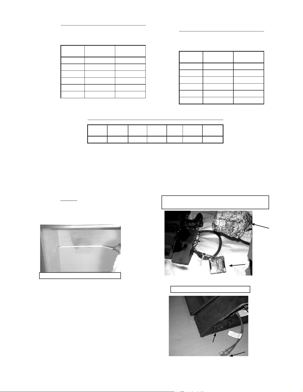
Table 1 for Factory Built Fireplaces
Free Opening Area (in square inches) of
Chimney Damper for Venting combustion
Chimney Ht.
(Feet)*
10 35.3 not approved
15 26.4 38.5
20 22.1 31.2
25 18.1 27.3
30 17.3 24.6
35 15.9 22.1
ODGO 324
LP Gas
ODGO 324
Natural Gas
Table 3 for Minimum Fireplace Dimensions
Table 2 for Masonary Built
Fireplaces
Free Opening Area (in square inches) of
Chimney Damper for Venting combustion
Chimney Ht.
(Feet)*
6 49.2 64
8 45.5 59.7
10 41.7 54.3
15 37.7 48.8
20 34.3 44.4
30 31.2 40.3
ODGO 324
LP Gas
ODGO3 24
Natural Gas
Log Set
ODGO324 34 in. 23 in. 22 in. 22 in. 88,000 80,000
Front
Opening Depth Height
G. Inspect the Appliance and Components
• Remove the contents from the carton labeled “Burner”.
Attached to the burner are tags identifying the manufacturer
name, serial number, model number (including gas log
size), BTU ratings, gas type, etc.
• Review the attached tags before proceeding. Ensure
that all minimum fireplace dimension requirements are
achieved using Table 3 . See Figure 1. Ensure the gas
type provided in the fireplace coincide with the gas type
marked on the tag.
Rear
Width
Natural
BTU
Propane
BTU
• An On/Off switch is provided as part of the assembly. It
is located on the front right side of the burner assembly
as shown in Figure 3A.
• Optional remote control system can be incorporated
with this system by connecting the remote system to the
connection wires shown in Figure 3A.
Figure 3 Battery Box and Cover (for IPI units only)
Battery Box Cover
Battery Box
Figure 1 Measure Firebox
• The burner is assembled with the controls installed at the
factory and is designed to connect one end of the 3/8 in.
supply line before placing inside the fireplace. Ensure the
connection is tightened using a 3/4 in. wrench.
• Place the burner towards the rear and center of the
fireplace and connect to the gas line. Follow instructions
in “F. Gas Pressure” to check for gas leaks.
• IPI models include a battery box which holds 2 “D” size
batterys. The battery box should be placed in the right
front corner of your fireplace and covered with the log
cover as shown in Figure 3.
Hearth & Home Technologies • Grand Oak Gas Log Sets • 4004-320 2/2011
Figure 3A Control Box for IPI
On/Off Switch
Optional Remote
Connection
5
Page 6

H. Lava Rock Installation
• Pour Lava Rock into the burner pans to the point where
the burner pipe is covered. See Figure 5.. Be sure not to
cover pilot assembly.
• Inspect the pilot burner to ensure it is clear of any
lava rock.
• The gas burns at the point of the least resistance. In
case of an uneven flame pattern it may be necessary to
adjust the materials in the pans (using an object such as
a screwdriver) to achieve the desired effect.
• Place desired amount of lava granules on the floor of the
fireplace. (Lava granules may contain moisture which,
when heating, may cause it to pop out during installation
and set-up.) Ensure the controls and switches are
unobstructed after the granules are installed.
Figure 5 Lava
Note: The state of Massachusetts requires that the
chimney flue damper, when used with gas logs, be welded
open or completely removed. In the Commonwealth of
Massachusetts this appliance must be installed by a
licensed plumber or gasfitter.
I. Inspect the Venting System
The fireplace venting system is designed and constructed to
develop a positive flow adequate to remove flue gases to the
outside atmosphere. See fireplace installation instructions.
• The gas burns at the point of the least resistance. In
case of an uneven flame pattern it may be necessary to
adjust the materials in the pans (using an object such as
a screwdriver) to achieve the desired effect.
• Place desired amount of lava granules on the floor of the
fireplace. (Lava granules may contain moisture which,
when heating, may cause it to pop out during installation
and set-up.) Ensure that the controls and switches are
unobstructed after the granules are installed. DO NOT
COVER THE AIR MIXER LOCATED ON THE LOWER
LEFT SIDE OF THE BURNER.
• Place logs as shown in Sections S thru Z.
• Place accent logs around burner on floor of fireplace.
WARNING
Fire Risk
Explosion Risk
Personal Injury Risk
Failure to position the parts in accordance
with the diagrams provided with the log
pa ckages or fail ure to use onl y parts
approved with this appliance may result in
property damage or personal injury.
CAUTION
• Logs can get very hot. Handle only when they are
cool.
J. Damper Stop Installation Instructions
Included in the burner assembly box is a damper stop clamp
which attaches to the damper, if fireplace is constructed
with a damper, as shown (Figure 8). Install the clamp to the
damper ensuring that the minimum requirements (Tables 1
and 2) are achieved. Use a 7/16 in. wrench to secure the
clamp to the damper. If the damper clamp provided does
not fit your application, other means of securing the proper
opening must be provided by the installer.
WARNING
Fire Risk
Explosion Risk
Personal Injury Risk
An explosion could occur if a connection is
made directly to an unregulated propane
(LP) tank.
6
Hearth & Home Technologies • Grand Oak Gas Log Sets • 4004-320 2/2011
Figure 8 Damper Stop Clamp
Page 7

K. Cleaning and Maintenance Instructions
Always remember:
• Do not place an y combust i ble mater ial near th e
appliance.
• Do not place any paper, trash or other material on the log
set or in the fireplace.
• Do not touch any part of the appliance when it is in
operation.
• Do not operate this appliance without the fireplace screen
closed.
Your appliance is designed to be virtually maintenance free,
although periodic visual inspection and cleaning is required.
Follow the instructions below for the correct procedures. An
annual examination and cleaning the venting system by a
qualified person is also recommended.
CAUTION
Before cleaning the appliance, be sure it is turned
completely off. The pilot should also be turned off. The
unit must be completely cooled.
Do not allow soot to build up on the logs
Your logs require little care. Keep the burner assembly, logs
and burner area surrounding the logs clean by brushing with
a dry paint brush at least twice a year.
• Always turn off the gas to the pilot before cleaning.
For relighting, refer to Section P Thru R. Lighting
Instructions.
• Always keep the appliance clean and free from combustible
materials, gasoline and other flammable vapors and
liquids.
• Never obstruct the flow of combustion and ventilation air.
Keep the front of the appliance clear of all obstacles and
materials.
• Leave clearance of at least 36 in. from the front of the
fireplace.
Hearth & Home Technologies • Grand Oak Gas Log Sets • 4004-320 2/2011
7
Page 8

L. Lighting Instructions
• IPI Pilot Valve (IPI)
FOR YOUR SAFETY READY BEFORE LIGHTING
WARNING: If you do not follow these instructions exactly, a fire or explosion may result
causing property damage, personal injury or loss of life.
A. This appliance is equipped with an intermittent Pilot ignition (IPI) device which automatically lights the
burner. DO NOT try to light the burner by hand.
B. BEFORE LIGHTING, smell all around the appliance area for gas. Be sure to smell next to the floor
because some gas is heavier than air and will settle on the floor.
WHAT TO DO IF YOU SMELL GAS
Do not try to light any appliance.
Do not touch any electrical switch: do not use any phone in your building.
Immediately call your gas supplier from a neighbor’s phone. Follow gas supplier’s
instructions.
If you cannot reach your gas supplier, call the fire department.
C. Do not use this appliance if any part has been under water. Immediately call a qualified service
technician to inspect the appliance and replace any part of the control system and any gas control
which has been under water.
WARNING
DO NOT CONNECT 110 VAC TO THE CONTROL VALVE.
-Improper installation, adjustment, alteration, service or maintenance can cause injury or property damage.
-This appliance needs fresh air for safe operation and must be installed so there are provisions for
adequate combustion and ventilation.
-If not installed, operated, and maintained in accordance with the manufacture’s instructions, this product
could expose you to substances in fuel or fuel combustion which are known to the State of California to
cancer, birth defects or other reproductive harm.
-Keep burner and control compartment clean.
CAUTION
Hot while in operation. Do not touch. Keep children, clothing, furniture, gasoline and other liquids having
flammable vapors away.
LIGHTING INSTRUCTIONS IPI
1. Turn off all electric power to the appliance.
2. This appliance is equipped with an ignition device which automatically lights the burner. DO NOT try
to light the burner by hand.
3. Wait (5) minutes to clear out any gas. Then smell for gas, including near the floor. If you smell gas,
STOP! Follow “B” in the Safety Information above. If you do not smell gas, go to the next step.
4. Turn on all electric power to the appliance.
5. To light the burner, flip the ON/OFF switch to the “ON” position (the ON/OFF switch may include a
wall switch, if so equipped).
6. If the appliance will not operate, follow the instructions “To Turn Off Gas to Appliance” and call
your service technician or gas supplier.
TO TURN OFF GAS TO APPLIANCE
1. Turn off all electric power to the appliance if service is to be performed.
2. Flip the ON/OFF switch to the “OFF” position.
Gas Valve
8
Hearth & Home Technologies • Grand Oak Gas Log Sets • 4004-320 2/2011
Page 9

M. Fequently Asked Questions
Can I close the glass doors on my fireplace when using my gas logs?
No. The gas log sets are designed for use in fireplaces with all fireplace doors fully opened. Operating your log set with the doors closed will
cause overheating, premature failure of valve systems, and will void the warranty of your log set.
What sort of maintenance do gas logs require?
Vented gas logs do not require regular maintenance. However, it is a good idea to have valves, pilots and gas connections on your set
periodically inspected by a hearth professional. Although it is not required maintenance, annually refurbishing the ember material and periodic
cleaning of the logs will help maintain your set’s beauty and realism.
Can I burn real wood along with my gas logs?
No. The intense heat of a wood fire will damage your logs, burners, grates and valves, and will void your warranty.
Will gas logs help my chimney that drafts poorly?
No. Improper or poor draft will not be helped by gas logs. Please have your chimney inspected by a hearth professional or chimney sweep in
order to determine how to correct the problem.
Can I close my fireplace damper to get more heat from my vented gas log set?
No. Vented gas logs are designed to be operated with the damper in the fully opened position. This gas log set produces carbon monoxide gas.
The damper must be removed or clamped fully open using the “C” clamp provided with the set.
My gas logs make a whistling noise when I burn them. What causes this?
This behavior is normally caused by using a corrugated flex connector to hook up the gas log set. We recommend the installer use the supplied
aluminum connector rather than the corrugated flexible type.
Can I move or change the position of the logs on my gas log set?
Omni certified log sets should not be altered - log placement must be exactly as indicated in the set’s installation instructions.
Can I install my gas log set myself?
No. We recommend installation be performed by an NFI certified hearth professional, HVAC professional, gas fitter, or plumber experienced
in gas log installation. Most localities require installation of any gas appliance to be performed by a professional. Please check with your local
inspection agency/department.
What are the gas logs made of?
The gas logs are made of a mixture of pre-fired, expanded clay and a special high-temperature cement, with a wire mesh reinforcement. This
combination creates a strong, ceramic material capable of withstanding extreme temperatures, yet also allows molding of the intricate detail
found in these gas log sets.
I have a vented log set, and the logs have black soot on them. Is this normal?
Soot build-up on vented gas logs is a normal part of the combustion process. Natural gas log sets generally produce less soot than liquid propane
log sets. We recommend any soot build up be removed periodically using a product designed for gas log soot removal.
Can I add a remote control to my log set after it has been installed?
You can easily add a remote to the gas log set if it is already equipped with an IPI ignition system.
Is the gas log set approved by a testing agency?
Yes. The ODGO series has been design certified by Omni under the ANSI Z21.60-2004 Decorative Appliances for Installation in Solid Fuel
Burning Fireplaces. The installation and the provisions for combustion and ventilation air must conform to the National Fuel Gas Code, ANSI
Z223.1/NFPA 54. Check with your local inspections department for further information.
Hearth & Home Technologies • Grand Oak Gas Log Sets • 4004-320 2/2011
9
Page 10

N. GO324 Grand Oak Series Logs
• Open the log box and remove the paper packaging and logs.
• Inspect each log for breakage that may have occurred during shipping and handling.
SRV737
SRV709
SRV708
SRV816
SRV808
SRV716
SRV728
SRV724
SRV706
10
SRV707
SRV702
Hearth & Home Technologies • Grand Oak Gas Log Sets • 4004-320 2/2011
Page 11

O. GO324 Grand Oak Series Log Placement Instructions
• Place logs EXACTLY as the following photos depict.
SRV737
SRV708
SRV816
SRV709
SRV728
SRV716
SRV707
SRV808
SRV706
Hearth & Home Technologies • Grand Oak Gas Log Sets • 4004-320 2/2011
SRV724
SRV702
11
Page 12

Replacement Parts
TM
Service Parts
Exploded Parts Diagram Beginning Manufacturing Date: 8/1/2010
ODGO Gas Logs Ending Manufacturing Date: Active
ODGO324
IPI Valve Assembly
ODGO 324
Grand Oak Gas Logs
1
15
13
10
9
4
7
8
6
11
3
2
5
14
12
12
Hearth & Home Technologies • Grand Oak Gas Log Sets • 4004-320 2/2011
Page 13

TM
Service Parts
Service Parts List Beginning Manufacturing Date: 8/1/2010
ODGO Gas Logs Ending Manufacturing Date: Active
Grand Oak Gas Logs
# Description of Part ODGO324 Qty.
1 Burner Pan & Grate Assembly (LP Gas)
1 Burner Pan & Grate Assembly (Natural Gas)
2 Switch
3 *Pilot NG
3 *Pilot LP
4 Control Module
5 Battery Holder
6 Valve NG
6 Valve LP
7 Valve Bracket
8 Control Box
9 Control Box Mount
10 Pilot Bracket
11 Wire Harness
12 Switch Wiring Harness (9”)
13 Battery Cover Log
14 Damper Stop Assy
15 Gas Line Connector
Lava Rock
Installation Instructions
SRVODGOIPI-LP
SRVODGOIPI-NG
01-1070
07-1024
07-1023
593-592
593-594A
593-500
593-501
MT-350-VCSS
MT-350-CBASS
MT-350-CBMSS
MT-350-PBSS
593-590A
16-1616
H-0586A
SRV500-SC
FT-1-24
SRVACC10
4004-320
1
1
1
1
1
1
1
1
1
1
1
1
1
1
1
1
1
1
*Stock to Depot
Hearth & Home Technologies • Grand Oak Gas Log Sets • 4004-320 2/2011
13
Page 14

Warranty
14
Hearth & Home Technologies • Grand Oak Gas Log Sets • 4004-320 2/2011
Page 15

Hearth & Home Technologies • Grand Oak Gas Log Sets • 4004-320 2/2011
15
Page 16

Contact Information
DO NOT
D
IS
CARD
TM
Please contact your Hearth & Home Technologies dealer with any questions or concerns.
For the number of your nearest Hearth & Home Technologies dealer, please call 1-800-927-6841 or 1-888-427-3973.
- NOTES -
16
CAUTION
DO NOT DISCARD THIS MANUAL
•
•
• Im porta nt operating
a n d m a i n t e n a n c e
instructions included.
Hearth & Home Technologies • Grand Oak Gas Log Sets • 4004-320 2/2011
Rea d , understa n d
an d fo ll ow th e se
instructions for safe
i ns ta ll at io n an d
operation.
Leave this manual with
party responsible for
use and operation.
 Loading...