

Page 1
THE GBi25 SERIES
B-VENT GAS FIRED FIREPLACE INSERT ROOM HEATER
INSTALLATION & OPERATING
INSTRUCTIONS
This manual must be used for installation of the GBi25 series B-Vent Gas Fired Fireplace Insert and
retained by the homeowner for operation and maintenance instructions.
WARNING: If the information in this manual
is not followed exactly, a fire or explosion may
result causing property damage, personal injury or loss of life.
Do not store or use gasoline or other flammable
vapors and liquids in the vicinity of this or any
other appliance.
What to do if you smell gas
Do not try to light any appliance.
Do not touch any electrical switch; do not use
any phone in your building.
Immediately call your gas supplier from a
neighbors phone. Follow the gas suppliers
instructions.
If you cannot reach your gas supplier, call the
fire department.
Installation and service must be performed by a
qualified installer, service agency or the gas
supplier.
WARNING!
Improper installation, adjustment, alteration, service or maintenance can cause injury or property damage. Refer to this
manual. For assistance or additional information, consult a qualified installer, service agency or the gas supplier.
02-02 1 26678 Rev H
Page 2
GBI25 SERIES B-VENT GAS FIRED FIREPLACE INSERT
Content s
A. Listings and Code Aprovals ..................................................................................................... 3
B. Description of the System .......................................................................................................3
C. System components ...............................................................................................................4
D. Dimensions and Clearances ................................................................................................... 4
E. Pre-Installation Preparation ..................................................................................................... 5
F. Step-by-Step Installation of the System ................................................................................... 6
G. Operating Instructions ...........................................................................................................14
H. Maintenance Instructions....................................................................................................... 16
I. Troubleshooting .....................................................................................................................17
J. Replacement Parts ............................................................................................................... 18
K. Optional Components ...........................................................................................................19
Index ...................................................................................................................................... 23
Warranty ................................................................................................................................ 24
CAUTION:
Do not expose the appliance to the elements (such as rain, etc.)
SAFETY PRECAUTIONS
1. Please read these installation instructions completely
before beginning installation procedures. Failure to
follow them could cause a malfunction resulting in
serious injury and/or property damage.
2. Installation and repair should be done by a qualified
service person. This appliance should also be
inspected annually by a qualified service person. More
frequent inspections/cleaning may be required due
to excessive lint from carpeting, bedding material, etc.
It is imperative that the control compartment and
burners of the appliance be kept clean.
3. The GBi25is a vented gas appliance. Do not burn
wood or other material in this appliance.
4. NEVER leave children unattended when there is a
fire burning in the fireplace.
5. This appliance must be vented with a minimum 4 B-
Vent system and must terminate above the roof line.
Venting must not be connected to a chimney flue
servicing a solid fuel burning appliance.
6. Use only the fuel gas specified on the rating label of
this gas appliance.
7. The appliance area shall be kept clear and free from
combustible materials, gasoline and other flammable
vapors and liquids.
8. While servicing this appliance, always shut off all
electricity and gas to the appliance. This will prevent
possible electrical shock or burns. Also, make sure
the fireplace is completely cooled before servicing.
9. Do not use this appliance if any part has been under
water. Immediately call a qualified service technician
to inspect the appliance and to replace any part of the
control system and any gas control which has been
under water.
10. Be sure to provide adequate clearances around the
air openings into the combustion chamber and
adequate accessibility clearances for servicing and
proper operation.
11. Provisions shall be made to provide adequate
combustion and ventilation air. The flow of combustion
and ventilation air should not be obstructed.
26678 Rev H 2 02-02
Page 3

GBI25 SERIES B-VENT GAS FIRED FIREPLACE INSERT
A. LISTINGS AND CODE APROVALS
U.S. AND CANADA CERTIFICATION
This appliance has been tested in accordance with ANSI
Z21.11.1-1991, CAN/CGA 1-2.1-MB6 and applicable
sections of ANSI Z21.50-1996 CAN/CGA 2.22-M96 and
has been LISTED by Underwriters Laboratories Inc. for
installation and operation as described in these
Installation and Operating Instructions. All components
are UL. AGA, CGA or CSA safety certified.
LOCAL CODES
Check with your local building code agency prior to
installing this appliance to ensure compliance with local
codes, including the need for permits and follow-up
inspections. This installation must conform with local
codes or, in the absence of local codes, with the National
Fuel Gas Code, ANSI Z223.1-latest edition in the U.S.A.
and the CANI-B149-latest edition in Canada. The
appliance, when installed, must be electrically grounded
in accordance with local codes; in the absence of local
codes, with the current National Electric Code ANSI/FNPA
No. 70 (in the U.S.A.) or with the current CSA C2.1 Canadian
Electric Code in Canada.
FUEL
Any additions, changes or conversions required in order
for the appliance to satisfactorily meet the application
needs, must be made by a qualified service technician
using factory specified and approved parts.
If you require assistance during installation, please contact
your local dealer or the Heatilator Technical Services
Department, Hearth Technologies Inc., 1915 W. Saunders
Street, Mt. Pleasant, Iowa 52641 (1-800-843-2848).
HEATILATOR® is a registered trademark of Hearth
Technologies Inc. (HTI), a division of HON INDUSTRIES.
B. DESCRIPTION OF THE SYSTEM
The GBi25 Series is a B-vent gas-fired room heater.
Combustion air is supplied from inside the house.
This HEATILATOR system must consist of the following:
1. Appliance
2. B-Vent Venting System
3. Termination
4. Surround
Tools and building supplies normally required for
installation:
Saw Wall-finishing materials
Pliers Framing material
Hammer Surround
Phillips screwdriver Caulking material
Tape measure Safety gloves
Plumb line Electric drill/bits
Level Framing Square
HIGH TEMPERATURE SEALANT MATERIAL
Sealants that will withstand high temperatures: General
Electric RTV103 (Black), or equivalent. Rutland, Inc.
Fireplace Mortar #63 or equivalent; Dow Corning 732 or
equivalent.
We strongly recommend that you DO NOT install B-Vent
Gas Appliances in strong negative air locations, such
as a basement or a public facility. Living rooms with
cathedral ceilings could be susceptible to a negative
air situation, but such installations can be overcome
through raising the termination, depending on specific
installations. This fireplace uses room air for normal
operation and could have problems establishing a
positive draft in negative air locations. In lieu, we
recommend a direct vent appliance.
Note: Illustrations throughout these instructions reflect
typical installations and are for design purposes only.
Actual installation may vary slightly due to individual
design preferences. However, minimum and maximum
clearances must be maintained at all times.
The illustrations and diagrams used throughout these
installation instructions are not drawn to scale.
02-02 3 26678 Rev H
Page 4
GBI25 SERIES B-VENT GAS FIRED FIREPLACE INSERT
C. SYSTEM COMPONENTS
The table below is a list of only those components which may be safely used with this gas-fired fireplace insert.
rebmuNgolataCnoitpircseD
52iBGtoliPgnidnatS,saGlarutaN-tresnIderiF-saGtneV-B
L52iBGtoliPgnidnatS,saGenaporP-tresnIderiF-saGtneV-B
42DSGmirThtiW)W"2/1-04xH"42(dnuorruSllamS
04DSGmirThtiW)W"2/1-04xH"2/1-82(dnuorruSmuideM
64DSGmirThtiW)W"64xH"33(dnuorruSegraL
PVKCsaGenaporPottiKnoisrevnoC
NVKCsaGlarutaNottiKnoisrevnoC
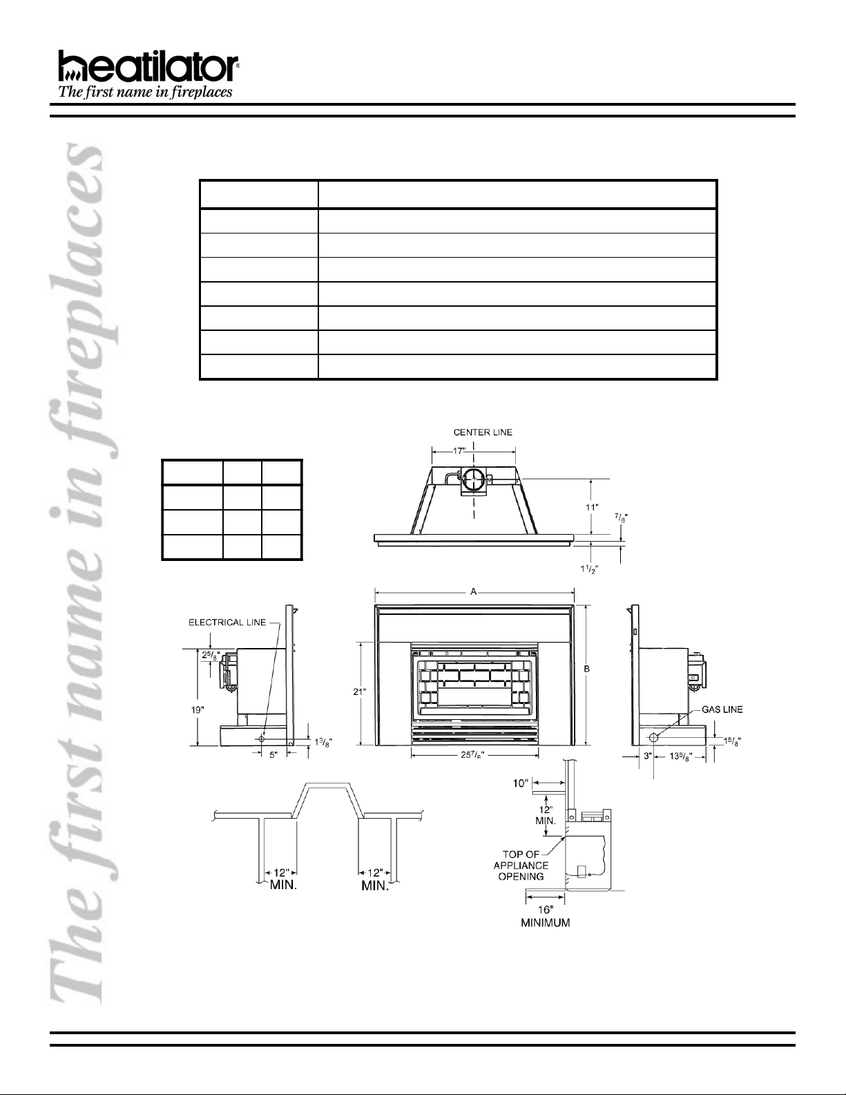
D. DIMENSIONS AND CLEARANCES
LEDOMAB
42DSG"5.04"42
04DSG"5.04"5.82
64DSG"64"33
MANTEL
A combustible mantel may be positioned no lower than 12 above the top of the appliance opening of the existing
fireplace. The combustible mantel may have a maximum depth of 10. Combustible trim materials, such as a surround
or mantel support brackets, protruding no more than 1-1/2 from the face of the existing fireplace, can be placed no
closer than 6 from any edge of the surround.
26678 Rev H 4 02-02
Page 5

GBI25 SERIES B-VENT GAS FIRED FIREPLACE INSERT
E. PRE-INSTALLATION PREPARATION
Installation and repair should be done by a qualified service technician. The appliance should be inspected before
use and at least annually by a qualified service technician. More frequent cleaning may be required due to excessive
lint from carpeting, bedding material, etc. It is imperative that control compartments, burners and circulating air
passageways of the appliance be kept clean.
Due to high temperatures, the appliance should be located out of traffic and away from furniture and draperies.
WARNING!
This appliance may use the B-vent chimney system only and must not be connected to a chimney flue servicing
a separate solid fuel buring appliance.
This appliance must be installed on a noncombustible, flat, solid, continuous surface (i.e. fireplace hearth.)
WARNING!
To prevent contact with sagging or loose insulation, the appliance must not be installed against vapor barriers
or exposed insulation.
1. GAS PRESSURE
For natural gas, the minimum inlet gas supply
pressure is 4.5 inches water column (w.c.), and the
maximum inlet gas supply pressure is 7.0 inches
w.c. Input rate is 17,000 to 22,000 Btu/hr. For propane
gas, the minimum inlet gas supply pressure is 11.0
inches w.c. and a maximum 14.0 inches w.c. Input
rate is 15,000 to 22,000 Btu/hr.
Manifold pressure for this appliance is 1.7 - 3.5 inches
w.c. for natural gas and 5.4 - 11.0 inches w.c. for
propane gas. This appliance has a variable adjust
manifold.
Input (line) and output (manifold) pressure taps are
located at the front of the gas control valve near the
variable regulator for test gauge connection with a
3/8 diameter hose.
A 1/8 NPT plugged tapping is provided on the gas
control valve, near the outlet to the main burner
immediately upstream of the gas supply connection
to the appliance, accessible for a test gauge
connection.
2. HIGH ALTITUDE INSTALLATION
U.S. Installation: Appliances are tested and approved
for elevations from 0-2000 feet (0-610m).
When installing this appliance at an elevation above
2000 feet, it may be necessary to decrease the input
rating by changing the existing burner orifice to a
smaller size. Input should be reduced 4% for each
1000 feet above sea level. Check with the local gas
utility for proper orifice size identification and to see if
the gas in your area has been deregulated. This
appliance is shipped with a .093 in./2.36 mm. orifice
size on natural gas versions and a .056 in./1.42 mm.
orifice size on propane gas versions.
Canadian Installation: Appliances are certified for
elevations from 0-4500 feet. When installing this
appliance at an elevation between 0-4500 feet in
Canada, the input rating does not need to be reduced.
When installing this appliance at an elevation above
4500 feet in Canada, check with local authorities.
Consult your local gas company for assistance in
determining the proper orifice for your location or refer
to ANSI Z23.1-latest edition, Appendix F.
3. COMPONENTS
Before installing this appliance, it may be necessary
to remove the smoke shield, ash lip, refractory,
damper blade, etc. If removed, the label referenced
on page 7 MUST be affixed to the existing fireplace
prior to installation.
02-02 5 26678 Rev H
Page 6
GBI25 SERIES B-VENT GAS FIRED FIREPLACE INSERT
F. STEP-BY-STEP INSTALLATION OF THE SYSTEM
WARNING!
Before starting, do the following:
1. Wear gloves and safety glasses for protection.
2. Keep hand tools in good contition. Sharpen cutting edges and make sure tool handles are secure.
3. Always maintain the minimum air space required to the enclosure to prevent fire.
WARNING!
This appliance is equipped with a safety control system designed to protect against improper venting of combustion products. Operation of this appliance when not connected to a properly installed and maintained venting
system, or tampering with a vent safety shut-off system can result in carbon monoxide (CO) poisoning and
possible death.
1. VENTING REQUIREMENTS
A flue liner from the outlet of the draft hood to the roof
termination is required. This appliance is required to
be connected to a listed 4 diameter, stainless steel
or aluminum flexible gas vent liner with a top
termination. A 4 B-Vent or listed 4 rigid single wall
gas vent may also be used.
Before attempting to run your flue liner, you must make
sure that it will pass through the existing damper area;
this is best done with a flexible liner. In a zero clearance
(factory built) fireplace, the existing damper must be
removed or locked out of the way in the open position.
For masonry fireplaces, if the damper will not allow
the passage or a 4 flex, do not proceed without
consulting a local mason on how to remove or alter
the damper without risk of structural damage or
leakage.
A minimum vertical venting height of 9 feet above the
base of the appliance must be maintined. The
horizontal run must not exceed 50% of the vertical
height. Maximum vertical venting height is 40 above
the base of the appliance. The vent termination must
be in accordance with its respective listing and
manufacturers instructions.
Install 4 flue liner down through the chimney. When
using flexible liner, use caution around the offsets so
as not to rupture the liner. Measure up 16 from the
existing fireplace bottom and leave hanging in
fireplace.
brought into the fireplace through the gas knockouts
provided.
Note: The appliance and its manual shutoff valve must
be disconnected from the gas supply piping system
during any pressure testing of that system at test pressures in excess of 1/2 psi (3.5 kPa). The appliance must
be isolated from the gas supply piping system by closing the manual shutoff valve during any pressure testing of the gas supply piping system at test pressures
equal to or less than 1/2 psi (3.5 kPa).
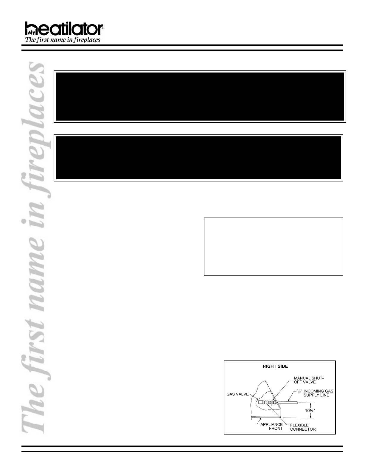
It is recommended that 1/2 inside diameter black
pipe be run into the fireplace through the right side. If
the existing fireplace already has gas run to it, but
through the left side, it is recommended that the gas
be rerouted to the right side. See Figure 1.
Place an elbow at the end of the black pipe so that it
runs perpendicular to the face. A 1/3 flare adapter
(not supplied) is necessary to connect the flex line
(supplied) to the black pipe.
Check for leaks using a soap and water solution or a
leak detector.
2. GAS LINE INSTALLATION
A gas line must run into the existing woodburning
fireplace, for either a factory built or masonry fireplace.
If it is a factory built fireplace, the gas line should be
Figure 1 - Gas Line Installation
26678 Rev H 6 02-02
Page 7
GBI25 SERIES B-VENT GAS FIRED FIREPLACE INSERT
Seal with high temperature silicone at the point where
the gas line enters the existing fireplace to prevent
cold air infiltration.
This fireplace has been altered to
accommodate an insert and should be
inspected by a qualified service technician
prior to re-use as a conventional fireplace.
Label
Note: The above label, located in the instruction
package, must be affixed to the existing fireplace prior
to installation of the GBi25 Gas Fired Fireplace Insert.
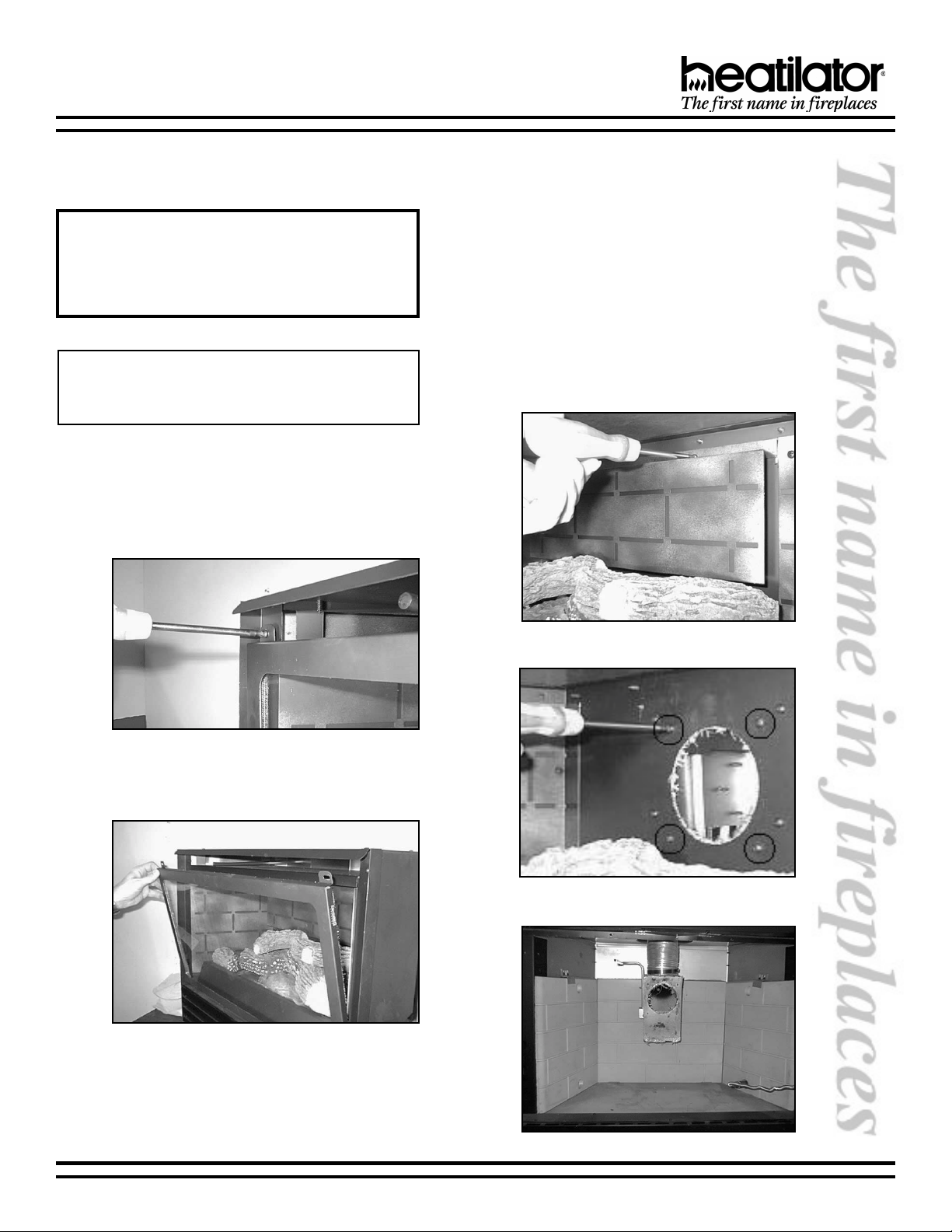
3. APPLIANCE INSTALLATION
a. Firebox Entry
To gain access to the draft hood, remove the two
screws located in the upper corners of the glass
frame. See Figure 2.
the four screws located around the exhaust
opening. See Figure 5. Slide the draft hood out of
the appliance and attach draft hood to flex liner in
appliance with a minimum of three sheet metal
screws. A 4 diameter hose clamp may also be
used. See Figure 6.
The draft hood must be installed so as to be in
the same atmospheric pressure zone as the
combustion air inlet to the appliance and shall
be located so that the relief opening is accessible
for checking vent operation.
Pack the area at the damper with noncombustible
insulation to prevent cold air infiltration into the
fireplace cavity.
Figure 2 - Firebox Entry
Rotate glass frame forward and lift out. See
Figure3.
Figure 3 - Glass Frame Removal
Handle the glass frame with care to avoid striking
or scratching it on hard objects or slamming it
shut.
Remove the two screws on the baffle, as shown
in Figure 4. To remove the draft hood, unscrew
Figure 4 - Baffle Removal
Figure 5 - Draft Hood Removal
Figure 6 - Draft Hood Attachment
02-02 7 26678 Rev H
Page 8

GBI25 SERIES B-VENT GAS FIRED FIREPLACE INSERT
b. Installation of Appliance
1) The appliance should be set on a level
surface. Located on the bottom pan of the
appliance are two 5/16-18 nuts. Bolts
(provided) may be used for leveling purposes.
2) Place appliance on hearth and slide the
appliance into the fireplace. Position the draft
tube in the hold located on the back. Reach
through the exhaust hole and grab the draft
hood. See Figure 7. Continue to slide
appliance back until draft hood is in position.
Reinstall four screws around the exhaust
hole.
GSD24, the bend tab is located on the top of
the right surround side. For Models GSD40
and GSD46 the bend tab is located on the
right side of the top surround. Use a pair of
pliers to bend the tab forward. See Figure 8.
Figure 9 - Installation of Surround Hood
Figure 7
3) Place the flex line through the gas line access
hole on the right side and connect it to the
manual shutoff valve. Turn on the gas and
check for leaks with a soap and water
solution or a gas leak detector. If a leak is
detected, tighten the fitting and recheck all
joints.
Reinstall the baffle with two screws.
c. Surround Installation
1) Carefully remove the surround parts from the
shipping carton. Attach the surround top to
each side with two screws provided. See
Figure 8. Located on the surrounds is a bend
tab used to cover the switch leads. For Model
Figure 8 - Attach Surround Top
Figure 10 - Installation of Surround Hood
2) For zero clearance fireplaces or fireplaces
with combustible material within 12 inches
of the firebox opening, it is required to use
the surround hood (black). This hood is not
required for masonry fireplaces. To install
the surround hood, bend the tabs down, as
shown in Figure 9. Place the tab through the
slots in the surround top and bend the small
tab over. See Figure 10.
3) Place three screws in the surround top and
slide the brass hood over the screws.
Remove the plastic coating on brass before
securing. See Figure 11.
4) Assemble the brass trim with brackets
provided, as shown in Figure 12. Slide the
brass trim on the surround (Figure 13).
5) To install the surround, place hooks on the
surround side into slots located on the
column (Figure 14).
6) Locate the electrical cord on the left side of
the appliance and route it through the
surround and trim. Make sure that the
electircal cord is routed away from the
appliance.
26678 Rev H 8 02-02
Page 9

GBI25 SERIES B-VENT GAS FIRED FIREPLACE INSERT
WARNING!
ELECTRICAL GROUNDING INSTRUCTIONS
This appliance is equipped with a three-prong
(grounding) plug for your protection against shock
hazard and should be plugged directly into a properly grounded three-prong receptacle. Do not cut or
remove the grounding prong from this plug.
Figure 14 - Installation of Surround Hood
7) DO NOT PACK INSULATION INSIDE THE
SURROUND.
8) Remove the switch from wire assembly and
feed wire through the brass trim. See
Figure15. Re-install the switch to the wires
and push into place. See Figure 16.
Important: Remove all shipping material, fingerprints
and smudges from the brass trim prior to burning the
appliance. If this is not done, they will be burned into
Figure 11 - Installation of Hood
the trim.
Figure 12 - Assemble Brass Trim
Figure 13 - Installation of Surround Hood
02-02 9 26678 Rev H
Figure 15 - Installation of ON/OFF Switch
Figure 16 - ON/OFF Switch in Surround Installed
Page 10

GBI25 SERIES B-VENT GAS FIRED FIREPLACE INSERT
d. Rock Wool Placement
The log set is shipped in place. Tear the rock
wool into pieces no larger than 1/2 diameter.
Place the rock wool in front of the flange located
in the middle of the burner. Do not place the rock
wool behind or above the 3/8 flange. This will
block the air slot and cause carbon desposits on
the log. Place the rock wool on both the left and
right sides to complete the burning ember look. It
is not necessary to use the entire bag. See
Figure17.
Figure 17 - Rock Wool Placement
f. Brass Trim Cleaning
All prints and smudges must be wiped clean from
the brass trim prior to initial burn. If this is not
done, these prints will be cured into the brass
finish and set for the life of the appliance. To keep
the finish looking its best, gently wipe with a soft
cloth after the appliance has had ample time to
cool down. If desired, use a non-abrasive cleaner
such as soap and water. Never use any solvent,
thinner or abrasive cleaner since these will
damage the finish.
g. Valve Access
The valve is located behind the control access
panel. Lift the panel up and rotate forward. See
Figure18. This will expose the gas valve, variable
regulator and fan control, as shown in Figure 19.
Note: Placement of the rock wool should be done
with care and time, as this will create the look of
the fire when burning.
e. Glass Frame Installation
1) When cleaning the glass, use only non-
caustic, non-abrasive cleaners. DO NOT
ATTEMPT TO CLEAN HOT GLASS. It is
dangerous, and the glass is more likely to
be stained by the cleaning agent. Stubborn
film can often be removed using Brasso® or
a non-abrasive cleaner.
2) After cleaning the glass, position the tabs on
the glass frame into the slots on the column
of the appliance. Hold door in place and
secure with screws removed earlier. Be
careful not to over-tighten.
WARNING!
Never operate this appliance with the glass removed
or not sealed.
Figure 18 - Valve Access
Figure 19 - Gas Valve, Variable Regulator & Fan Control
WARNING!
Do not operate appliance with the panel(s) removed,
cracked or broken. Replacement of the panel(s)
should be done by a licensed or qualified service
person.
26678 Rev H 10 02-02
Page 11

GBI25 SERIES B-VENT GAS FIRED FIREPLACE INSERT
h. Firebox Bottom Removal
1) Shut off the gas to the appliance before
removing. Remove the glass frame following
instructions found in Step 3a. on page 7.
2) Remove the two screws on the log assembly
(Figure 20). Pull out the log assembly (Figure
21) and place in a safe area. Remove the
four screws located around the firebox
bottom. See Figure 22.
3) To re-install the firebox bottom, reverse the
above steps.
Figure 22 - Firebox Bottom Removal
i. Fan Access
1) Disconnect the power cord or turn off the
circuit breaker before removing the fan.
Remove the firebox bottom following
directions in Step 3h.
2) Remove the four screws located on the fan
bracket (Figure 23). Remove two on the fan
control. Remove the bushing and unplug the
cord from the junction box. Slide the fan
bracket out.
Figure 20 - Log Assembly Removal
3) To re-install fan, reverse the above steps.
Figure 21 - Log Assembly Removal
Figure 23 - Fan Removal
WARNING!
Any safety screen or guard removed for servicing an appliance must be replaced prior to operating this appliance.
Clothing or other flammable material should not be placed on or near the appliance.
02-02 11 26678 Rev H
Page 12

GBI25 SERIES B-VENT GAS FIRED FIREPLACE INSERT
4. WIRING
a. A 110V AC outlet should be located close to the
lower left side of the appliance to allow the fan to
be plugged in. See Figure 24.
Note: This appliance must be electrically wired and
grounded in accordance with local codes or, in the absence of local codes, with National Electric Code ANSI/
NFPA 70-latest edition. This appliance can be used with
a thermostat.
Note: This appliance REQUIRES a 110V AC
supply for operation of the fan.
CAUTION:
Label all wires prior to disconnection when servicing controls. Wiring errors can cause improper and dangerous operation. Verify proper operation after servicing.
Figure 24 - Wiring Diagram
WARNING!
Do not use this appliance if any part has been under water. Immediately call a qualified
service technician to inspect the appliance and to replace any part of the control system and any gas control which has been under water.
26678 Rev H 12 02-02
Page 13

GBI25 SERIES B-VENT GAS FIRED FIREPLACE INSERT
b. Optional Wall Thermostat
The use of a millivolt thermostat is allowed. It
must be located within 20 feet of the appliance.
Figure 25 shows how to connect the thermostat.
Remove ON/OFF switch wires from valve. Place
thermostat wires to the posts marked TH and
TH/TP.
Note: The ON/OFF switch now becomes inoperable.
Figure 25 - Wiring Diagram
5. PRE-USE CHECKLIST
Use the following checklist as a guide to be sure your
installation is correct and complete
Operating instructions have been read and
understood.
All safety warnings have been read and followed.
Note: The fan will not turn on until the appliance has
reached its proper operating temperature. This is
determined by a thermal disc in the fan assembly. Also,
the fan will continue to run until the appliance has cooled
sufficiently after shutdown.
Flex liners and termination cap are properly
installed
Logs and rock wool have been placed correctly.
All fittings are tight and there are no gas leaks.
Glass is in proper position and sealed.
Keep the area near the appliance clear and free from
combustible materials, gasoline and other flammable vapors and liquids.
WARNING!
Prints and smudges are wiped from brass trim.
Check air shutter adjustment.
02-02 13 26678 Rev H
Page 14

GBI25 SERIES B-VENT GAS FIRED FIREPLACE INSERT
G. OPERATING INSTRUCTIONS
FOR YOUR SAFETY READ BEFORE LIGHTING
1. This gas appliance has a manual ignition device that
lights the pilot. When lighting the pilot, follow these
instructions exactly.
2. STOP! BEFORE READING FURTHER, smell around
the appliance area for gas. Be sure to smell next to
the floor because some gas is heavier than air and
will settle to the floor.
3. WHAT TO DO IF YOU SMELL GAS:
Do not try to light the appliance.
Do not touch any electrical switch; do not use any
telephone in your building.
Immediately call your gas supplier from a
neighbors telephone. Follow the instructions of
your utility.
LIGHTING INSTRUCTIONS
If you cannot reach your utility, call the fire
department.
4. If the pilot light and burner went out during use, you
must take the glass off the appliance and wait to clear
out any gas. Follow the lighting instructions below.
5. Use only your hand to push in or turn the gas control
knob to light the pilot. Never use tools. If the knob will
not push in or turn by hand, do not try to repair it; call a
qualified service technician. Using a tool or attempting
repairs may result in a fire or explosion.
6. Do not use this appliance if any part has been under
water. Immediately call a qualified service technician
to inspect the appliance and to replace any part of the
control system and any gas control that has been
under water.
1. STOP! Read the safety information above.
2. Turn off all electric power to the appliance. If your
appliance has a thermostat, set to lowest setting.
3. Open control access panel.
4. Find the pilot. The pilot is inside the combustion
chamber next to the main burner.
5. If the gas control knob is at the OFF position, go to
step 7. If the gas control knob is at the ON position,
go to step 6.
6. If the pilot light went out during normal use with the
gas control knob at the ON position, turn the gas
control knob to the OFF position. REMOVE THE
FIXED GLASS PANEL. Wait ten minutes to clear out
any gas.
7. Smell for gas, including near the floor. If you dont
smell gas, go to the next step. If you smell gas, wait
another five minutes or until the gas odor is no longer
present before continuing. If the odor of gas does not
disappear after fifteen minutes, STOP! Follow B in
the safety information above.
8. Replace glass panel if it has been removed.
9. Turn gas control knob counterclockwise to the PILOT
position.
10. Push the gas control knob in all the way and hold. At
the same time, push in the red ignition button
repeatedly until the pilot lights. Never hold the gas
control knob in for more than ten seconds if the pilot
does not light. Once the pilot lights, continue to hold
the gas control knob in for 15 seconds. Release the
gas control knob and it will pop back up. If pilot does
not remain lit, repeat steps 6 through 9.
If gas control knob does not pop back up when
released, turn the knob to OFF and call your service
technician or gas supplier.
If the pilot will not stay on after two attempts, turn the
gas control knob to OFF and call your service
technician or gas supplier.
11. Turn gas control knob couterclockwise to the ON
position. The knob can be turned to the ON position
only if it is popped out.
12. Close the access panel.
13. Turn on electrical power to the appliance. If equipped
with a thermostat, set to the desired setting.
TO TURN OFF GAS TO APPLIANCE
1. Turn rocker switch to OFF or the wall thermostat to
lowest setting if your appliance is so equipped.
2. Turn off all electric power to the appliance if service is
to be performed.
26678 Rev H 14 02-02
3. Open control access panel.
4. Turn gas control clockwise to OFF.
5. Close control access panel.
Page 15

GBI25 SERIES B-VENT GAS FIRED FIREPLACE INSERT
1. OPERATION PROCEDURE DURING
REGULAR USE
Turn the switch/thermostat to the ON position. This
will ignite the main burner.
2. SHUTDOWN DURING REGULAR USE
Simply turn the switch/thermotat to OFF. This will
disengage the burner and the flames will extinguish.
3. SEASONAL SHUTDOWN
When the burning season comes to an end, the entire
system should be shut down to prevent gas running
to the appliance while it is not in use.
4. FAN OPERATION
The fan control is located behind the control access
panel. Lift the panel up and rotate forward. Locate the
fan control knob and turn. See Figure 18. Close the
control access panel.
5. CHECKING FLAME PATTERNS
Check the flame pattern of the burner periodically,
making sure the flames are steady, not lifting or
floating. The flame color should be blue with yellow
tips. The thermopile tip should be covered with flame.
See Figures 26 and 27.
If the vent configuration is installed incorrectly, the vent
may cause the flames inside the appliance to lift or
ghost - a dangerous situation. Inspect the flames
after installation to ensure proper performance. If the
vent configuration is correct, yet the flames are lifting
or ghosting, shut off gas to the appliance and contact
the dealer for information on remedying the problem.
Figure 26 - Standing Pilot
Note: If the air shutter is open all the way and the flames
remain sooty, shut off gas to the appliance and contact
a qualified service technician.
WARNING!
Children and adults should be alerted to the hazards
of high surface temperatures and should stay away
to avoid burns or clothing ignition. Young children
should be carefully supervised when they are in the
same room as the appliance.
Figure 27 - Flame Patterns
02-02 15 26678 Rev H
Page 16

GBI25 SERIES B-VENT GAS FIRED FIREPLACE INSERT
H. MAINTENANCE INSTRUCTIONS
1. CLEANING THE BURNER AND
CONTROL COMPARTMENT
Keep the burner and control compartment clean by
using a clean, dry paint brush and vacuum at least
once a year. Always turn off the gas valve and the
switch before cleaning. (See Step 1 on the bottom of
page 14.)
2. VENTING SYSTEM INSPECTION
The appliance and venting system should be
inspected before use each season, and at least
annually, by a qualified service person to ensure that
the flow of combustion and ventilation air is not
obstructed.
3. CLEANING THE GLASS
a. It is recommended to wear gloves while handling
or removing the glass. DO NOT REMOVE THE
GLASS WHEN HOT.
b. To remove the glass frame for cleaning, follow
Step 3a. on page 7.
c. To clean the glass, use a nonabrasive, mild
cleaning solution. (For example, a glass cleaner
or an oven cleaner for stubborn film.) Apply an
adequate amount to the glass and wipe off with a
damp cloth. Be sure all cleaner is thoroughly
rinsed from the glass.
d. Never operate this appliance without the glass
properly secured in place or if the glass is broken.
e. In the event of glass breakage, follow glass
removal instructions. This will allow the removal
of all glass fragments and sheet metal edge
protection strips. Vacuum all remaining glass
pieces with a shop vac. DO NOT VACUUM IF
PIECES ARE HOT! Replace glass only with the
correct HTI part ordered direct or through your
local distributor. Never use substitute material.
Only ceramic glass may be used on this
appliance.
5. CHECKING THE VENT SYSTEM
a. The venting system should be tested periodically
to ensure proper operation. This can be done
with a match while the appliance is operating.
Locate the draft tube between the glass frame
and top. See Figure 28.
b. Hold the match in front of the tube. If the flame
and smoke are drawn into the tube, the appliance
has good ventilation. If the flames and smoke
are forced away from the draft tube, this may
indicate a ventilation blockage or downdraft
resulting in exhaust spillage into your home. If
this occurs, turn off the appliance and do not burn
it until it has been inspected by a qualified service
person. See Figure 29.
Figure 28
Flame in - Acceptable Ventilation
4. LOG CLEANING
Logs can be easily lifted out of position. Carbon
buildup can be removed with a vacuum cleaner.
26678 Rev H 16 02-02
Flame out - Unacceptable Ventilation
Figure 29
Page 17

GBI25 SERIES B-VENT GAS FIRED FIREPLACE INSERT
I. TROUBLESHOOTING
melborPesuaCnoitcAevitcerroC
.1tolipthgiltonlliwrotingikrapS
.nottub
.2.tilyatstonlliwtoliP.AtnatsnocnitonemalftoliP
.3FFO/NOdnaevlav,tiltoliphtiW
.thgiltonlliw
.4aretfaffoflestisnrutecnailppA
.5aretfaffoflestisnrutecnailppA
.6.pugofsroodssalG.A.noitsubmocsagfotluserlamroN .smrawecnailppasaraelclliwssalg-yrassecennoitcaoN
.7.semalfeulB.A02tsrifgnirudtluserlamroN
.8.tinomlifsahssalG.AweflaitinignirudtluserlamroN
.A.rotingievitcefeD.rotingiecalpeR
derfognisserpdetaeperretfa
.B.edortceledengilasiM .doohtolipfomottobot"8/1yletamixorppaebdluohskrapS
.C.ecifirodeggulp/tolipotsagoN ,enaporpfI.sevlavffotuhsynadnanoitisopbonkevlavkcehC
.D.tuognidnuorgeriwrotingI.ylbmessatolipecalpeR
.E.gniriwrotingiesooL ondnatcerrocsinoitcennocedortcelefI.krapsrofkcehC
.Bdetaes/denethgittonrosnestoliP
.CrosnestolipevitcefeD
.D.evlavytluaF.evlavecalpeR
.Adenrubsahyticirtcelefostlov011
renrub,noitisop"NO"nihctiws
.B.evitcefedhctiwsllawFFO/NO seriwtcennoC.snoitcennocreporprofhctiwsFFO/NOkcehC
.C.ecifirorenrubdeggulP.egakcolbevomer,ecifirorenrubkcehC
.D.elipomrehtevitcefeD.elipomrehtecalpeR
.E.ecifironotonrenruB.ecifironoecalp;renrubkcehC
.F.gniriwytluafroesooL .)52erugiFeeS(gniriwyfirev;snoitcennocesoolrofkcehC
.G.evlavytluaF.evlavecalpeR
.HtimilhgihytluaF
.AsihctiwsytefastimilhgiH
.tilsyatstoliptub,emitfodoirep
.BFFO/NOnitrohstnettimretnI
.C.elipomrehtevitcefeD.elipomrehtecalpeR
.AtnatsnocnitonemalftoliP
.tilregnolontolip,emitfodoirep
.BrosnestolipevitcefeD
.BgnisuactnemecalpgolreporpmI
.toos
.C.emalfdeppitwolleykraD .oitarsagotriaesaercniotrettuhsrianepO
.ylreporpevlavni
.elpuocomreht
.evlavtuo
.hctiwsorcim/hctiws
.detavitca
.metsysgniriw
.elpuocomreht
.gninrubfosetunim
.noitarepofosruoh
.egakcolb
.rosnestoliphtiwtcatnoc
.rosnestoliphtiwtcatnoc
.yrassecen
.yrassecen
.setunim02
.nottubdergnisserperofebedortcele
morfsdnahevomeR.krapsreporpevigotpagtsujdA
ynaevomer;ecifirotolipkcehC.knatytpmerofkcehc
.rotingiecalper,kraps
fiemalftsujda:emalftolipkcehC.tnemecalpgolkcehC
.evlavnithgitsirotcennocrosnestoliptahtkcehC
.elpuocomrehtrosnestolipecalpeR
.evlavecalperdnaegatlovevomeR
ecalper,nosemocrenrubfI.hctiwsFFO/NOtalanimretssorca
FFO/NOottcennoc,noemoct'nseodrenrubfI.hctiwsFFO/NO
.seriwecalper,nosemocrenrubfI.evlavtasnoitcnujhctiws
.hctiwsorcimrohctiwstimilhgihecalpeR
rofmetsysgnitnevkcehcnaicinhcetecivresdeifilauqaevaH
gnitnevreporperusnE.)egamad,stsendrib.e.i(egakcolb
sayllacitamotuateserlliwhctiwstimilhgiH.noitidnoc
.sloocecnailppa
.metsysgniriwFFO/NOecalper/kcehC
fiemalftsujda,emalftolipkcehc;tnemecalpgolkcehC
.elpuocomrehtrosnestolipecalpeR
tuobaretfawolleyeromnrutlliwsemalf-yrassecennoitcaoN
.hsiloprevlisroossarBhtiwssalgnaelC
.yrassecenfinoitisoper:tnemecalpgolkcehC
02-02 17 26678 Rev H
Page 18

GBI25 SERIES B-VENT GAS FIRED FIREPLACE INSERT
J. REPLACEMENT PARTS
Replacement parts are available from your distributor/dealer, or through Heatilator Technical Services Department,
Hearth Technologies Inc., 1915 W. Saunders Street, Mt. Pleasant, Iowa 52641 (1-800-843-2848)
See Figure A for the burner replacement parts diagram.
METI#TRAPNOITPIRCSED
175662ylbmessAgoL52iBG
275362goLthgiRpoT
385362goLtfeLpoT
412562goLkcaB
522562goLtnorF
661562giwT
714762piLhsA
860562troppuSgoL
933341looWlareniM
Figure A - Replacement Parts
METI#TRAPNOITPIRCSED
157662renruB
231602rewolBrofhctiwSdeepSelbairaV
317662ylbmessArewolB
489932tatsomrehT
GBi25 Log Assembly
26678 Rev H 18 02-02
Page 19

GBI25 SERIES B-VENT GAS FIRED FIREPLACE INSERT
METI#TRAPNOITPIRCSED
135662ellirG
232562
90562
27662
348662)HL&HR(yrotcarfeRediS
447662yrotcarfeRkcaB
543782
53782
663782
73782
83782
706562dooH
METI#TRAPNOITPIRCSED
801562
ylbmessAemarFssalG
emarF
ylbmessAssalG
sediStfeLdnathgiR04/42DSG
sediStfeLdnathgiR64DSG
poT42DSG
poT04DSG
poT64DSG
956712
0177191
1194562
2186942hctiwStimiLhgiH
3180562ylbmessAdooHtfarD
11562
66712
76712
97191
96852
83362
K. OPTIONAL COMPONENTS
dooHdnuorruS04/42DSG
dooHdnuorruS64DSG
mirTtfeL42DSG
mirTtfeL04DSG
mirTtfeL64DSG
mirTpoT04/42DSG
pirTpoT64DSG
mirTthgiR42DSG
mirTthgiR04DSG
mirTthgiR64DSG
RC-SMART-HTL
Remote Control
RC-BATT-HTL
Battery Operated Remote Control
(Standing Pilot)
SMART-STAT-HTL
Remote Control with Thermostat Control
SMART-BATT-HTL
Battery Operated Remote Control
with Thermostat Control
02-02 19 26678 Rev H
6
3
5
2
4
7
Page 20

GBI25 SERIES B-VENT GAS FIRED FIREPLACE INSERT
HOMEOWNERS NOTES
26678 Rev H 20 02-02
Page 21

GBI25 SERIES B-VENT GAS FIRED FIREPLACE INSERT
HOMEOWNERS NOTES
02-02 21 26678 Rev H
Page 22

GBI25 SERIES B-VENT GAS FIRED FIREPLACE INSERT
HOMEOWNERS NOTES
26678 Rev H 22 02-02
Page 23

GBI25 SERIES B-VENT GAS FIRED FIREPLACE INSERT
Index
A
Air Shutter 15
Appliance Installation 7
B
Baffle Removal 7
Brass Trim 9
Building Supplies 3
C
Certification 3
Cleaning
Burner & Control Compartment
16
Glass 16
Logs 16
Clearances 2
Components 5
Conversion Kits 4
D
Description of the System 3
Dimensions and Clearances 4
Draft Hood
Attachment 7
Removal 7
E
Electrical Grounding Instructions 9
H
High Altitude Installation 5
Hood 9
I
Installation Instructions 6
L
Lighting Instructions 14
Listings and Code Aprovals 3
Local Codes 3
M
Mantel 4
N
Negative Air Locations 3
O
Operating Instructions 14
Optional Components 19
P
Pre-Installation Preparation 5
R
Replacement Parts 18
Rock Wool 10
V
Valve Access 10
Variable Regulator 10
Venting 2
Venting Requirements 6
Venting system inspection 16
W
Wall Thermostat 13
Water 2
Wiring 12
F
Fan 13
Fan Control 10
Fan Operation 15
Fan Removal 11
Flame Patterns 15
Fuel 3
G
Gas Line 6
Gas Pressure 5
Gas Valve 10
Glass Frame 7
02-02 23 26678 Rev H
S
Safety Precautions 2
Sealant Material 3
Seasonal Shutdown 15
Standing Pilot 15
Surround 8
System components 4
T
Troubleshooting 17
Page 24

Gas Appliance (Fireplace)
Limited Lifetime Warranty
HEARTH TECHNOLOGIES INC. (HTI) extends the following warranty for HEATILATORâ gas appliances installed in the United States of
America or Canada (the Appliance). Dealers and employees of HTI have no authority to make any warranty or authorize any remedies in
addition to or inconsistent with the terms of this warranty.
Limited Lifetime Warranty.
HTI warrants the Appliance for component failure due to a manufacturing defect of any of the following components: combustion chamber,
burner pan, and logs. The Limited Lifetime Warranty specified above is subject to the conditions, exclusions and limitations listed below, is for
the period the Appliance is owned by the original homeowner only, and is nontransferable.
1 Year Limited Warranty.
HTI warrants the Appliance to be free from failure of any of the following components for a period of one year after installation: valve, flexible gas
line connector, glass panel, fan, direct vent chimney components, factory paint, gasket, piezo ignitor, thermopile, thermocouple, junction box, pilot
assembly, shutoff valve, high limit switch, refractory liners, transformer, and control box. If the Heatilator Appliance is found to be defective in
either material or workmanship within one year of the date of original installation, HTI will provide replacement parts at no charge and pay
reasonable labor and freight costs, and is for the period of one year following the date of original installation of the Appliance.
Conditions, Exclusions, & Limitations of Liability.
A. Both the Limited Lifetime and 1 Year Limited Warranties supplied by HTI apply only while the Appliance is in its location of original
installation. HTIs obligation under this warranty does not extend to damages resulting from (1) installation, operation or maintenance of
the Appliance not in accordance with the Installation Instructions, Operating Instructions, and the Listing Agent Identification Label
furnished with the Appliance; (2) installation which does not comply with local building codes; (3) shipping, improper handling, improper
operation, abuse, misuse, accident or unworkmanlike repairs; (4) environmental conditions, inadequate ventilation or drafting caused by
tight sealing construction of the structure, air handling devices such as exhaust fans or forced air furnaces, or other causes; (5) use of fuels
other than those specified in the Operating Instructions; (6) installation or use of components not supplied with the Appliance or any other
components not expressly authorized and approved by HTI; and/or (7) modification of the Appliance not expressly authorized and
approved by HTI in writing. This warranty is limited to only the component parts manufactured or supplied by HTI.
B. HTIs liability under both the Limited Lifetime Warranty and the 1 Year Limited Warranty is limited to the replacement and repair of
defective components or workmanship during the applicable period. HTI may fully discharge all of its obligations under such warranties
by repairing the defective component(s) or at HTIs discretion, providing replacement parts at no charge and paying reasonable labor and
freight costs.
C . EXCEPT TO THE EXTENT PROVIDED BY LAW, HTI MAKES NO EXPRESS WARRANTIES OTHER THAN THE WARRANTY
SPECIFIED HEREIN. THE DURATION OF ANY IMPLIED WARRANTY IS LIMITED TO DURATION OF THE WARRANTY
SPECIFIED ABOVE.
D. Some states do not allow exclusions or limitations of incidental or consequential damages, so those limitations may not apply to you. This
warranty gives you specific rights; you may also have other rights which vary from state to state.
How to Obtain Service.
To obtain service under this warranty you must:
1. Send written notice of the claimed condition to Heatilator Technical Service Department, Hearth Technologies Inc., 1915 W.
Saunders Street, Mt. Pleasant, Iowa 52641-1563. You may also register your claim online at www.heatilator.com/contact.asp.
2. Provide proof of purchase, model number, serial number, and manufacturing date code to HTI.
3. Provide HTI reasonable opportunity to investigate the claim, including reasonable opportunity to inspect the Appliance prior
to any repair or replacement work and before the Appliance or any component of the Appliance has been removed from the
place of original installation.
4. Obtain HTIs consent to any warranty work before the work is done.
ADDITIONAL INFORMATION. If you would like information on current HEATILATOR products or want to locate a dealer in your area, call 1800-843-2848.
ã2001 Heatilatorâ is a Registered Trademark of Hearth Technologies Inc.
26678 Rev H 24 02-02
 Loading...