

Page 1

Model:
Crescent II
Owner ’s Manual
Installation and Operation
CAUTION
DO NOT DISCARD THIS MANUAL
Important operating
•• •
and maintenance
instructions included.
WARNING: If the information in these
instructions is not followed exactly , a fire
or explosion may result causing property damage, personal injury , or death.
• Do not store or use gasoline or other flammable vapors and liquids in the vicinity of this or
any other appliance.
• What to do if you smell gas
- Do not try to light any appliance
- Do not touch any electrical switch. Do not
use any phone in your building.
- Immediately call your gas supplier from a
neighbor’s phone. Follow the gas supplier’s
instructions.
- If you cannot reach your gas supplier, call
the fire department.
Read, understand and follow
these instructions for safe
installation and operation.
DO NODO NO
DO NO
DO NODO NO
DISCARDDISCARD
DISCARD
DISCARDDISCARD
TT
T
Leave this manual with
party responsible for
use and operation.
TT
W ARNING
HOT! DO NOT TOUCH.
SEVERE BURNS MA Y RESUL T .
CLOTHING IGNITION MA Y RESUL T .
Glass and other surfaces are hot during
operation and cool down.
• Keep children away.
• CAREFULLY SUPERVISE children in same room as
appliance.
• Alert children and adults to hazards of high
temperatures.
• Do NOT operate with protective barriers open or
removed.
• Keep clothing, furniture, draperies and other
combustibles away.
This appliance has been supplied with an integral barrier
to prevent direct contact with the fixed glass panel. Do
NOT operate the appliance with the barrier removed.
Contact your dealer or Hearth & Home Technologies if the
barrier is not present or help is needed to properly install one.
• Installation and service must be performed by
a qualified installer , service agency , or the gas
supplier .
This appliance may be installed as an OEM installation in
manufactured home (USA only) or mobile home and must
be installed in accordance with the manufacturer’s instructions and the manufactured home construction and safety
standard, Title 24 CFR, Part 3280 or Standard for Installa-
tion in Mobile Homes, CAN/CSA Z240MH.
This appliance is only for use with the type(s) of gas indi-
cated on the rating plate.
Heat & Glo • Crescent II • 2083-902 Rev. G • 9/05
In the Commonwealth of Massachusetts:
• installation must be performed by a licensed plumber
or gas fitter;
• a CO detector shall be installed in the room where the
appliance is installed.
Installation and service of this appliance should be
performed by qualified personnel. Hearth & Home
T echnologies suggests NFI certified or factory -trained
professionals, or technicians supervised
by an NFI certified professional.
1
Page 2
Read this manual before installing or operating this appliance.
Please retain this owner’s manual for future reference.
Congratulations
Congratulations on selecting a Heat & Glo gas appliance
—an elegant and clean alternative to wood burning
appliances. The Heat & Glo gas appliance you have
selected is designed to provide the utmost in safety ,
reliability , and efficiency .
As the owner of a new appliance, you’ll want to read and
carefully follow all of the instructions contained in this
Owner’s Manual. Pay special attention to all Cautions
and Warnings.
Homeowner Reference Information
This Owner’s Manual should be retained for future reference.
We suggest that you keep it with your other important
documents and product manuals.
The information contained in this Owner’s Manual, unless
noted otherwise, applies to all models and gas control
systems.
Your new Heat & Glo gas appliance will give you years of
durable use and trouble-free enjoyment. Welcome to the Heat
& Glo family of appliance products!
We recommend that you record the following
pertinent information about your appliance.
Model Name:___________________________________________ Date purchased/installed: _________________
Serial Number: _________________________________________ Location on appliance: ____________________
Dealership purchased from: _______________________________ Dealer Phone: __________________________
Notes: _______________________________________________________________________________________
____________________________________________________________________________________________
Listing Label Information/Location
This product may be covered by one or more of the fol lowing patents: (Nos produits sont cou ver ts par un ou plusieurs des brevets suivants): (United States)
4593510, 468680 7, 4766876, 4793322, 481 1534, 5000162, 5016609, 5076254, 5113843, 5191877, 5218953, 5263471, 5328356, 5341794, 5347983, 542949 5,
5452708, 5542407, 5601073, 5613487, 5647340, 5688568, 5762062, 5775408, 5890485, 5931661, 5941237, 5947112, 5996575, 6006743, 6019099, 6048195,
6053165, 6145502, 6170481, 6237588, 6296474, 6374822, 6413079, 6439226, 6484712, 6543698, 6550687, 6601579, 6672860, 6688302B2, 6715724B2,
6729551, 6736133, 6748940, 6748942, D320652, D445174, D462436; (Canada)1297749, 2195264, 2225408; or other U.S. and foreign patents pending (ou
autres brevets americains et etrangers en attente).
Type of Gas
Gas and Electric
Information
Where everything comes together
Not for use with solid fuel.
(Ne doit pas entre utilise avec un combustible solide).
Typ e o f Ga s (Sorte De Gaz):
NATURAL GAS
Minimum Permissible Gas Supply for Purposes of Input Adjustment.
Approved M inim um (De G az) Acceptable 0.0 in w.c. (Po. Col. d’eau)
Maximum Pressure (Pression) 0.0 in w.c. (Po. Col. d’eau)
Maximum Manifold Pressure (Pression) 0.0 in w.c. (Po. Col. d’eau)
Minimum Manif old Pr essure (Pression) 0.0 in w.c. (Po. Col. d’eau)
Tot al Electrical Requirements: 000Vac, 00Hz., less than 00 Amperes
ALTITUDE: 0-0000 FT. 0000-0000FT.
MAX. INPUT BTUH: 00,000 00,000
MIN. INPUT BTUH: 00,000 00,000
ORIFICE SIZE: #XXXXX #XXXXX
The model information regarding your specific appliance can be found on
the rating plate usually located in the control area of the appliance.
Heat & Glo, a of Hearth & Home Technologies, Inc.
brand
20802 Kensington Boulevard, Lakeville, MN 55044
This appliance must be installed in accordance with local codes, if any; if not, follow ANSI Z223.1
in the USA or CAN/CGA B149 installation codes. (Installer l’appareil selon les codes ou reglements
locaux ou, en l’absence de tels reglements, selon les codes d’installation CAN/CGA-B149.)
ANSI Z21XX-XXXX · CSA 2.XX-MXX · UL307B
IN CANADA
Model:
(Modele):
Serial
(Serie):
XXXXXXXX
XXXXXXXX
MADE IN USA
Model Number
Serial Number
Heat & Glo • Crescent II • 2083-902 Rev. G • 9/052
Page 3

- Table of Contents -
Section 1: Listing and Code Approvals
A. Appliance Certification .................................. 4
B. Glass Specifications ...................................... 4
C. BTU Specifications ........................................ 4
D. High Altitude Installations.............................. 4
Section 2: Getting Started
A. Design and Installation Considerations ........ 5
B. Tools and Supplies Needed .......................... 5
C. Inspect Appliance and Components ........... 5
Section 3: Framing and Clearances
A. Selecting Appliance Location ........................ 6
B. Constructing the Appliance Chase ............... 7
C. Clearances .................................................... 7
D. Mantel Projections ........................................ 8
Section 4: Termination Locations
A. Vent Termination Minimum Clearances ...... 9
Section 5: Vent Information and Diagrams
A. Vent Table Key ............................................ 11
B. Use of Elbows ............................................ 11
C. Measuring Standards ................................. 11
D. Vent Diagrams ............................................ 1 2
Section 6: Vent Clearances and Framing
A. Pipe Clearances to Combustibles ............16
B. Wall Penetration Framing .......................... 16
C. Vertical Penetration Framing ...................... 1 7
Section 7: Appliance Preparation
Î
A. Securing and Leveling the Appliance ......... 18
Section 9: Gas Information
A. Fuel Conversions ....................................25
B. Gas Pressures ........................................ 25
C. Gas Connection ....................................... 25
Section 10: Electrical Information
A. Recommendation for Wire ...................... 27
B. Connecting to the Appliance .................... 27
C. Intellifire Ignition System Wiring
and 3 Function Circuit Board ................... 2 7
D. Junction Box Installation .......................... 30
E. Installing Flame Control Solenoid .......... 30
Section 11: Finishing
A. Mantel Projections ...................................31
B. Facing Requirements.............................. 31
Section 12: Appliance Setup
A. Remove Shipping Materials .................... 33
B. Clean the Appliance ................................. 33
C. Accessories ............................................. 33
D. Positioning the Logs ............................... 34
E. Glass Assembly....................................... 36
F. Replacing Light Bulb ............................... 36
Section 13: Operating Instructions
A. Before Lighting Appliance........................ 37
B. Lighting Appliance ...................................38
C. After Appliance is Lit ................................. 39
D. Frequently Asked Questions ................... 39
Section 14: Troubleshooting
A. Intellifire Ignition System ......................... 40
Section 15: Maintaining and Servicing Appliance. ........... 42
Í
Í
Í
Í
Section 8: Installing Vent Pipe
A. Assembly of Vent Sections ......................... 19
B. Disassembly of Vent Sections ................... 21
C. Installing Heat Shield and
Horizontal Termination Cap .......................22
D. Installing Roof Flashing and Vertical
Termination Cap ......................................... 23
Section 16: Reference Materials
A. Appliance Dimension Diagram ............... 4 4
B. Vent Components Diagrams................... 45
C. Service Parts ............................................ 48
D. Warranty ................................................... 50
E. Contact Information .................................. 51
Î = Contains updated information.
Heat & Glo • Crescent II • 2083-902 Rev. G • 9/05
Í
3
Page 4
1
Listing and Code Approvals
A. Appliance Certification
MODEL: Crescent II
LABORATORY: Underwriters Laboratories, Inc. (UL)
TYPE: Direct Vent Gas Appliance Heater
STANDARD: ANSI Z21.88-2002•CSA2.33-M02•UL307B
This product is listed to ANSI standards for “Vented Gas
Appliance Heaters” and applicable sections of “Gas Burning Heating Appliances for Manufactured Homes and Recreational Vehicles”, and “Gas Fired Appliances for Use at
High Altitudes”.
NOT INTENDED FOR USE AS A PRIMAR Y HEA T SOURCE.
This appliance is tested and approved as either supplemental room heat or as a decorative appliance. It should not be
factored as primary heat in residential heating calculations.
B. Glass Specifications
Hearth & Home Technologies appliances manufactured
with tempered glass may be installed in hazardous
locations such as bathtub enclosures as defined by the
Consumer Product Safety Commission (CPSC). The
tempered glass has been tested and certified to the
requirements of ANSI Z97.1 and CPSC 16 CFR 1202
(Safety Glazing Certification Council SGCC# 1595 and
1597. Architectural T esting, Inc. Reports 02-31919.01 and
02-31917.01).
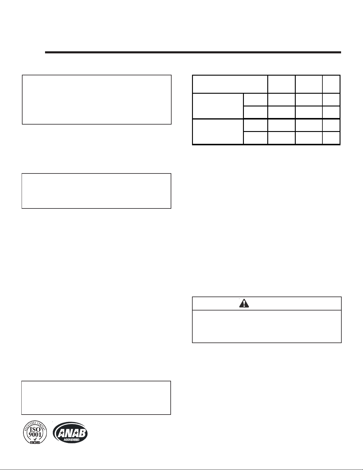
C. BTU Specifications
Models
(U.S. or Canada)
Crescent II (NG)
Crescent II (LP)
US
(0-2000ft.)
CAN
(2000-4500ft.)
US
(0-2000ft.)
CAN
(2000-4500ft.)
Maximum
Input BTUH
11,500 8,500 52
10,350 7,650 53
11,500 N/A 61
10,350 N/A 62
Minimum
Input BTUH
Orifice
Size
(DMS)
D. High Altitude Inst allations
U.L. Listed gas appliances are tested and approved without
requiring changes for elevations from 0 to 2000 feet in the
U.S.A. and Canada.
When installing this appliance at an elevation above 2000
feet, it may be necessary to decrease the input rating by
changing the existing burner orifice to a smaller size. Input
rate should be reduced by 4% for each 1000 feet above a
2000 foot elevation in the U.S.A., or 10% for elevations
between 2000 and 4500 feet in Canada. If the heating value
of the gas has been reduced, these rules do not apply . To
identify the proper orifice size, check with the local gas
utility.
If installing this appliance at an elevation above 4500 feet
(in Canada), check with local authorities.
This statement is in compliance with CPSC 16 CFR
Section 1201.5 “Certification and labeling requirements”
which refers to 15 U.S. Code (USC) 2063 stating “…Such
certificate shall accompany the product or shall otherwise
be furnished to any distributor or retailer to whom the
product is delivered.”
Some local building codes require the use of tempered
glass with permanent marking in such locations. Glass
meeting this requirement is available from the factory.
Please contact your dealer or distributor to order .
NOTE: This installation must conform with local codes. In the
absence of local codes you must comply with the National
Fuel Gas Code, ANSI Z223.1-latest edition in the U.S.A.
and the CAN/CGA B149 Installation Codes in Canada.
Heat & Glo Quality Systems
registered by SGS ICS
Heat & Glo • Crescent II • 2083-902 Rev. G • 9/054
W ARNING
Do NOT use this appliance if any part has been under
water. Immediately call a qualified service technician to
inspect the appliance and to replace any part of the control
system and any gas control which has been under water.
Page 5
2
Getting Started
A. Design and Installation Considerations
Heat & Glo direct vent gas appliances are designed to operate with all combustion air siphoned from outside of the
building and all exhaust gases expelled to the outside. No
additional outside air source is required.
CAUTION
Check building codes prior to installation.
• Installation MUST comply with local, regional, state
and national codes and regulations.
• Consult local building, fire officials or authorities
having jurisdiction about restrictions, installation
inspection, and permits.
When planning an appliance installation, it’s necessary to
determine the following information before installing:
• Where the appliance is to be installed.
• The vent system configuration to be used.
• Gas supply piping.
• Electrical wiring.
• Framing and finishing details.
• Whether optional accessories—devices such as a fan,
wall switch, or remote control—are desired.
C. Inspect Appliance and Component s
WARNING
Inspect appliance and components for
damage. Damaged parts may impair safe
operation.
• Do NOT install damaged components.
• Do NOT install incomplete components.
• Do NOT install substitute components.
Report damaged parts to dealer.
• Carefully remove the appliance and components from
the packaging.
• The vent system components and trim doors are shipped
in separate packages.
• The gas logs may be packaged separately and must be
field installed.
• Report to your dealer any parts damaged in shipment,
particularly the condition of the glass.
• Read all of the instructions before starting the installation. Follow these instructions carefully during the installation to ensure maximum safety and
benefit.
W ARNING
Keep appliance dry.
• Mold or rust may cause odors.
• Water may damage controls.
• Installation and use of any damaged appliance or vent
system component.
B. Tools and Supplies Needed
Before beginning the installation be sure that the following
tools and building supplies are available.
Reciprocating saw Framing material
Pliers Hi temp caulking material
Hammer Gloves
Phillips screwdriver Framing square
Flat blade screwdriver Electric drill and bits (1/4 in.)
Plumb line Safety glasses
Level 1/2 - 3/4 inch length, #6 or #8 Self-drilling screws
Manometer Voltmeter
T ape measure Noncorrosive leak check solution
One 1/4 inch female connection (for optional fan).
Heat & Glo • Crescent II • 2083-902 Rev. G • 9/05
• Modification of the appliance or vent system.
• Installation other than as instructed by Hearth & Home
Technologies.
• Improper positioning of the gas logs or the glass door.
• Installation and/or use of any component part not
approved by Hearth & Home Technologies.
Any such action may cause a fire hazard.
W ARNING
Hearth & Home Technologies disclaims
any responsibility for, and the warranty will
be voided by, the following actions:
5
Page 6
3
Framing and Clearances
NOTE:
• Illustrations reflect typical installations and are FOR
DESIGN PURPOSES ONLY.
• Illustrations/diagrams are not drawn to scale.
• Actual installation may vary due to individual design
preference.
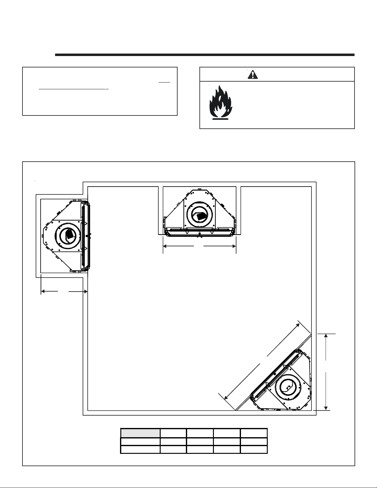
A. Selecting Appliance Location
When selecting a location for your appliance it is important
to consider the required clearances to walls (see Figure 3.1).
W ARNING
Fire Risk
Provide adequate clearance:
• Around air openings
• To combustibles
• For service access
Locate appliance away from traffic areas.
NOTE: For actual appliance dimensions refer to Section 16.
B
D
Figure 3.1 Framing Dimensions
In addition to these framing dimensions, also reference the
following sections:
• Clearances and Mantel Projections (Section 3.C and 3.D)
• Vent Clearances and Framing (Section 6)
C
ABCD
Inches
Millimeters
24-5/8 23-1/2 34-7/8 15-1/8
625 597 886 384
A
Heat & Glo • Crescent II • 2083-902 Rev. G • 9/056
Page 7

B. Constructing the Appliance Chase
A chase is a vertical boxlike structure built to enclose the
gas appliance and/or its vent system. Vertical vents that
run on the outside of a building may be, but are not required to be, installed inside a chase.
or stuffed with unfaced insulation. If the appliance is being
installed on a cement slab, a layer of plywood may be placed
underneath to prevent conducting cold up into the room.
C. Clearances
Construction of the chase may vary with the type of building.
These instructions are not substitutes for the requirements of
local building codes. Local building codes MUST be checked.
Chases should be constructed in the manner of all outside
walls of the home to prevent cold air drafting problems.
The chase should not break the outside building envelope
in any manner.
Walls, ceiling, base plate and cantilever floor of the chase
should be insulated. Vapor and air infiltration barriers should
be installed in the chase as per regional codes for the rest
of the home. Additionally, in regions where cold air infiltration may be an issue, the inside surfaces may be sheetrocked
and taped for maximum air tightness.
To further prevent drafts, the firestops should be caulked
with high temperature caulk to seal gaps. Gas line holes
and other openings should be caulked with high temp caulk
3/4 in.
WARNING
Fire Risk.
Odor Risk.
• Install appliance on hard metal or wood
surfaces extending full width and depth of
appliance.
• Do NOT install appliance directly on
carpeting, vinyl, tile or any combustible
material other than wood.
WARNING
Fire Risk.
• Construct chase to all clearance
specifications in manual.
• Locate and install appliance to all
clearance specifications in manual
A
ABCDE F GHI
Rough
Opening
(Vent Pipe)
Inches
mm 25 4 940 397 622 686 0 0 13 13
Figure 3.2 Clearances to Combustibles
10 37 15-5/8 24-1/2 27 0 0 1/2 1/2
Rough
Opening
(Height)
FROM
BOTTOM
OF HOOD
E
G
I
C
H
CLEARANCES TO COMBUSTIBLES:
Rough
Opening
(Depth)
Rough
Opening
(Width)
Clearance
to Ceiling
Non-Combustible
Floor
Using facing material totalling 3/4 inch thick.
Combustible
Flooring
D
Behind
Appliance
B
Sides of
Appliance
Heat & Glo • Crescent II • 2083-902 Rev. G • 9/05
7
Page 8
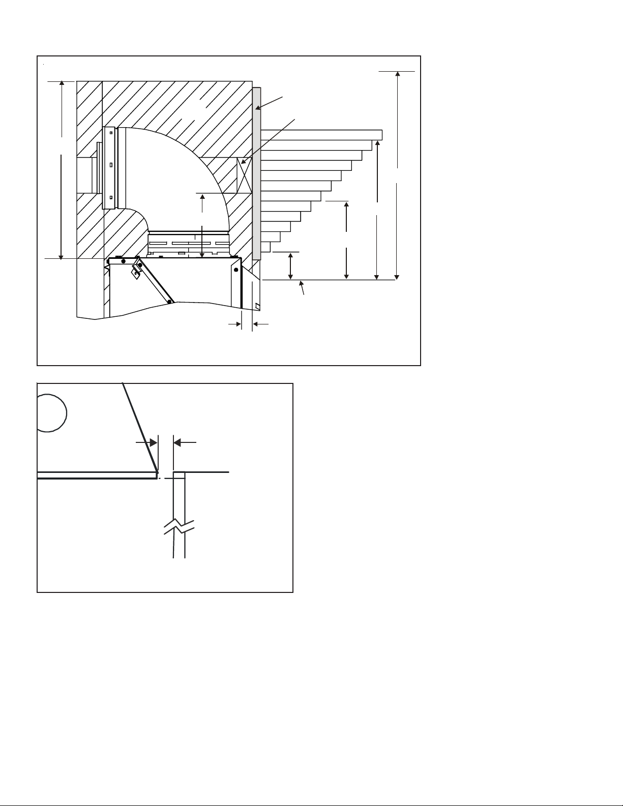
D. Mantel Projections
16-1/4 IN.
AIR
SPACE
6-5/16 IN.
COMBUSTIBLE
SHEATHING
HEADER BOARD
10
9
8
7
6
5
4
3
2
1
2-3/4 IN.
FROM BOTTOM OF HOOD
(VISIBLE WITH DOOR REMOVED)
1 in.
CEILING
12
11
27 IN.
13-3/4 IN.
7-3/4 IN.
Figure 3.3 Clearances to Mantels or other
Combustibles above Appliance
Top View
½ Inch
MANTEL
LEG
Figure 3.4 Clearances to Mantel Legs or Wall Projections
(Acceptable on both sides of opening.)
Note: All measurements
in inches.
Heat & Glo • Crescent II • 2083-902 Rev. G • 9/058
Page 9
4
V
Termination Locations
A. Vent Termination Minimum Clearances
W ARNING
Fire Risk.
Explosion Risk.
Maintain vent clearance to combustibles
as specified.
• Do not pack air space with insulation or
other materials.
Failure to keep insulation or other materials
away from vent pipe may cause fire.
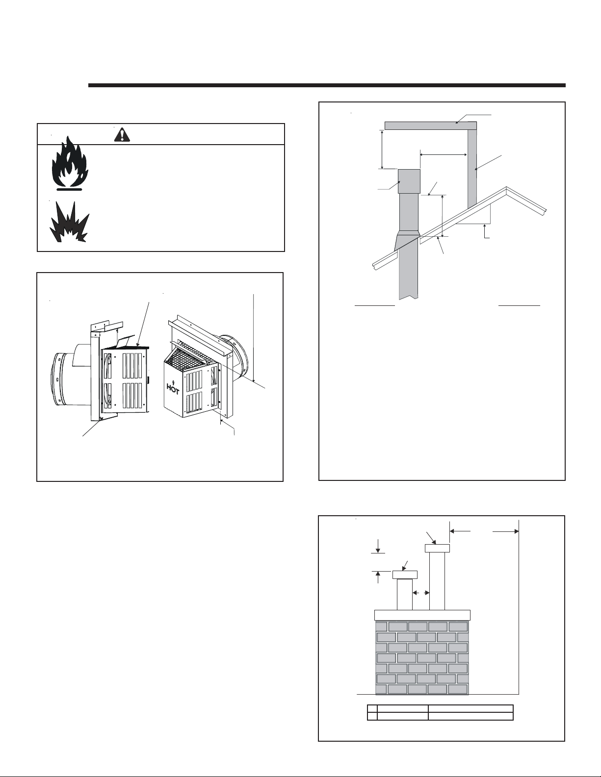
Measure vertical clearances from this surface.
Measure horizontal clearances from this surface.
(See Figure 4.4 for specific clearances)
Figure 4.1
2 FT .
MIN.
TERMINATION
CAP
Roof Pitch H (Min.) Ft.
Flat to 6/12 .........................................................1.0*
6/12 to 7/12 ........................................................1.25*
Over 7/12 to 8/12 ............................................... 1.5*
Over 8/12 to 9/12 ............................................... 2.0*
Over 9/12 to 10/12 ............................................. 2.5
Over 10/12 to 11/12 ........................................... 3.25
Over 11/12 to 12/12 ........................................... 4.0
Over 12/12 to 14/12 ........................................... 5.0
Over 14/12 to 16/12 ........................................... 6.0
Over 16/12 to 18/12 ........................................... 7.0
Over 18/12 to 20/12 ........................................... 7.5
Over 20/12 to 21/12 ........................................... 8.0
* 3 foot minimum in snow regions
Figure 4.2 Minimum Height from Roof to
Lowest Discharge Opening
20 INCHES
LOWEST
DISCHARGE
OPENING
12
H (MIN.) - MINIMUM HEIGHT FROM ROOF
TO LOWEST DISCHARGE OPENING
HORIZONTAL
OVERHANG
ERTICAL
WALL
X
ROOF PITCH
IS X/ 12
Figure 4.2 specifies minimum vent heights for various
pitched roofs.
GAS, WOOD or FUEL
OIL TERMINATION
GAS
TERMINATION
18 IN.
A
Gas Termination Wood & Fuel Oil Termination
A 6 in. 20 in.
Figure 4.3 Multiple Vertical Termination
Heat & Glo • Crescent II • 2083-902 Rev. G • 9/05
20 IN.
(MINIMUM) TO
PERPENDICULAR
WALL (GAS ONLY)
9
Page 10

M
V
N
G
v
D
E
v
B
L
v
B
v
F
v
A
B
v
B
v
A
= VENT TERMINAL
V
A = 12 inches ............ clearances above grade, veran-
(See Note 1)
X
= AIR SUPPLY INLET
da, porch, deck or balcony
B = 12 inches ............ clearances to window or door
that may be opened, or to permanently closed window. (Glass)
D* = 18 inches ............. vertical clearance to unventilat-
ed soffit or to ventilated soffit located above the terminal
*30 inches............ for vinyl clad soffits and below
electrical service
F = 9 inches .............. clearance to outside corner
G = 6 inches ............... clearance to inside corner
H = 3 ft. (Canada) ...... not to be installed above a gas
meter/regulator assembly within 3
feet (90cm) horizontally from the
center-line of the regulator
I = 3 ft. (U.S.A.)
6 ft. (Canada)....... clearance to gas service regula-
tor vent outlet
J = 9 inches (U.S.A.)
12 inches (Canada)clearance to non-mechanical air
supply inlet to building or the
combustion air inlet to any other
appliance
R
H
U.S.
(3 FT)
M
I
X
v
J or K
P
Q
(See Note 2)
S
Electrical
V
V
T
Service
D*
V
S
= AREA WHERE TERMINAL IS NOT PERMITTED
K = 3 ft. (U.S.A.)
6 ft. (Canada) ......... clearance to a mechanical
(powered) air supply inlet
L** = 7 ft.......................... clearance above paved side-
(See Note 1)
walk or a paved driveway located on
public property
M*** = 18 inches .............. clearance under veranda, porch,
deck, balcony or overhang
42 inches .............. vinyl
S = 6 inches ................. clearance from sides of
(See Note 5)
electrical service
T = 12 inches ................ clearance above electrical
(See Note 5)
service
Alcove Applications
N = 6 inches................. non-vinyl sidewalls
P = 8 ft.
______________________________________________________________________
______________________________________________________________________
______________________________________________________________________
______________________________________________________________________
12 inches .............. vinyl sidewalls
Q
MIN
R
MAX
1 cap 3 feet 2 x Q
2 caps 6 feet 1 x Q
3 caps 9 feet 2/3 x Q
4 caps 12 feet 1/2 x Q
Q
= # termination caps x 3 R
MIN
= (2 / # termination caps) x Q
MAX
ACTUAL
ACTUAL
ACTUAL
ACTUAL
ACTUAL
** a vent shall not terminate directly above a sidewalk or paved
driveway which is located between two single family dwellings and
serves both dwellings.
*** only permitted if veranda, porch, deck or balcony is fully open on
a minimum of 2 sides beneath the floor, or meets Note 2.
NOTE 1: On private property where termination is less than 7 feet
above a sidewalk, driveway, deck, porch, veranda or balcony, use of
a listed cap shield is suggested. (See vents components page)
NOTE 2: Termination in an alcove space (spaces open only on one side
and with an overhang) are permitted with the dimensions specified for
vinyl or non-vinyl siding and soffits. 1. There must be 3 feet minimum
between termination caps. 2. All mechanical air intakes within 10 feet
of a termination cap must be a minimum of 3 feet below the termination
cap. 3. All gravity air intakes within 3 feet of a termination cap must be
a minimum of 1 foot below the termination cap.
Figure 4.4 Vent Termination Minimum Clearances
NOTE 3: Local codes or regulations may require different
clearances.
NOTE 4: Termination caps may be hot. Consider their proximity
to doors or other traffic areas.
NOTE 5: Location of the vent termination must not interfere with
access to the electrical service.
WARNING: In the U.S: Vent system termination is NOT permit-
ted in screened porches. You must follow side wall, overhang
and ground clearances as stated in the instructions.
In Canada: Vent system termination is NOT permitted in screened
porches. Vent system termination is permitted in porch areas with
two or more sides open. You must follow all side walls, overhang
and ground clearances as stated in the instructions.
Heat & Glo assumes no responsibility for the improper performance of the appliance when the venting system does not meet
these requirements.
CAUTION: IF EXTERIOR WALLS ARE FINISHED WITH VINYL SIDING, IT IS SUGGESTED THAT A VINYL PROTECTOR KIT BE INST ALLED .
Heat & Glo • Crescent II • 2083-902 Rev. G • 9/0510
Page 11
Vent Information and Diagrams
V
5
A. Vent Table Key
The abbreviations listed in this vent table key are used in
the vent diagrams.
Symbol Description
V1
V2
H1
H2
First section (closest to applia nce) of vertical length
Second section of vertical length
First section (closest to appliance) of horizontal length
Sec ond section of horizo ntal l ength
W ARNING
Fire Hazard.
Explosion Risk.
Asphyxiation Risk.
Do NOT connect this gas appliance to a
chimney flue serving a separate solid-fuel or
gas burning appliance.
• Vent this appliance directly outside.
• Use separate vent system for this
appliance.
May impair safe operation of this appliance or
other appliances connected to the flue.
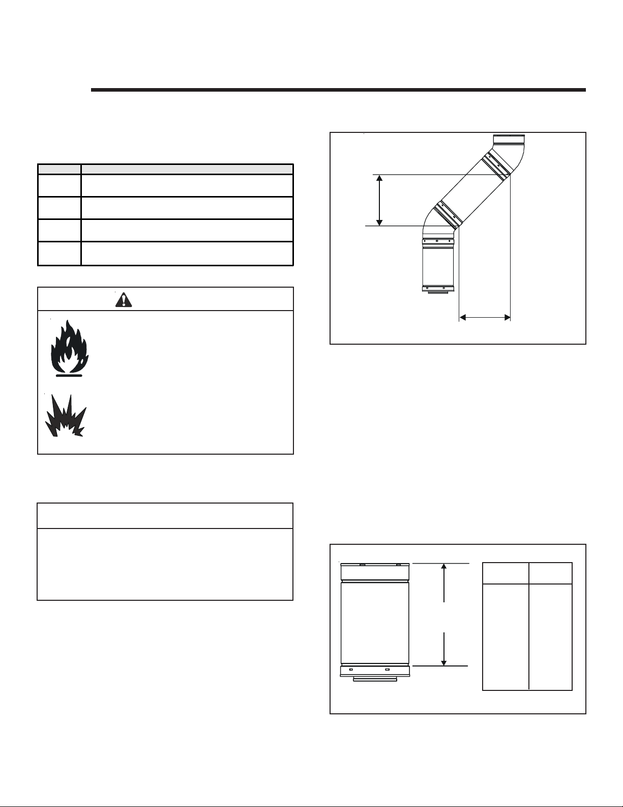
ERTICAL
Figure 5.1
HORIZONTAL
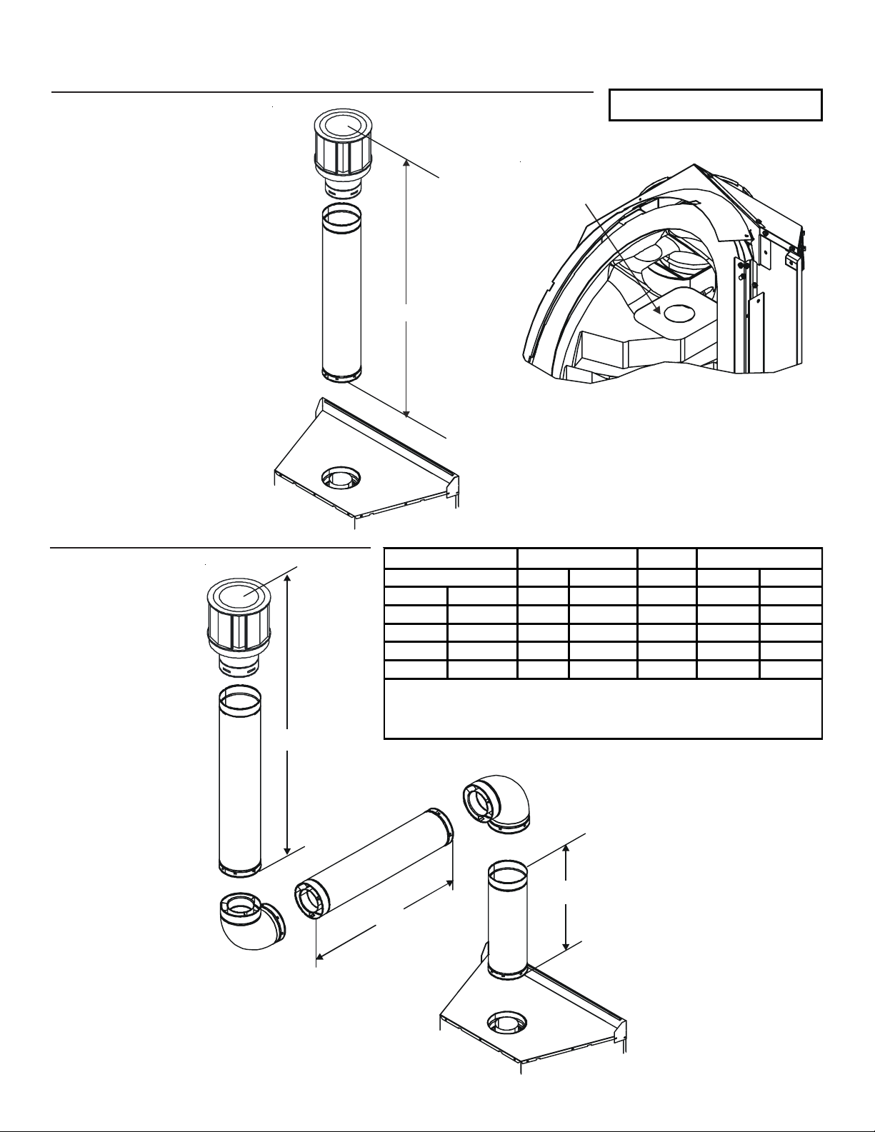
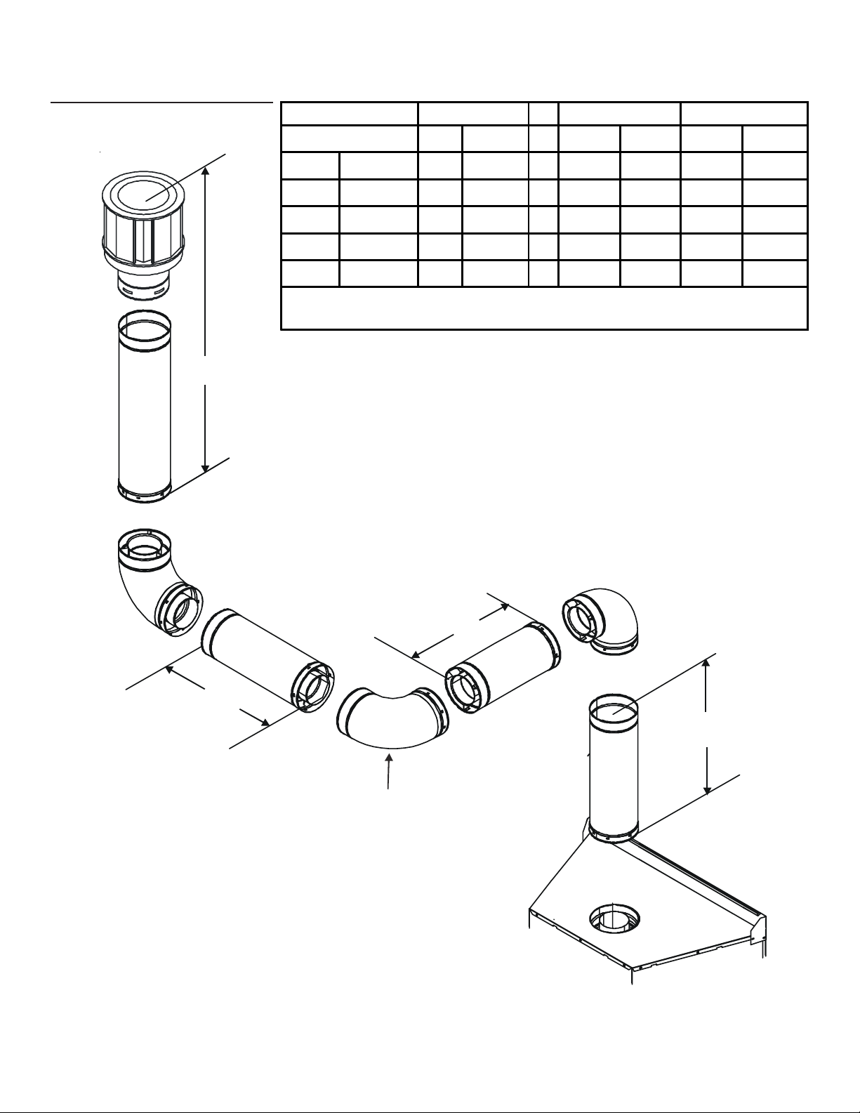
C. Measuring Standards
Vertical and horizontal measurements listed in the vent
diagrams were made using the following standards.
1. Pipe measurements are shown using the effective length
of pipe (see Figure 5.2).
2. Measurements are made from the appliance outer wrap,
not from the standoffs.
B. Use of Elbows
CAUTION
ALL vent configuration specifications MUST be followed.
• This product is tested and listed to these
specifications.
• Appliance performance will suffer if specifications are
not followed.
Diagonal runs have both vertical and horizontal vent aspects when calculating the effects. Use the rise for the vertical aspect and the run for the horizontal aspect (see Figure 5.1).
Two 450 elbows may be used in place of one 900 elbow . On
450 runs, one foot of diagonal is equal to 8.5 inches horizontal run and 8.5 inches vertical run. A length of straight
pipe is allowed between two 450 elbows (see Figure 5.1).
3. Horizontal terminations are measured to the outside
mounting surface (flange of exterior firestop) (see Figure 4.1).
4. V ertical terminations are measured to bottom of termination cap.
Length/
Inches
DVP4 4
DVP6 6
DVP PIPE
Figure 5.2 DVP Pipe Effective Length
Effective
Height/Length
DVP12 12
DVP24 24
DVP36 36
DVP48 48
DVP6A 3 to 6
DVP12A 3 to 12
DVP12MI 3 to 1 2
DVP24MI 3 to 2 4
Pipe
Heat & Glo • Crescent II • 2083-902 Rev. G • 9/05
11
Page 12
D. Vent Diagrams
V
V
Fire Risk. Explosion Risk.
Do NOT pack insulation or other combustibles between firestops.
• ALWAYS maintain specified clearances around venting and firestop systems.
• Install firestops as specified.
Failure to keep insulation or other material away from vent pipe may cause fire.
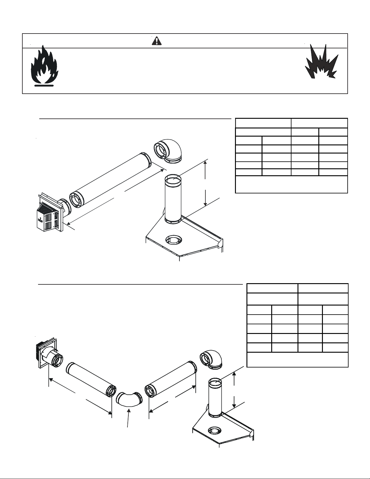
1. Top Vent - Horizontal Termination
One Elbow
H
1
W ARNING
V
Minimum H1 Maximum
1
Elbow only 2 ft 610 mm
6 in 152 mm 2 ft 610 mm
1 1/2 ft 457 mm 3 ft 914 mm
2 1/2 ft 762 mm 5 ft 1.5 m
3 1/2 ft 1067 mm 7 ft 2.1 m
4 1/2 ft 1.4 m 15 ft 4.6 m
V
+ H1 = 38 ft (11.6m) Maximum
1
1
H
= 15 ft (4.6 m) Ma ximum
1
Figure 5.3
Two Elbows
Figure 5.4
H
V1 Minimum H1 + H2 Maximum
0
elbows back
2 - 90
to back
6 in 152 mm 2 610 mm
1 1/2 ft 457 mm 3 ft 914 mm
2 1/2 ft 762 mm 5 ft 1.5 m
3 1/2 ft 1067 mm 7 ft 2.1 m
4 1/2 ft 1.4 m 15 ft 4.6 m
+ H1+ H2 = 38 ft (11.6 m) Maximum
V
1
+ H2 = 15 ft (4.6 m) Maximum
H
1
2
INSTALLED
HORIZONTALLY
H
1
1
Cannot do
Heat & Glo • Crescent II • 2083-902 Rev. G • 9/0512
Page 13

1. Top Vent - Horizontal Termination - (continued)
V
Three Elbows
V
Min. H1 Max. V2 Min. H2 Max.
1
Elbow only 2 ft 610 mm *
1-1/2 ft 457 mm 2 ft 610 mm *
1-1/2 ft 457 mm 3 ft 914 mm *
2-1/2 ft 762 mm 5 ft 1.5 m *
3-1/2 ft 1.06 m 7 ft 2.1 m *
4-1/2 ft 1.4 m 15 ft 4.6 m *
= V
= V
= V
= V
= V
= V
2
2
2
2
2
2
*When using V2 , H2 Max = V2. If V2 = 0, then H2 Max = 1-1/2 ft (38 mm)
(H
+ H2 ) cannot exceed 15 ft (381mm) when using appropriate V2.
1
H
2
V
2
H
1
1
Figure 5.5
Heat & Glo • Crescent II • 2083-902 Rev. G • 9/05
13
Page 14
2. Top Vent - Vertical Termination
V
V
No Elbow
Figure 5.6
V1 = 45 ft Max. (13.7m)
RESTRICTOR
PLATE
1
Note: For vertical venting of 8 feet or higher, the
restrictor plate should be used. The restrictor is
shipped in bottom of fireplace (secured on right
side with a tie strap). Insert the restrictor plate
in center of flue. Once installed in center of flue
turn the restrictor plate so it sits on top of firebox.
Two Elbows
V
1
H1 Maximu m V
V1 + V
2
Minimum
2
One Elbow 2 ft 610 mm * * *
6 in 152 mm 2 ft 610 mm * * *
1 1/2 ft 4 57 mm 3 ft 914 mm * * *
2 1/2 ft 762 mm 5 ft 1 .5 m * * *
3 1/2 ft 1067 mm 7 ft 2.1 m * * *
4 1/2 ft 1.4 m 15 ft 4.6 m * * *
V
+ V2 + H1 = 38 ft (11.6m) Max.
1
*No specific restrictions on this value EXCEPT
+ V2 + H1 cannot exceed 38 ft (11.6m)
V
V
2
H
1
1
1
Figure 5.7
Heat & Glo • Crescent II • 2083-902 Rev. G • 9/0514
Page 15
2. Top Vent - Vertical Termination - (continued)
V
V
Three Elbows
V1 H1+ H
2
V2 V1+ V2 Minimum H1+ H2 Maximum
Elbow only 2 ft 610 mm * * * 3 ft. 914 mm
6 in 152 mm 2 ft 610 mm * * * 7 ft. 2.1 m
1 1/2 ft 457 mm 3 ft. 914 mm * * * 17 ft. 5.2 m
2 1/2 ft 762 mm 5 ft. 1.5 m * * * 5 ft. 1.5 m
3 1/2 ft 1067 mm 7 ft. 2.1 m * * * 7 ft. 2.1 m
4 1/2 ft 1.4 m 15 ft. 4.6 m * * * 15 ft. 4.6 m
+ H2 = 15 ft (4.6m) Maximum
H
1
V
+ V
+ H
1
2
+ H2 = 38 ft (11.6m) Maximum
2
1
H
H
1
2
1
INSTALLED
HORIZONTALLY
Figure 5.8
Heat & Glo • Crescent II • 2083-902 Rev. G • 9/05
15
Page 16

6
Vent Clearances and Framing
A. Pipe Clearances to Combustibles
W ARNING
Fire Risk.
Explosion Risk.
Maintain vent clearance to combustibles
as specified.
• Do not pack air space with insulation or
other materials.
Failure to keep insulation or other materials
away from vent pipe may cause fire.
3 in. TOP
NOTE: No
slope required.
1 in. CLEARANCE
AROUND VERTICAL
SECTIONS
CLEARANCE
1 in. SIDE AND
BOTTOM CLEARANCE
B. Wall Penetration Framing
40-7/8 in.*
* Shows center of vent framing hole for top venting.
The center of the hole is one (1) inch (25.4mm)
above the center of the horizontal vent pipe.
Figure 6.2 Exterior Wall Hole
39-7/8 in.
Figure 6.1 Pipe Clearances
Combustible Wall Penetration
Frame a hole in a combustible wall for an interior wall shield,
(Figure 6.2) whenever a wall is penetrated. Use same size
framing materials as those used in the wall construction.
The wall shield maintains minimum clearances and prevents cold air infiltration.
Non-Combustible Wall Penetration
If the hole being penetrated is surrounded by noncombustible materials such as concrete, a hole with diameter one
inch greater than the pipe is acceptable.
Heat & Glo • Crescent II • 2083-902 Rev. G • 9/0516
Page 17

C. Vertical Penetration Framing
G
W ARNING
Fire Hazard
Keep loose materials or
blown insulation from touching the vent pipe.
• National building codes recommend us-
ing attic shield to keep loose materials/
blown insulation from contacting vent.
• Hearth & Home Technologies requires
the use of an attic shield.
ATTIC
ABOVE
Installing the Firestop Sp acer
• Frame an opening 10 inches by 10 inches whenever the vent system penetrates a ceiling/floor (see Figure 6.3).
• Frame the area with the same sized lumber as used in ceiling/floor joist.
• When installing a top vent vertical appliance the hole should be directly above
the appliance, unless the flue is offset.
• Do not pack insulation around the vent.
Insulation must be kept away from the
pipe.
A
B
A B
DVP
10 in. 10 in.
PIPE
Installing Attic Shield
Note: The firestop spacer is not required if
attic shield is used.
• Frame opening for attic shield.
• Attic shield may be installed above or
below ceiling (see Figure 6.4).
• Secure with three fasteners on each
side.
• Fold tabs at top of attic shield in toward
vent pipe. Tabs must keep vent pipe
centered within shield.
• Field construct additional shield height
if insulation is deeper than height of attic shield.
Figure 6.3
BEND TABS IN
AROUND PIPE
3 FASTENERS
PER SIDE
ATTIC SHIELD INSTALLED
BELOW CEILIN
Figure 6.4 Installing the Attic Shield
Heat & Glo • Crescent II • 2083-902 Rev. G • 9/05
ATTIC SHIELD INSTALLED
ABOVE CEILING
17
Page 18

Appliance Preparation
7
A. Securing and Leveling the Appliance
WARNING
Fire Risk.
• Prevent contact with sagging, loose
insulation.
• Do NOT install against vapor barriers or
exposed insulation.
CAUTION
Sharp Edges
• Wear protective gloves
and safety glasses
during installation.
The diagram shows how to properly position, level, and secure the appliance (see Figure 7.1). Nailing tabs are provided to secure the appliance to the framing members.
NAILING
TAB
TOP
VIEW
FRONT
VIEW
REMOVE
SCREWS (2)
REFASTEN
DETAIL A
NAILING
TAB
BACK
VIEW
SCREWS (2)
NAILING TABS
BOTH SIDES
2 HOLES I N BASE FOR
MOUNTING TO FLOOR
Figure 7.1 Proper Positioning, Leveling and
Securing of a Appliance
• Place the appliance into position.
• Level the appliance from side to side and front to back.
• Shim the appliance with noncombustible material, such
as sheet metal, as necessary.
Î
• Remove two side screws from each nailing tab (see
Figure 7.2) and refasten nailing tabs to the appliance.
Note: Return bend on nailing tab faces back of unit.
• Keep nailing tabs flush with the framing.
• Secure the appliance to the framing by using nails or screws
through the nailing tabs.
• Holes are also provided in appliance bottom to secure
appliance to floor.
Heat & Glo • Crescent II • 2083-902 Rev. G • 9/0518
RETURN BEND FACES
THE BACK OF THE UNIT
Figure 7.2 Nailing tabs
WARNING
Fire Risk.
• ALWAYS maintain specified
clearances around the appliance.
• Do NOT notch into the framing around the appliance spacers.
Failure to keep insulation, framing or other material away
from the appliance may cause fire.
Í
Page 19

Installing Vent Pipe
8
A. Assembly of Vent Sections
WARNING
Fire Risk
Exhaust Fumes Risk
Impaired Performance of Appliance
• Overlap pipe slip sections at least 1-1/2 inches.
• Use pilot holes for screws.
• Screws must not exceed one inch long.
• Pipe may separate if not properly joined.
Attaching V ent to the Firebox Assembly
To attach the first pipe section to the collars, slide the male end of
the inner vent of the pipe section over the inner collar on the firebox
assembly. At the same time, slide the outer flue over the outer
collar on the appliance. Push the pipe section into the appliance
collar until all the lances (see Figure 8.1) have snapped in place.
Tug slightly on the section to confirm it has completely locked into
place.
Assembling Pipe Sections
Insert the inner flue of section A into the flared inner flue of section B.
Start the outer flue of section A over the outer flue of section B (see
Figure 8.2). Note: The end of the pipe sections with the lances/tabs
on it will face towards the appliance.
Once both inner and outer flues
are started, press section A onto
section B firmly until all lances
have snapped into place. Check
to make sure they have
snapped together (see Figure
8.3) and the seams are not
aligned (see Figure 8.4). Tug
slightly on section A to confirm
it has completely locked into
place.
Note: Make sure that the seams are not aligned to prevent unintentional disconnection.
Figure 8.1 Lances
A
B
Figure 8.2
Figure 8.3
For 90° and 45° elbows that are
changing the vent direction from
horizontal to vertical, one screw
minimum should be put in the
outer flue at the horizontal elbow
joint to prevent the elbow from
rotating.
CORRECT
Figure 8.4 Seams
Heat & Glo • Crescent II • 2083-902 Rev. G • 9/05
INCORRECT
19
Page 20

Assembling Minimum Installations (MI) Sections
MI sections are non-unitized so that they can be cut to a
certain length. Cut these sections to length from the nonexpanded end (see Figure 8.5).
They can then be attached by first connecting the expanded
end of the MI inner flue with the inner pipe from the adjacent
pipe section and securing with three screws. The expanded
portion of the MI inner flue must overlap completely with
the unexpanded end of the adjacent pipe section.
The outer flue can then be inserted into the adjacent outer
flue expanded end and attached to the next pipe section
with three screws. The other end of the MI pipe section
can then be attached by fitting another pipe section to it
and snapping it together, as normal.
Assembling DVP-12A Slip Sections
The outer flue of the slip section should slide over the outer
flue of the pipe section and into (inner flue) the last pipe
section (see Figure 8.6) .
Figure 8.5
Slide together to the desired length, making sure that a
1-1/2 inch outer flue overlap is maintained between the
pipe section and slip section.
The pipe and slip section need to be secured by driving
two screws through the overlapping portions of the outer
flues using the pilot holes (see Figure 8.7).
This will secure the slip section to the desired length and
prevent it from separating. The slip section can then be
attached to the next pipe section.
If the slip section is too long, the inner and outer flues of
the slip section can be cut to the desired length.
Figure 8.6 Slip Section Pilot Holes
Figure 8.7 Screws into Slip Section
Heat & Glo • Crescent II • 2083-902 Rev. G • 9/0520
Page 21

Securing the Vent Sections
Vertical Sections
Vertical sections of pipe must be supported every 8 feet
after the 25 foot maximum unsupported rise. The vent
support or plumber’s strap (spaced 120° apart) may be
used to do this (see Figure 8.8).
Horizontal Sections
Horizontal sections of vent must be supported every 5 feet
with a vent support or plumber’s strap.
Figure 8.8 Securing Vertical Pipe Sections
B. Disassembly of Vent Sections
T o disassemble any two pieces of pipe, rotate either section
(see Figure 8.10), so that the seams on both pipe sections
are aligned (see Figure 8.11). They can then be carefully
pulled apart.
W ARNING
Fire Risk.
Explosion Risk.
Combustion Fume Risk.
Use vent run supports per installation
instructions.
Connect vent sections per installation
instructions.
• Maintain all clearances to combustibles.
• Do NOT allow vent to sag below
connection point to appliance.
• Maintain specified slope (if required).
Improper support may allow vent to sag or separate.
Figure 8.9 Securing Horizontal Pipe Sections
Figure 8.10 Rotate Seams for Disassembly
Figure 8.11 Align and Disassemble Vent Sections
Heat & Glo • Crescent II • 2083-902 Rev. G • 9/05
21
Page 22

C. Installing Heat Shield and Horizontal Termination Cap
W ARNING
Fire Hazard
Impaired performance of appliance
• Telescoping flue section of termination cap
MUST be used when connecting pipe
section to termination cap.
• Maintain a 1-1/2 inch minimum overlap on
telescoping flue section of termination cap.
WARNING
Fire Risk
Exhaust Fumes Risk
Impaired Performance of Appliance
• Overlap pipe slip sections at least 2 inches.
• Use pilot holes for screws.
• Screws must not exceed 1 inch long.
• Pipe may separate if not properly joined.
Heat Shield Requirements for Horizont al Termination
Installing the Horizontal Termination Cap
Vent termination must not be recessed in the wall. Siding
may be brought to the edge of the cap base.
Caulk the outside edges of the cap (see Figure 8.12).
When installing a horizontal termination cap, follow the cap
location guidelines as prescribed by current ANSI Z223.1
and CAN/CGA-B149 inst allation codes.
WARNING
Burn Risk
• Local codes may require installation of
a cap shield to prevent anything or
anyone from touching the hot cap.
HEAT SHIELD OR
EXTENDED
HEAT SHIELD
REAR VENT
HEAT SHIELD
WALL SHIELD
1-1/2 IN. MIN.
OVERLAP
For all horizontally vented appliances, a heat shield MUST
be placed one inch above the top of the vent between the
wall shield and the base of the termination cap.
There are two sections of the heat shield. One section
attaches to the wall shield with two screws. The remaining
section is attached to the cap in the same manner .
If the wall thickness does not allow the required 1-1/2 inch
heat shield overlap, an extended heat shield must be used.
The extended heat shield will need to be cut to the
thickness of the wall and be attached to the wall shield.
The small leg on the extended heat shield should rest on
the top of the vent (pipe section) to properly space it from
the pipe section (see Figure 8.12).
INNE R V ENT
OUTER VENT
INTERIOR
Figure 8.12 Venting through the Wall
EXTERIOR
SHEATHING
NOTE: Where required, an exterior wall flashing is
available.
When penetrating a brick wall, a brick extension kit
is available for framing the brick.
Heat & Glo • Crescent II • 2083-902 Rev. G • 9/0522
Page 23

D. Installing Roof Flashing and
V
Vertical Termination Cap
To install roof flashing see Figure 8.13.
For installation of vertical termination cap see minimum
vent heights for various pitched roofs (see Figure 8.13) .
HORIZONTAL
OVERHANG
T o attach the vertical termination cap, slide the inner collar
of the cap into the inner flue of the pipe section and place
the outer collar of the cap over the outer flue of the pipe
section.
Secure with three screws into the outer flue. Secure the cap
by driving the three self-tapping screws (supplied) through
the pilot holes in the outer collar of the cap into the outer flue
of the pipe (see Figure 8.14).
2 FT .
MIN.
TERMINATION
CAP
20 INCHES
LOWEST
DISCHARGE
OPENING
H (MIN.) - MINIMUM HEI GHT FROM ROOF
TO LOWEST DISCHARGE OPE NING
Roof Pitch H (Min.) Ft.
Flat to 6/12...................................... 1.0*
6/12 to 7/12 .................................. 1.25*
Over 7/12 to 8/12........................... 1.5*
Over 8/12 to 9/12........................... 2.0*
Over 9/12 to 10/12.......................... 2.5
Over 10/12 to 11/12...................... 3.25
Over 11/12 to 12/12........................ 4.0
Over 12/12 to 14/12........................ 5.0
Over 14/12 to 16/12........................ 6.0
Over 16/12 to 18/12........................ 7.0
Over 18/12 to 20/12........................ 7.5
Over 20/12 to 21/12........................ 8.0
X
12
ROOF PITCH
IS X/ 12
ERTICAL
WALL
(1 of 3)
CAULK
Figure 8.14 Termination Cap - DVP-TVHW
TERMINATION CAP
STORM
COLLAR
SCREWS
* 3 foot minimum in snow regions
Figure 8.13 Minimum Height from Roof to
Lowest Discharge Opening
W ARNING
Fire Risk.
Explosion Risk.
Inspect external vent cap regularly.
• Ensure no debris blocks cap.
• Combustible materials blocking cap may
ignite.
• Restricted air flow affects burner operation.
Heat & Glo • Crescent II • 2083-902 Rev. G • 9/05
23
Page 24

Assembling and Installing Storm Collar
CAUTION
Sharp Edges
• Wear protective gloves
and safety glasses
during installation.
Connect both halves of the storm collar with two screws
(see Figure 8.15).
Wrap the storm collar around the exposed pipe section
and align brackets. Insert a bolt (provided) through the
brackets and tighten nut to complete storm collar assembly
(see Figure 8.16).
Slide the assembled storm collar down the pipe section
until it rests on the roof flashing.
Caulk around the top of the storm collar (see Figure 8.14).
Figure 8.16 Assembling the Storm Collar Around the Pipe
Figure 8.15 Assembling the Storm Collar
Heat & Glo • Crescent II • 2083-902 Rev. G • 9/0524
Page 25

9
Gas Information
A. Fuel Conversions
Before making gas connections ensure that appliance
being installed is compatible with the available gas type.
Any natural or propane gas conversions necessary to meet
the appliance and locality needs must be made by a qualified technician using Hearth & Home Technologies specified and approved parts.
B. Gas Pressures
Proper input pressures are required for optimum appliance
performance. Gas line sizing requirements need to be made
following NFP A51.
WARNING
Fire Risk.
Explosion Hazard.
High pressure will damage valve.
• Disconnect gas supply piping BEFORE
pressure testing gas line at test pressures
above 1/2 psig.
• Close the manual shutoff valve BEFORE
pressure testing gas line at test pressures
equal to or less than 1/2 psig.
C. Gas Connection
NOTE: Have the gas supply line installed in accordance
with local building codes, if any. If not, follow ANSI 223.1.
Installation should be done by a qualified installer approved
and/or licensed as required by the locality. (In the
Commonwealth of Massachusetts installation must be
performed by a licensed plumber or gas fitter.)
NOTE: A listed (and Commonwealth of Massachusetts approved) 1/2 inch (13mm) T-handle manual shut-of f valve and
flexible gas connector are connected to the 1/2 inch (13mm)
control valve inlet.
• If substituting for these components, please consult
local codes for compliance.
Refer to Reference Section 16 for location of gas line access in appliance.
NOTE: Gas line may be run from either side of the
appliance
exceed 2-1/2
the firebox.
provided the hole in the outer wrap does NOT
inches in diameter and does not penetrate
WARNING
WARNING
Verify inlet pressures.
• High pressure may cause overfire
condition.
• Low pressure may cause explosion.
• Verify minimum pressures when other
household gas appliances are operating.
Install regulator upstream of valve if line
pressure is greater than 1/2 psig.
Pressure requirements for appliance are shown in the table
below. Minimum pressures must be met when other
household gas appliances are operating.
Pressure Natural Gas Propane
Minimum 5.0 inches 11.0 inches
Inlet Pressure w.c. w.c.
Maximum Inlet 14.0 inches 14.0 inches
Gas Pressure w.c. w.c.
Manifold 3.5 inches 10.0 inches
Pressure w.c. w.c.
Gas Leak Risk
• Support control when attaching pipe to
prevent bending gas line.
Heat & Glo • Crescent II • 2083-902 Rev. G • 9/05
25
Page 26

• Ensure that gas line does not come in contact with outer
wrap of appliance. Follow local codes.
HIGH AL TITUDE INST ALLATIONS
• Incoming gas line should be piped into the valve compartment and connected to the 1/2 inch connection on
the manual shutoff valve.
WARNING
Fire or Explosion Hazard
• Gas buildup during line purge may ignite.
• Purge should be performed by qualified technician.
• Ensure adequate ventilation.
• Ensure there are no ignition sources such as
sparks or open flames.
• A small amount of air will be in the gas supply lines.
When first lighting appliance it will take a short time for
air to purge from lines. When purging is complete the
appliance will light and operate normally .
WARNING
CHECK FOR GAS LEAKS
Explosion Risk
Fire Risk
Asphyxiation Risk
• Check all fittings and connections.
• Do not use open flame.
• After the gas line installation is complete,
all connections must be tightened and
checked for leaks with a commercially-
available, non-corrosive leak check solution. Be sure
to rinse off all leak check solution following testing.
Fittings and connections may have loosened during
shipping and handling.
U.L. Listed gas appliances are tested and approved
without requiring changes for elevations from 0 to
2000 feet in the U.S.A. and Canada.
When installing this appliance at an elevation above
2000 feet, it may be necessary to decrease the input
rating by changing the existing burner orifice to a
smaller size. Input rate should be reduced by 4% for
each 1000 feet above a 2000 foot elevation in the
U.S.A., or 10% for elevations between 2000 and 4500
feet in Canada. If the heating value of the gas has
been reduced, these rules do not apply. To identify
the proper orifice size, check with the local gas utility .
If installing this appliance at an elevation above 4500
feet (in Canada), check with local authorities.
WARNING
Fire hazard.
Do NOT change the valve settings.
• This valve has been preset at the factory.
• Changing valve settings may result in fire
hazard or bodily injury.
Heat & Glo • Crescent II • 2083-902 Rev. G • 9/0526
Page 27

10
Electrical Information
A. Recommendation for Wire
This appliance requires 110-120 V AC be wired to the junction
box for proper operation of the appliance (Intellifire ignition).
NOTE: This appliance must be electrically wired and
grounded in accordance with local codes or, in the absence
of local codes, with National Electric Code ANSI/NFP A 70-
latest edition or the Canadian Electric Code, CSA C221.1.
B. Connecting to the Appliance
WARNING
Wire 110V to electrical junction box.
Do NOT wire 110V to valve.
Do NOT wire 110V to wall switch.
• Incorrect wiring will damage millivolt valves.
• Incorrect wiring will override IPI safety
lockout and may cause explosion.
• This appliance may be used with a wall switch, wall
mounted thermostat and/or a remote control.
• If using thermostat use one compatible with a millivolt
gas valve system.
C. Intellifire Ignition System Wiring and
3 Function Circuit Board
This appliance requires a 1 10 V AC supply to the appliance
junction box for operation. A wiring diagram is shown in
Figure 10.1.
This appliance is equipped with an Intellifire control valve
which operates on a 3 volt system.
This appliance is equipped with a 3 function circuit board
which operates on 1 10 V AC and 12 VDC.
This appliance is supplied with a 3 volt AC transformer and
a 12 volt DC transformer, which requires the inst allation of
the supplied junction box. It is highly recommended that
the junction box be installed at this time to avoid
reconstruction.
Optional Remote Control Requirements
T o attach remote receiver in series with 3 function wall switch
see wiring diagram (Figure 10.2).
CAUTION
Label all wires prior to disconnection when servicing controls. Wiring errors can cause improper and dangerous
operation. Verify proper operation after servicing.
• Follow parameters for locating thermostat (see individual
thermostat instructions) to ensure proper operation of
appliance.
• Use low resistance thermostat wire for wiring from ignition system to the wall switch and thermostat.
• Keep wire lengths short as possible by removing any
excess wire length.
• Low voltage and 110 VAC voltage cannot be shared
within the same wall box.
W ARNING
Shock hazard.
• Replace damaged wire with type 105O C
rated wire.
• Wire must have high temperature insulation.
Heat & Glo • Crescent II • 2083-902 Rev. G • 9/05
27
Page 28

Figure 10.1 Intellifire Pilot Ignition (IPI) Wiring Diagram - Standard Method
12VDC
Wire terminal latch can become
damaged if excessive force is used
when releasing wire. Please use
caution in pressing retainer.
PRESS. SW
IPI
50-0253 02-D
PLUG-IN
J-BOX
CAUTION
CIRCUIT BOARD
P2
COMC1C2
R1
D3
T16
R1
T15
K1
T2
C1
T1
SOLENOID
CANADA
MADE IN
HIHI
12V
J1J1
D1
D2
R4
EMBER
T6
T5
P1
REM
K2
LINE NEU
T14
REM
OFF/ON
++
C2
K3
HI/LOW
1C
1
C
EMBER LIGHTS
T13
T13
T12
T12
3
3
T11
T11
T10
2
T9
GREEN
BLACK
RED
SWITCH
YELLOW
PLUGGED INTO
ANY OF #1 - #5
BLACK WIRE
LOCATIONS
HOT SIDE
CAN BE
ON THE
J-BOX
2
PLUGGED INTO
NEUTRAL SIDE
ANY OF #1 - #5
WHITE WIRE
LOCATIONS
CAN BE
ON THE
PLUG-IN
TRANSFORMER
J-BOX
3 VAC
WHITE
BLACK
SOLENOID (NG ONLY)
BROWN
BROWN
GROUND TO
ORG
FIREPLACE CHASSIS
ORG
WHT
LIGHT SOCKET
S
IGNITION MODULE 3 VAC
I
INTERMITTENT PILOT IGNITOR
VALVE
GRN
*Note: Appliance will not operate unless properly grounded.
Heat & Glo • Crescent II • 2083-902 Rev. G • 9/0528
Page 29

GRN
VALVE
WHT
INTERMITTENT PILOT IGNITOR
I
S
ORG
GROUND TO
ORG
FIREPLACE CHASSIS
LIGHT SOCKET
IGNITION MODULE 3 VAC
BROWN
BROWN
SOLENOID (NG ONLY)
WHITE
BLACK
WHITE WI RE
CAN BE
ON THE
NY OF #1 - #5
LOCATIONS
PLUGGED INTO
3 VA C
TRANSFORMER
NEUTRAL SIDE
J-BOX
PLUG-IN
2
J-BOX
SWITCH
ON THE
CAN BE
HOT SIDE
LOCATIONS
BLACK WIRE
ANY OF #1 - #5
PLUGGED INTO
RED
YELLOW
BLACK
GREEN
3
3
C
1
1C
T9
HI/LOW
2
K3
T10
T11
T11
T12
T12
C2
++
T13
T13
EMBER LIGHT S
OFF/ON
REM
T14
P1
T5
EMBER
T6
LINE NEU
K2
J1J1
HIHI
REM
SOLENOID
R4
D2
D1
12V
COMC1C2
50-025302-D
MADE IN
CANADA
T1
C1
IPI
T2
K1
T15
R1
PRESS. SW
T16
D3
R1
P2
REMOTE RECEIVER
PLUG-IN
J-BOX
12VDC
Heat & Glo • Crescent II • 2083-902 Rev. G • 9/05
CIRCUIT BOARD
Figure 10.2 Intellifire Pilot Ignition (IPI) Wiring Diagram with optional remote wired in series
29
Page 30

D. Junction Box Installation
X
It is recommended to wire the unit from outside
the appliance.
• Remove the junction box assembly located on
the outer shell - right side (see Figure 10.3).
• Cut the zip ties holding the adaptor on the
junction box.
• Remove the junction box from the cover plate.
JUNCTION BOX
• Loosen two screws on the Romex connector,
feed the necessary wire through the connector
and tighten the screws.
• Make all necessary wire connections and
reattach the junction box to the cover plate and
to the outer shell.
Figure 10.3 Junction Box Detail
E. Installing Flame Control Solenoid (Natural Gas Only)
1
. Remove the screw and knob from the variable regulator
and discard.
2. Unscrew the nut from the regulator and discard.
3. Remove the bag containing a washer and blue and red
plungers from the side of the flame control solenoid.
Discard the red plunger.
4. Place washer on flame control solenoid (see Figure 10.4).
5. Insert the blue (natural gas) plunger into the flame control solenoid (see Figure 10.4).
6. Thread the flame control solenoid with correct plunger
into the thread hole in the variable regulator. Turn one to
two turns only . Do not tighten or damage may occur.
7. Connect orange wires from control box to the flame control solenoid.
COVER
PLATE
ROME
NOTE: Do NOT wire
110VAC to wall switch.
Figure 10.4
GAS CONTROL
VALVE
WASHER
VARIABLE
REGULATOR
FLAME CONTROL
SOLENOID
KNOB
SCREW
NUT
VARIABLE REGULATOR
WASHER
SOLENOID
VARIABLE
REGULATOR
Heat & Glo • Crescent II • 2083-902 Rev. G • 9/0530
PLUNGER
JAM NUT
Page 31

11
Finishing
A. Mantel Projections
Figure 11.1 shows the minimum vertical and corresponding
maximum horizontal dimensions of appliance mantels or other
combustible projections above the top front edge of the appliance.
Note: All measurements in inches.
CEILING
COMBUSTIBLE
SHEATHING
HEADER BOARD
9
8
7
6
5
4
3
2
1
2-3/4 IN.
FROM BOTTOM OF HOOD
(VISIBLE WITH DOOR REMOVED)
1 in.
12
11
10
27 IN.
13-3/4 IN.
7-3/4 IN.
16-1/4 IN.
AIR
SPACE
6-5/16 IN.
Outside Fit Surround
The outside fit surround design is used for facing
materials less than 3/4 inch for combustibles, and less
than one inch for noncombustibles. The surround is
designed to fit flush on finishing materials. Heat & Glo
recommends using our cabinets or 1/2 inch finishing
materials (see Figure 1 1.3).
Adjust fireplace position if facing material is other than
1/2 inch thick.
CAUTION
For Outside Fit Surrounds
• Surface temperatures are hot around fireplace
opening.
• Finishes may discolor or peel if not suited to
temperatures above 200
0
F.
Í
Figure 11.1 Clearances to Mantels or other Combustibles
above Appliance
Top View
½ Inch
MANTEL
LEG
Figure 11.2 Mantel Leg or Wall Projections
(Acceptable on both sides of opening.)
B. Facing Requirements
There are two options to finish the front facing on the fireplace,
outside fit surround and inside fit surround.
Figure 11.3 Outside Fit Surround
T o cut the arch use the dimensions shown in Figure 1 1.4.
30-7/16 IN.
22-7/8 IN.
Figure 11.4 Outside Facing Dimensions
Heat & Glo • Crescent II • 2083-902 Rev. G • 9/05
31
Page 32

Inside Fit Surround
The inside fit surround design is used with finishing materials
greater than 3/4 inch for noncombustible finishing. The
surround is designed to set back on finishing materials (see
Figure 1 1.5).
Figure 11.5 Inside Fit Surround
To cut the arch use the dimensions shown in Figure 11.6.
30-13/16 IN.
23-5/8 IN.
Figure 11.6 Inside Facing Dimensions
Heat & Glo • Crescent II • 2083-902 Rev. G • 9/0532
Page 33

12
Appliance Setup
A. Remove Shipping Materials
Remove shipping materials from inside and underneath the
firebox. A shipping bracket on the bottom front face must
be removed. Remove the screws and shipping bracket and
discard (see Figure 12.1).
B. Clean the Appliance
Clean/vacuum any sawdust that may have accumulated
inside the firebox or underneath in the control cavity .
C. Accessories
Install approved accessories per instructions included with
accessories. See Service Parts List for appropriate accessories. Refer to Section 16.
WARNING
Shock or fire risk.
Use ONLY optional accessories approved for
this appliance.
• Using non-listed accessories voids
warranty.
• Using non-listed accessories may result in
a safety hazard.
• Only Hearth & Home Technologies
approved accessories may be used safely.
Figure 12.1
SHIPPING
BRACKET
REMOVE (4) NUTS
AND SHIPPING BRACKET
Heat & Glo • Crescent II • 2083-902 Rev. G • 9/05
33
Page 34

D. Positioning the Logs
Log Set Assembly: LOGS-Crescent II
CAUTION: Logs are fragile.
Figure 12.1
REMOVE
PACKING
Figure 12.2
RUBBER
BANDS
STEP 1: Remove the rubber band from the log set and the
packing around the log. Check to see if the back lighting /
ember bed bulb works. See Replacing Light Bulb (Section
12.F) in manual if bulb needs to be replaced.
BURNER
SCREWS
PILOT
SCREWS
Figure 12.3
LOGS NOT SHOWN IN PICTURE
STEP 2: LOG REPLACEMENT ONL Y: Remove old log set
from fireplace by removing two screws holding the pilot and
two screws holding burner in firebox. Remove old logs and
burner. Slide the new log set over the orifice and make sure
the orifice engages into the burner neck. Then install two
screws holding the pilot to the burner and two screws holding
burner to bottom of fireplace.
Figure 12.5 Figure 12.6
STEP 3: Place log (SRV2083-181) on right side of burner
between burner and firebox, and tip the log so it rests on the
burner tube.
Heat & Glo • Crescent II • 2083-902 Rev. G • 9/0534
STEP 4: Place clear rock on top of orange film in front of
log set. It is recommended using the clear rock which is no
bigger than one inch.
LOCATION OF
CLEAR ROCK
2083-903
Page 35

LAV A ROCK
Figure 12.7
STEP 5: Place lava rock around the outer parts of firebox as
shown.
Figure 12.8
STEP 6: Turn on ember light/ember bed. Use high temperature
black paint and lightly fog the clear rock.
Note: Do not overspray the clear rock. Overspray will
prevent light from shining through.
Figure 12.9
STEP 7: (SRV2083-185) Final placement appearance.
Heat & Glo • Crescent II • 2083-902 Rev. G • 9/05
35
Page 36

E. Glass Assembly
CAUTION
WARNING
Handle glass doors with care.
• Inspect the gasket to ensure it is
undamaged.
• Inspect the glass for cracks, chips or
scratches.
• Do NOT strike, slam or scratch glass.
• Do NOT operate appliance with glass door removed,
cracked, broken or scratched.
• Replace glass door assembly as a complete
appliance.
Removing Glass
Assembly
Pull the two glass assembly latches out of
the groove on the
glass frame. Remove
glass door from the
appliance (see Figure
12.10).
BRACKET
WITH SLOT
Avoid damaging light bulb or glass.
• Use cotton gloves or rag to handle bulb. (Oil film on
bulb, including skins oils, will cause premature
failure of bulb.)
• Ensure lava rock and clear rock is not under glass
when reinstalling.
• Do NOT overtighten screws.
• Remove logs and burner from appliance, by removing
two screws holding the pilot in place, and two screws
holding the burner in place (see Figure 12.1 1).
BURNER SCREWS (2)
PILOT SCREWS (2)
EMBER GLASS SCREWS (3)
Replacing Glass
Assembly
Replace the glass
door on the appliance. Slide the top of
glass into slot at top.
Pull out and latch the
two glass latches into
the groove on the
GLASS
ASSEMBLY
glass frame.
Figure 12.10 Glass Assembly
F. Replacing Light Bulb
W ARNING
HOT! DO NOT TOUCH.
BURNS MA Y RESUL T .
• Glass and other surfaces are hot during operation
and cool down.
• Do NOT change bulb when appliance is hot.
Figure 12.11 Burner Pilot and Glass Attachment
• Remove clear rock and lava rock from orange film and
around edge of ember glass.
• Remove four long sheetmetal screws holding the orange
film.
• Remove glass and orange film from bottom of appliance.
• Remove old light bulb and replace it with a new bulb (see
Figure 12.12). Recommended replacement: Sylvania
Candelabra 75 watts.
LIGHTBULB
Figure 12.12 Light Bulb Location
• Reinstall the glass, orange film, burner and logs, lava
and clear rocks. For placement of logs and rock refer to
the log placement instructions in Section 12-D.
Heat & Glo • Crescent II • 2083-902 Rev. G • 9/0536
Page 37

Operating Instructions
13
A. Before Lighting Appliance
Before operating this appliance have a qualified
technician:
• Remove all shipping materials from inside and/or
underneath the firebox.
• Review proper placement of logs and lava rock.
• Check the wiring.
• Check the air shutter adjustment.
• Ensure that there are no gas leaks.
• Ensure that the glass is sealed and in the proper
position.
• Ensure that the flow of combustion and ventilation air
is not obstructed (front grilles and vent caps).
WARNING
Glass door must be in place when
appliance is operating.
Risk of:
• Combustion Fumes
• Fire
Do NOT operate appliance with glass
door removed.
• Open viewing glass for servicing only.
• Glass door MUST be in place and sealed before
operating appliance.
• Only use glass door certified for use with appliance.
• Glass replacement should be done by qualified
technician.
WARNING
HOT! DO NOT TOUCH.
SEVERE BURNS MAY RESULT.
CLOTHING IGNITION MAY RESULT.
Glass and other surfaces are hot during
operation and cool down.
• Keep children away.
• CAREFULLY SUPERVISE children in same room as
appliance.
• Alert children and adults to hazards of high
temperatures.
• Do NOT operate with protective barriers open or
removed.
• Keep clothing, furniture, draperies and other
combustibles away.
This appliance has been supplied with an integral barrier
to prevent direct contact with the fixed glass panel. Do NOT
operate the appliance with the protective barrier removed.
Contact your dealer or Hearth & Home Technologies if the
barrier is not present or help is needed to properly install one.
WARNING
Improper installation, adjustment, alteration, service or
maintenance can cause injury or property damage. Refer
to the owner’s information manual provided with this
appliance. For assistance or additional information consult
a qualified installer, service agency or the gas supplier.
Do NOT use this appliance if any part has been under water .
Immediately call a qualified service technician to inspect
the appliance and to replace any part of the control system
and any gas control which has been under water.
Heat & Glo • Crescent II • 2083-902 Rev. G • 9/05
WARNING
37
Page 38

B. Lighting Appliance
Intellifire Ignition
FOR YOUR SAFETY
READ BEFORE LIGHTING
WARNING: If you do not follow these instructions
exactly, a fire or explosion may result causing prop-
erty damage, personal injury or loss of life.
A. This appliance is equipped with
an intermittent pilot ignition (IPI)
device which automatically lights
the burner. Do
burner by hand.
B. BEFORE LIGHTING, smell all
around the appliance area for
gas. Be sure to smell next to the
floor because some gas is
heavier than air and will settle on
the floor.
WHA T TO DO IF YOU SMELL GAS
• Do not try to light any appliance.
not try to light the
WARNING:
DO NOT CONNECT 110 VAC
TO THE CONTROL VALVE.
Improper installation, adjustment,
alteration, service or maintenance
can cause injury or property damage. Refer to the owner's information manual provided with this appliance.
This appliance needs fresh air for
safe operation and must be installed so there are provisions for
adequate combustion and ventilation air.
If not installed, operated, and maintained in accordance with the
manufacturer's instructions, this
product could expose you to substances in fuel or fuel combustion
which are known to the State of California to cause cancer, birth defects, or other reproductive harm.
Keep burner and control compartment clean. See installation and
operating instructions accompanying appliance.
For additional information on operating your Hearth T echnologies appliance, please refer to www.Fireplaces.com.
• Do not touch any electric switch;
do not use any phone in your building.
• Immediately call your gas supplier
from a neighbor's phone. Follow
the gas supplier's instructions.
• If you cannot reach your gas supplier, call the fire department.
C. Do not use this appliance if any
part has been under water. Immediately call a qualified service technician to inspect the appliance and
to replace any part of the control
system and any gas control which
has been under water.
CAUTION:
Hot while in operation. Do not
touch. Keep children, clothing, furniture, gasoline and other liquids
having flammable vapors away.
Do not operate the appliance with
panel(s) removed, cracked or broken. Replacement of the panel(s)
should be done by a licensed or
qualified service person.
NOT FOR USE
WITH SOLID FUEL
For use with natural gas and propane. A conversion kit, as supplied
by the manufacturer, shall be used
to convert this appliance to the alternate fuel.
Also Certified for Installation in
a Bedroom or a Bedsitting Room.
For assistance or additional information, consult a qualified installer , service agency or the gas supplier.
LIGHTING
INSTRUCTIONS
(IPI)
1. Turn off all electric power to the appli-
ance.
2. This appliance is equipped with an ignition device which automatically lights
the burner. Do
by hand.
GAS
VALVE
3. Wait five (5) minutes to clear out any
gas. Then smell for gas, including near
the floor. If you smell gas, STOP! Follow "B" in the Safety Information located
on the left side of this label. If you don't
smell gas, go to next step.
4. Turn on all electric power to the appliance.
5. To light the burner, flip the ON/OFF
switch to the “ON” position. (The ON/
OFF switch may include a wall switch
if so equipped).
6. If the appliance will not operate, follow the instructions “To Turn Off Gas
to Appliance” and call your service technician or gas supplier.
not try to light the burner
TO TURN OFF
GAS TO APPLIANCE
1. Turn off all electric power to the appli-
ance if service is to be performed.
2. Flip ON/OFF switch to the “OFF” position.
Final Inspection by
_________________________________
Heat & Glo • Crescent II • 2083-902 Rev. G • 9/0538
593-913C
Page 39

C. Af ter Appliance is Lit
Initial Break-in Procedure
When you light the appliance, you may notice that it produces heat which does have an associated odor or smell.
If you feel this odor is excessive it may require the initial
three to four hour continuous burn on high followed by a
second burn up to 12 hours to fully drive off any odor from
paint and lubricants used in the manufacturing process.
Condensation of the glass is normal.
NOTE: The appliance should be run three to four hours
on the initial start-up. T urn it of f and let it cool completely.
Remove and clean the glass. Replace the glass and run
the appliance for an additional 12 hours. This will help to
cure the products used in the paint and logs.
During this break-in period it is recommended that some windows in the house be opened for air circulation. This will help
avoid setting off smoke detectors, and help eliminate any
odors associated with the appliance’s initial burning.
CAUTION
• Prevent accidental appliance operation when not
attended.
• Unplug or remove batteries from remote control if
absent or if appliance will not be used for an extended
period of time.
• Property damage possible from elevated temperatures.
CAUTION
Smoke and odors released during initial operation.
• Open windows for air circulation.
• Leave room during initial operation.
• Smoke may set off smoke detectors.
Smoke and odors may be irritating to sensitive
individuals.
WARNING
Fire Risk.
High Temperatures.
Keep combustible household items away from appliance.
Do NOT obstruct combustion and ventilation air.
• Do NOT place combustible items on top of or in front
of appliance.
• Keep furniture, draperies away from appliance.
D. Frequently Asked Questions
ISSUE SOLUTIONS
Condensation on the glass
Blue flames
Odor from appliance
Thi s is a result of gas combustion and temperature variations. As the appliance
warms, this condensation will disappear.
Thi s is a result of normal operation and the flames will begin to yellow as the
appliance is allowed to burn for 20 to 40 minutes.
When first operated, this appliance may release an odor for the first several hours.
Thi s is caused by the curing of the paint and the burning off of any oi ls remaining
from manufacturing. Odor may also be released from finishing materials and
adhesives used around the fireplace.
WARNING
Fire Hazard.
Keep combustible materials, gasoline
and other flammable vapors and liquids
clear of appliance.
• Do NOT store flammable materials in the appliance’s
vicinity.
• Do NOT use gasoline, lantern fuel, kerosene, charcoal
lighter fluid or similar liquids in this appliance.
• Combustible materials may ignite.
Film on the glass
Meta llic noise
Is it normal to see the pi lot flame
bur n co nt inually?
Thi s is a normal result of the curing process of the paint and logs. Glass should be
cleaned within 3 to 4 hours of initial burni ng to remove deposits left by oils from the
manufacturing process. A non-abrasive cleaner such as gas fireplace glass cleane r
may be necessary. See your dealer.
Noise is caused by metal expanding and contracting as it heats up and cools down,
similar to the sound produced by a furnace or heating duct. This noise does not affect
the operation or longevity of the fireplace.
In an Intellifire ignition system it is normal to see the pilot flame, but it should turn off
when ON/OFF is turned off. In a standing pilot system the pilot will always stay on.
Heat & Glo • Crescent II • 2083-902 Rev. G • 9/05
39
Page 40

Troubleshooting
14
With proper installation, operation, and maintenance your gas appliance will provide years of trouble-free service. If you do
experience a problem, this troubleshooting guide will assist a qualified service person in the diagnosis of a problem and the
corrective action to be taken. This troubleshooting guide can only be used by a qualified service technician.
A. Intellifire Ignition System
Symptom Possible Causes Corrective Actions
1. The
ignitor/module
makes noise, but no
spark.
2. Pilot wo n't light,
there is no noise or
spark.
3. Pilo t lights b ut
continues to spa r k,
and main burner will
not ignite . (If the
pilot cont inue s to
spark after the pilot
flame has been lit,
flame rectification
has not occurred.)
a. Incorrect wi ring. Veri fy "S " wire (white ) fo r s e nso r a nd "I" wire (orange ) for i g ni to r a re
connected to correct terminals on module and pilot assembly. Reversed wires
at the module may cause system to make sparking noise, but spark may not
be present at pilot hood.
b. Loose
connections or
electrical shorts in
the wir ing.
c. Ignitor gap is too
large.
d. Faulty module. Turn ON/OFF rocker switch or wall switch to OFF position. Remove ignitor
a. Transformer
installed correctly.
b. A shorted or
loose connection in
wi r ing config ur atio n
or wi ring harness .
c. Improper wall
switch wiring.
d. Module not
grounded.
e. Faulty module. Turn ON/OFF rocker switch or wall switch to OFF position. Remove ignitor
a. A shorted or
loose connection in
sensor rod.
b. Poor flame
rectification or
contaminated
sensor rod.
c. Module is not
grounded.
Verify no loose connections or electrical shorts in wiring from module to pilot
assembly. Rod closest to pilot hood should be ignitor. Verify connections
underneath pilot assembly are tight; also verify connections are not grounding
out to metal chassis, pilot burner, pilot enclosure, mesh screen if present, or
any other metal object.
Verify gap of igniter to pilot hood. The gap should be approximately .17 inch
or 1/8 inch.
wire "I" from module. Place ON/OFF Rocker switch or wall switch in ON
position. Hold ground wire about 3/16 inch away from "I" terminal on module.
If there is no spark at "I" terminal module must be replaced. If there is a spark
at "I" terminal, module is fine. Inspect pilot assembly for shorted sparker wire
or cracked insulator around electrode.
Verify that transformer is installed and plugged into module. C heck voltage of
transformer under load at spade connection on module with ON/OFF switch
in ON position. Acceptable readings of a good transformer are between 3.2
and 2.8 volts AC.
Remove and reinstall the wiring harness that plugs into module. Verify there is
a tight fi t. Ver i fy p ilot a s s emb ly wiring to module. Remo ve a nd ver i fy co nti nuity
of each wire in wiring harness.
Verify that 110/VAC power is "ON" to junction box.
Verify black ground wire from module wire harness is grounded to metal
chassis of appliance.
wire "I" from module. Place ON/OFF Rocker switch or wall switch in ON
position. Hold ground wire about 3/16 inch away from "I" terminal on module.
If there is no spark at "I" terminal module must be replaced. If there is a spark
at "I" terminal, module is fine. Inspect pilot assembly for shorted sparker wire
or cracked insulator around electrode.
Verify all connections to wiring di agram in manual. Verify connections
underneath pilot assembly are tight. Verify connections are not grounding out
to metal chassis, pilot burner, pilot enclosure or screen if present, or any other
metal object.
Verify that flame is engulfing sensor rod. If the pi lot assembly does not have a
ground strap, consider installing one to increase flame rectification. Verify
correct pilot orifice is installed and inlet gas specifications. Flame carries
rectification current, not the gas. If flame lifts from pilot hood, the circuit is
broken. A wrong orifice or too high an inlet pressure can cause pilot flame to
lift. The sensor rod may be contaminated. Clean sensor rod with emery cloth.
Verify that module is securely grounded to metal chassis of appliance. Verify
that wire harness is firmly connected to module.
Heat & Glo • Crescent II • 2083-902 Rev. G • 9/0540
Page 41

Intellifire Ignition System - (continued)
Symptom Po ssible Cau ses Corrective Actions
3. (Continued) d. Damaged pilot
assembly or dirty
sensor rod.
e. Faulty module. Turn ON/OFF rocker switch or wall switch to OFF position. Remove ignitor
Verify that ceramic insulator around the sensor rod is not cracked, damaged,
or loose. Verify connection from sensor rod to white sensor wire. Clean
sensor rod with emery cloth to remove any contaminants that may have
accumulated on sensor rod. Verify continuity with a multimeter with ohms set
at lowest range.
wire "I" from module. Place ON/OFF Rocker switch or wall switch in ON
position. Hold ground wire about 3/16 inch away from "I" terminal on module.
If there is no spark at "I" terminal module must be replaced. If there is a spark
at "I" terminal, module is fine. Inspect pilot assembly for shorted sparker wire
or cracked insulator around electrode.
4. P ilot sparks, but
P i lot w i ll no t lig ht.
a. Correct gas
supply.
b. Ignitor gap is too
large.
c. Module is not
grounded.
Verify that incoming gas line ball valve is "open". Verify that inlet pressure
reading is within acceptable limits, inlet pressure must not exceed 14 in. W.C.
Verify that spark gap from ignitor to pilot hood is .17 in. or 1/8 in.
Verify module is securely grounded to metal chassis of appliance.
Heat & Glo • Crescent II • 2083-902 Rev. G • 9/05
41
Page 42

Maintaining and Servicing Appliance
15
Although the frequency of appliance servicing and maintenance will depend on use and the type of installation, a qualified service
technician should perform an appliance checkup at the beginning of each heating season.
WARNING
Risk of injury or property damage.
Before servicing:
• Turn off gas.
• Turn off electricity to appliance.
• Disable remote control, if one is present.
• Ensure appliance is completely cooled.
After servicing:
• Replace any screen or barrier that was removed.
• Reseal and reinstall any venting removed for servicing.
WARNING
Annual inspection by qualified technician recommended.
Check:
• Condition of doors, surrounds and fronts.
• Condition of glass, glass assembly and glass seal.
• Obstructions of combustion and ventilation air.
• Condition of logs.
• Condition of firebox.
• Burner ignition and operation.
• Burner air shutter adjustment
• Gas connections and fittings.
• Obstructions of termination cap.
Clean:
• Glass
• Air passageways, grilles,
control compartment
• Burner, burner ports
Risk of:
• Fire
• Delayed ignition or explosion
• Exposure to combustion fumes
• Odors
CAUTION
Handle glass assembly with care.
NOTE: Clean glass after initial 3-4 hours
operation. Longer operation without
cleaning glass may cause a permanent
white film on glass.
When cleaning glass door:
• Avoid striking, scratching or slamming glass.
• Do NOT use abrasive cleaners.
• Use a hard water deposit glass cleaner on white film.
• Do NOT clean glass when hot.
• Turn off appliance after 3-4 hours of operation and
ALLOW TO COOL.
• Remove and clean glass assembly.
• Replace glass assembly and operate appliance for
additional 12 hours.
Refer to maintenance instructions.
WARNING
Inspect external vent cap regularly.
• Ensure no debris blocks cap.
• Combustible materials blocking cap may ignite.
• Restricted air flow affects burner operation.
Heat & Glo • Crescent II • 2083-902 Rev. G • 9/0542
Page 43
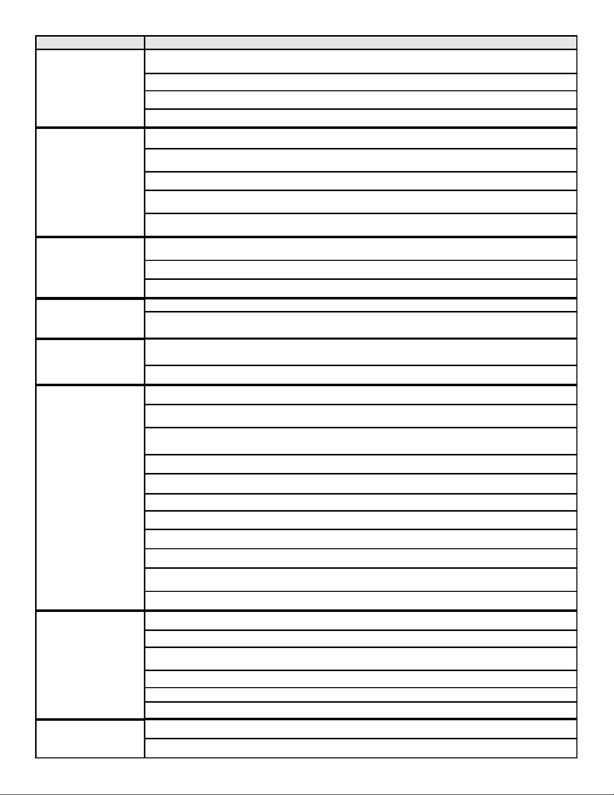
Inspect Maintenance Tasks
Doors, Surrounds
and Fronts
1. Assess condition of screen and replace as necessary. Recommend addition of screen
if one is not present.
2. Inspect for scratches, dents or other damage and repair as necessary.
3. Verify no obstructions to airflow through the louvers.
4. Verify maintenance of proper clearance to combustible household objects.
Gasket Seal, Glass
Assembly and Glass
1. Inspect gasket seal and i ts condition.
2. Inspect glass panels for scratche s and nicks that can lead to breakage when exposed to
heat.
3. Confirm there is no damage to glass or glass frame. Replace as necessary.
4. Verify that latches engage properly, clip studs are not stripped, and glass attachment
components are intact and operating properly. Replace as necessary.
5. Clean glass. Replace glass assembly if severely coated with si licate deposits that cannot
be removed.
Valve Compartment
and Firebox Top
1. Vacuum and wipe out dust, cobwebs, debris or pet hai r. Use caution when cleaning these
areas. Screw tips that have penetrated the sheet metal are sharp and should be avoi ded.
2. Remove any foreign objects.
3. Verify unob structed air circulation.
Logs 1. Inspect for broken, damaged, or missing logs. Replace as necessary.
2. Verify correct log placement and no flame impingement causing sooting. Correct as
necessary.
Firebox
1. Inspect for paint condition, warpage, corrosion or perforation. Sand and repaint as
necessary.
Burner Ignition and
Operation
Venting
Rem ote contr ols
2. Replace appliance if firebox has been perforated.
1. Verify burner is properly secured and aligned wi th pilot or igniter.
2. Clean off burner top, inspect for plugged ports, corrosion or deterioration. Replace burner if
necessary.
3. Replace ember materials with new dime-size and shape pieces. Do not block ports or
obstruct lighting paths.
4. Check for smooth lighting and ignition carryover to all ports. Verify there is no i gnition delay.
5. Inspect for lifting or other flame problems.
6. Verify air shutter is clear of dust and debris.
7. Inspect orifice for soot, dirt or corrosion.
8. Verify manifold and inlet pressures. Adjust regulator as required.
9. Inspect pilot flame strength. Clean or replace orifice as necessary.
10. Inspect thermocouple/thermopile or IP I sensor rod for soot, corrosion and deterioration.
Clean with emery cloth or replace as required.
11. Verify millivolt output. Replace as necessary.
1. Inspect venting for blockage or obstruction such as bird nests, leaves, etc.
2. Confirm that termination cap remains clear and unobstructed by plants, etc.
3. Verify that termination cap clearance to subsequent construction (building additions, decks,
fences or sheds) has been maintained.
4. Inspect for corrosion or separation.
5. Verify weather stripping, sealing and flashing remains intact.
6. Inspect draft shi eld to verify it is not bent, damaged or missing.
1. Verify operation of remote.
2. Replace batteries in remote transmitters and battery-powered receivers.
Heat & Glo • Crescent II • 2083-902 Rev. G • 9/05
43
Page 44

Reference Materials
16
A. Appliance Dimension Diagram
Dimensions are actual appliance dimensions. Use for reference only . For framing dimensions and clearances refer to Section 3.
K
L
M
N
GAS LINE
ACCESS
C
Ø I
J
ELECTRICAL
ACCESS
D
E
O
Figure 16. 1 Appliance Dimensions
B
P
A
Appliance Dimensions Table
Location Inches Millimeter Location Inches Millimeter
A 23-1/4 589 I 8 203
B 20-1/8 511 J 5-3/16 132
C 30-3/4 780 K 4-1/2 113
D 24-5/16 618 L 13-1/2 342
E 1-3/4 43 M 11-1/4 283
F 1 25 N 39-7/8 1013
G 6 152 O 6 152
H 15-1/8 385 P 2-7/8 74
Heat & Glo • Crescent II • 2083-902 Rev. G • 9/0544
F
G
H
Page 45

B. Vent Components Diagrams
Effective
Height/Length
DVP Pipe
(see chart)
Pipe Length/Inches
DVP4 4
DVP6 6
DVP12 12
DVP24 24
DVP36 36
DVP48 48
DVP6A 3 to 6
DVP12A 3 to 12
DVP12MI 3 to 1 2
DVP24MI 3 to 2 4
9-7/8 in.
4-1/4 in.
DVP-FS (Firestop)
10-1/4 in.
DVP45 (45 Elbow)
10 in.
°
45
°
1 in.
14 in.
11-1/4 in.
7-1/4 in.
1-1/4 in.
8-5/8 in.
12-5/8 in.
1/2 in. TYP
DVP90, DVP90ST (90° Elbow)
12 in.
8 in.
6 in.
1 in.
10 in.
UP
5 in.
DVP-HVS (Vent Suppor t) DVP-AS (Attic Shield)
Figure 16.2 DVP vent components
DVP-WS (Wall Shield)
10 in.
1-1/2 in.
12 in.
Heat & Glo • Crescent II • 2083-902 Rev. G • 9/05
24 in.
4 in.
DVP-AD1 (Adapter)
4 in.
DVP-AD2 (Adapter)
5 in.
5 in.
45
Page 46

B. Vent Components Diagrams (continued)
8 in.
15-1/8 in.
Max
Effective
Length
14 in.
Wall Shield
Heat Shield
DVP-TRAP1
Horizontal Termination Cap Kit
DVP-TRAP1
Term Cap
TRAP1 4 -1/8 in. 5-5/8 in.
TRAP2 6-3 /4 in. 10-5/8 i n.
DVP-TRAP SERIES
Horizontal Term Cap
Wall Shield
Horizontal Termination Cap Kit
(Shown with optional extended heat shield)
Minimum
Effective Length Effective Length
HSM
Heat Shield
Maximum
DVP-TRAP2
DVP-TRAP2
Heat Shield
DVP-TRAP1
DVP-TRAPK1
Horizontal Termination Cap Kit
Figure 16.3 DVP vent components
DVP90ST
Wall Shield
Heat & Glo • Crescent II • 2083-902 Rev. G • 9/0546
DVP90ST
HSM
Heat Shield
DVP-TRAP2
Wall Shield
DVP-TRAPK2
Horizontal Termination Cap Kit
Page 47

B. Vent Components Diagrams (continued)
V
13-1/4 in.
24-5/8 in.
27-1/2 in.
31 in.
24-5/8 in.
13-3/4 in.
RF6M
Roof Flashing Multi-pak
13-3/4 in.
BEK
Trap Cap Brick Extension
5 in.
Not for use on this
model.
7-1/4 in.
5-1/4 in.
3-7/8 in.
13-1/4 in.
RF12M
Roof Flashing Multi-pak
12-1/2 in.
DVP-TVHW
Ve rtical Termination Cap
(High wind)
10-1/2 in.
DVP-TV
ertical Termination Cap
DVP Components
13-7/8 in.
14 in.
Figure 16. 4 DVP vent components
9-1/2 in.
DRC-RADIUS
Cap Shield
11-5/8 in.
7-1/8 in.
5-3/4 in.
Heat & Glo • Crescent II • 2083-902 Rev. G • 9/05
12-1/8 in.
COOL-ADD
Cap Shield
47
Page 48

C. Service Parts List
CRESCENT II
(NG, LP) Exploded Parts Diagram
16
9
87
17
Beginning Manufacturing Date: 4-05
Ending Manufacturing Date: ______
12
13
10
20
3
4
19
6
18
11
2
5
14 Log Set Assembly with burner
1
Part number list on following page.
15
Heat & Glo • Crescent II • 2083-902 Rev. G • 9/0548
Page 49

C. Service Parts List
CRESCENT II
IMPORT ANT: THIS IS DA TED INFORMATION. The most current information is located on your dealers VIP site. When order-
ing, supply serial and model numbers to ensure correct service parts.
ITEM DESCRIPTION SERIAL # PART NUMBER
1Valve NG 750-500
1 Valve LP 593-501
2 Glass Do or Asse mbly GLA-CRESCENTII
3 C ontrol Module 593-592
4 3V A daptor Plug 593-593a
5 Regulato r As sem bly NG 2083-062
5 Regulator Assembly LP 2083-063
6 Circuit Board 2083-030
7Pilot Assembly NG 2090-012
7 Pilot Assembly LP 2090-013
8 Glass, Light Box SRV2083-135
9 Orange Film (Kapton) 2083-180
10 Junction B ox 4021-013
11 4 Lead Wall Switch Wire 2083-031
12 Nailing Tab 2083-212
13 12V Adaptor 2083-022
14 Log Set Assembly with Burner LOGS-CRESCENTII
15 Log #4 SRV2083-185
16 Bracket, Glass 2083-134
17 Gasket, Light Box 2083-132
18 Valve Bracket 2083 -133
19 Flex Tube 2073-007
20 Light Bulb See note
Hood 2083-208
Glass Latch 386-122A
Wire Assembly 593-590A
Flue Restrictor 2083-206
Solenoid - 110 Volt Hi/Lo (NG only) HTI-17-006
Lava Rock Bag (1 lb.) 705-420
Tec o -S i l 2083-790
Wall Switch and Cover Plate 4041-128
Burner Orifice NG (#52C) 582-852
Burner Orifice LP (#61C) 582-861
ACCESSORIES
NG Conversion - IPI NGK-CRESCENTII
LP Conversion - IPI LPK-CRESCENTII
Patch Kit SRV-PACK
Remote Contro l Kit RC-SMART-HNG
Remote Contro l Kit SMART-STAT-HNG
Note: Replacement bulbs to be supplied by homeowner . Recommended replacement: Sylvania mini candelabra 75 watts.
Heat & Glo • Crescent II • 2083-902 Rev. G • 9/05
49
Page 50

D. Limited Lifetime Warranty
LIMITED LIFETIME WARRANTY
HEAT & GLO GAS APPLIANCE PRODUCTS
BASIC ONE-YEAR WARRANTY. HEAT & GLO, a brand of HEARTH & HOME TECHNOLOGIES INC., located at 20802 Kensington
Boulevard, Lakeville, MN 55044, (“HEAT & GLO”) warrants to the original owner that your new HEA T & GLO Gas Appliance (the “Product”)
will be free from defects in materials and workmanship for a period of one year from the date of installation. During the first year, HEA T & GLO
will replace or repair, at its discretion, any defective components at its sole cost and expense, including payment of all reasonable labor costs
incurred in replacing or repairing such components. This basic warranty is subject to the conditions, exclusions and limitations described below.
EXTENDED LIFETIME COVERAGE. HEAT & GLO warrants that the firebox, heat exchanger, log(s), and burner will not be defective in
material or workmanship during the period the Product is owned by the original owner, subject to the following conditions, exclusions and
limitations described below.
CONDITIONS, EXCLUSIONS AND LIMIT ATIONS:
1. This warranty applies to the original owner only and is nontransferable.
2. This warranty applies only to Products installed in the United States of America or Canada.
3. This warranty is limited to the replacement or repair of defective components or workmanship and HEAT & GLO may fully discharge all
obligations under this warranty by repairing or replacing, at its discretion, the defective components. The maximum amount recoverable
under this warranty is limited to the purchase price of the Product and, if HEAT & GLO is unable to provide replacement or repair in an
expedient and cost-effective manner, HEA T & GLO may discharge all obligations under this warranty by refunding the purchase price of
the Product. IN NO EVENT SHALL HEA T & GLO BE LIABLE FOR ANY INCIDENT AL OR CONSEQUENTIAL DAMAGES CAUSED BY
DEFECTS IN THE PRODUCT.
4. Any labor and related repair charges relating to the costs and expenses of replacing or repairing defective components under the Limited
Lifetime Warranty are not covered by this warranty , except as provided for under the Basic One-Y ear W arranty .
5. Components and parts made by other manufacturers, whether sold with the Product or added thereafter, are NOT covered by this
warranty unless expressly authorized and approved by HEAT & GLO in writing.
6. Any damages caused by environmental conditions, inadequate ventilation or drafting caused by tight sealing construction of the structure,
air handling devices such as exhaust fans or forced air furnaces, or other such causes are not covered by this warranty.
7. This warranty will be void if:
a) The Product is not installed, operated and maintained in compliance with local building codes and with the instructions in the Installer’s
Guide, Owner’s Guide and Listing Agent Identification Label furnished with the Product.
b) Any parts or components made by other manufacturers are added or used in the Product, unless expressly authorized and
approved by HEAT & GLO in writing.
c) Any service work is performed on the Product by anyone other than an authorized HEAT & GLO representative.
d) The Product is damaged due to shipping, improper handling, accident, abuse or misuse.
e) Fuels other than those specified in the Installer’s Guide and Owner’s Guide are used.
f)
Modification was made to the Product which was not expressly authorized and approved by HEAT & GLO in writing.
EXCEPT TO THE EXTENT PROVIDED BY LA W, HEA T & GLO MAKES NO EXPRESS W ARRANTIES OTHER THAN THE W ARRANTY
SPECIFIED HEREIN. THE DURATION OF ANY IMPLIED WARRANTY IS LIMITED T O THE DURATION OF THE WARRANTY SPECIFIED ABOVE.
Some states do not allow limitations on how long an implied warranty lasts, or do not allow exclusion or limitation of incidental or consequential
damages, so those limitations may not apply to you. This warranty gives you specific legal rights, and you may also have other rights which vary
from State to State.
If warranty service is needed you should contact your installing dealer and if the installing dealer is unable to provide necessary parts or
components, contact the nearest authorized HEAT & GLO dealer or supplier.
NOTES TO CUSTOMER:
1. In order to insure proper installation, operation and maintenance HEAT & GLO strongly recommends annual
servicing by an authorized HEA T & GLO dealer .
2. Please complete this information and retain this warranty in a safe place for future reference: Installation Date:______
Model #:_________________ Serial #:______________ Installing Contractor:_________________________
3. HEA T & GLO reserves the right to make changes at any time, without notice, in design, material, specifications
and prices of the Product. HEA T & GLO also reserves the right to discontinue styles and product s.
© 2005 Hearth & Home Technologies Inc.
060-981C 1/05
Heat & Glo • Crescent II • 2083-902 Rev. G • 9/0550
Page 51

E. Contact Information
Heat & Glo, a brand of Hearth & Home Technologies Inc.
20802 Kensington Boulevard, Lakeville, MN 55044
www.fireplaces.com
Please contact your Heat & Glo dealer with any questions or concerns.
For the number of your nearest Heat & Glo dealer,
please call 1-888-427-3973.
- NOTES -
_______________________________________________________________________________
_______________________________________________________________________________
_______________________________________________________________________________
_______________________________________________________________________________
_______________________________________________________________________________
_______________________________________________________________________________
_______________________________________________________________________________
_______________________________________________________________________________
_______________________________________________________________________________
CAUTION
DO NOT DISCARD THIS MANUAL
Important operating and
•
maintenance instructions included.
Read, understand and
•
follow these instructions
for safe installation and
operation.
Leave this manual with party
•
responsible for use and operation.
This product may be covered by one or more of the following patents: (United St ates) 4593510, 4686807, 4766876, 4793322, 4811534, 5000162, 5016609, 5076254, 51 13843, 5191877, 5218953, 5263471, 5328356, 5341794,
5347983, 5429495, 5452708, 5542407, 5601073, 5613487, 5647340, 5688568, 5762062, 5775408, 5890485, 5931661, 5941237, 5947112, 5996575, 6006743, 6019099, 6048195, 6053165, 6145502, 6170481, 6237588, 6296474,
Î
6374822, 6413079, 6439226, 6484712, 6543698, 6550687, 6601579, 6672860, 6688302B2, 6715724B2, 6729551, 6736133, 6748940, 6748942, 6769426, 6774802, 6796302, 6840261, 6848441, 6863064, 6866205, 6869278,
6875012, 6880275, 6908039, 6919884, D320652, D445174, D462436; (Canada) 1297749, 2195264, 2225408, 2313972; (Australia) 780250, 780403, 1418504 or other U.S. and foreign patents pending.
Printed in U.S.A. - Copyright 2005
Heat & Glo • Crescent II • 2083-902 Rev. G • 9/05
51
 Loading...