

Page 1
Model:
CFX-Crescent
Owner’s Manual
Installation and Operation
CAUTION
DO NOT DISCARD THIS MANUAL
Important operating
•
and maintenance
instructions included.
WARNING: If the information in these
instructions is not followed exactly , a fire
or explosion may result causing property damage, personal injury , or death.
• Do not store or use gasoline or other flammable vapors and liquids in the vicinity of this or
any other appliance.
• What to do if you smell gas
- Do not try to light any appliance
- Do not touch any electrical switch. Do not
use any phone in your building.
- Immediately call your gas supplier from a
neighbor’s phone. Follow the gas supplier’s
instructions.
- If you cannot reach your gas supplier, call
the fire department.
• Installation and service must be performed by
a qualified installer , service agency , or the gas
supplier .
This appliance may be installed as an OEM installation in
manufactured home (USA only) or mobile home and must
be installed in accordance with the manufacturer’s instructions and the manufactured home construction and safety
standard, Title 24 CFR, Part 3280 or Standard for Installa-
tion in Mobile Homes, CAN/CSA Z240MH.
This appliance is only for use with the type(s) of gas indi-
cated on the rating plate.
Read, understand and follow
••
these instructions for safe
installation and operation.
DO NODO NO
DO NO
DO NODO NO
DISCARDDISCARD
DISCARD
DISCARDDISCARD
TT
T
Leave this manual with
party responsible for
use and operation.
TT
W ARNING
HOT SURFACES!
Glass and other surfaces are hot during
operation AND cool down.
Hot glass will cause burns.
• DO NOT touch glass until it is cooled
• NEVER allow children to touch glass
• Keep children away
• CAREFULL Y SUPERVISE children in same room as fireplace.
• Alert children and adults to hazards of high temperatures.
High temperatures may ignite clothing or other flammable
materials.
• Keep clothing, furniture, draperies and other flammable
materials away.
This appliance has been supplied with an integral barrier
to prevent direct contact with the fixed glass panel. DO
NOT operate the appliance with the barrier removed.
Contact your dealer or Hearth & Home Technologies if the
barrier is not present or help is needed to properly install one.
In the Commonwealth of Massachusetts installation must
be performed by a licensed plumber or gas fitter.
See Table of Contents for location of additional
Commonwealth of Massachusetts requirements.
Installation and service of this appliance should be
performed by qualified personnel. Hearth & Home
T echnologies suggests NFI certified or factory-trained
professionals, or technicians supervised by an NFI
certified professional.
Í
Heat & Glo • CFX-CRESCENT • 705-900 Rev . P • 12/07
1
Page 2

SAFETY AND WARNING INFORMATION
READ and UNDERSTAND all instructions carefully before starting the installation.
!
FAILURE TO FOLLOW these installation instructions may result in a possible fire
hazard and will void the warranty.
Prior to the first firing of the fireplace, READ the Using Your Fireplace section of the
!
Owners Guide.
DO NOT USE this appliance if any part has been under water. Immediately CALL a
!
qualified service technician to inspect the unit and to replace any part of the control
system and any gas control which has been under water.
THIS UNIT IS NOT FOR USE WITH SOLID FUEL.
!
Installation and repair should be PERFORMED by a qualified service person. The
appliance and venting system should be INSPECTED before initial use and at least
!
annually by a professional service person. More frequent cleaning may be required
due to excessive lint from carpeting, bedding material, etc. It is IMPERATIVE that the
unit’s control compartment, burners, and circulating air passageways BE KEPT
CLEAN to provide for adequate combustion and ventilation air.
Always KEEP the appliance clear and free from combustible materials, gasoline, and
!
other flammable vapors and liquids.
NEVER OBSTRUCT the flow of combustion and ventilation air. Keep the front of the
!
appliance CLEAR of all obstacles and materials for servicing and proper operations.
Due to the high temperature, the appliance should be LOCATED out of traffic areas
!
and away from furniture and draperies. Clothing or flammable material SHOULD NOT
BE PLACED on or near the appliance.
Children and adults should be ALERTED to the hazards of high surface temperature
!
and should STAY A WAY to avoid burns or clothing ignition. Young children should be
CAREFULL Y SUPERVISED when they are in the same room as the appliance.
These units MUST use one of the vent systems described in the Installing the Fireplace
!
section of the Installers Guide. NO OTHER vent systems or components MAY BE USED.
This gas fireplace and vent assembly MUST be vented directly to the outside and
!
MUST NEVER be attached to a chimney serving a separate solid fuel burning
appliance. Each gas appliance MUST USE a separate vent system. Common vent
systems are PROHIBITED.
INSPECT the external vent cap on a regular basis to make sure that no debris is
!
interfering with the air flow.
The glass door assembly MUST be in place and sealed, and the trim door assembly
!
MUST be in place on the fireplace before the unit can be placed into safe operation.
DO NOT OPERATE this appliance with the glass door removed, cracked, or broken.
!
Replacement of the glass door should be performed by a licensed or qualified service
person. DO NOT strike or slam the glass door.
The glass door assembly SHALL ONLY be replaced as a complete unit, as supplied
!
by the gas fireplace manufacturer. NO SUBSTITUTE material may be used.
DO NOT USE abrasive cleaners on the glass door assembly. DO NOT ATTEMPT to
!
clean the glass door when it is hot.
Turn off the gas before servicing this appliance. It is recommended that a qualified
!
service technician perform an appliance check-up at the beginning of each heating
season.
Any safety screen or guard removed for servicing must be replaced before operating
!
this appliance.
DO NOT place furniture or any other combustible household objects within 36 inches of
!
the fireplace front.
Heat & Glo • CFX-CRESCENT • 705-900 Rev . P • 12/072
Page 3

Safety and Warning Information ..............................2
Service Parts List ..................................................... 4
Section 1: Approvals and Codes ........................... 6
Appliance Certification ...........................................6
Installation Codes..................................................6
High Altitude Installations......................................6
Commonwealth of Massachusetts Requirements . 7
Section 2: Getting Started ......................................8
Introducing the Heat & Glo Gas Fireplaces.............8
Pre-installation Preparation ...................................8
Section 3: Installing the Fireplace ...................... 10
Step 1 Locating the Fireplace ............................10
Step 2 Framing the Fireplace ............................ 11
Step 3 Installing the Vent System ......................12
A. Vent System Approvals ......................12
B. Installing V ent Components................ 16
C. Vent Termination................................ 21
Step 4 Positioning, Leveling, and
Securing the Fireplace ........................... 26
Step 5 The Gas Control Systems .. ................... 26
Step 6 The Gas Supply Line.............................. 27
Step 7 Gas Pressure Requirements . .... ... .........28
Step 8 Wiring the Fireplace...............................29
Step 9 Finishing ................................................31
Step 10
Removing Glass Door, Installing Trim,
Logs and Ember Material .....................32
Removing Glass Door ........................... 32
Installing Door Handles ..........................32
Positioning the Logs...............................33
Shutter Settings .....................................33
Placing the Ember Material
and Lava Rocks.....................................33
Step 11
Step 12
Before Lighting the Fireplace ..................34
Lighting the Fireplace .............................34
After the Installation .............................................34
Í
Table of
Contents
Section 4: Maintaining and Servicing
Your Fireplace ..................................... 35
Contact Information ............................................. 38
Î = Contains updated information.
Heat & Glo • CFX-CRESCENT • 705-900 Rev . P • 12/07
Í
3
Page 4
6
4
3
5
1
2
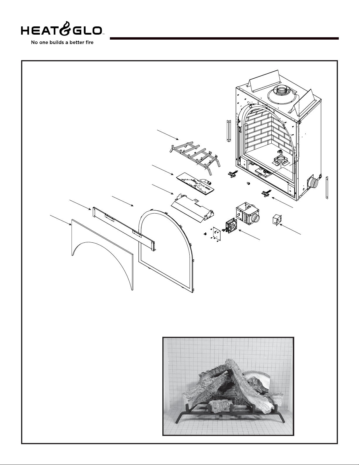
Service Parts
7
8
9
10
11
12
13
14
15
CFX-Crescent
Service Parts Diagram
Beginning Manufacturing Date: June 2000
Ending Manufacturing Date: ______
Part number list on following page.
Log Set Assembly
16
Heat & Glo • CFX-CRESCENT • 705-900 Rev . P • 12/074
Page 5
Service Parts List
IMPORTANT : THIS IS DATED INFORMATION. When requesting service or replacement
Î
parts for your appliance please provide model number and serial number. All parts listed
in thi s m anual m ay be ordered from an authorized deal er.
ITEM DESCRIPTION SERIAL # PART NUMBER
Log Set A ssembly LOGS-CRESCENT
1
2
3
4
5
6
7
8
9 Fresh Air Diffuser
10
11
12
13
14 Junct ion Box
15
Additional service part numbers appear on f ol lowing page.
Log 1 SRV705-701
Log 2 SRV705-703
Log 3 SRV705-702
Log 4 SRV705-704
Log 5 SRV705-705
Log 6 SRV593-704
Grate Assembly 705-360A
Burner NG
Burner LP
Glass Door Assembly GLA -CRESCENT
Insulat ion Suppor t 705-260
Insulat ion Board 705-403
Combustion B lo wer 705-567A
Glass Attachment Assembly - Bottom (qty. 2) 386-122A
Glass Clip Assembly - T op (qty . 2) SRV705-206A
Or ific e N G (#36 A) Pre 002182 991
Or ific e N G (#35 A) Post 0021829 91
Or ific e LP (#51A)
Finishing St r i ps (qty. 2) 705-233
Limit Switc h 514-530
Mineral Wool 050-721
Lava Roc k 705-420
Patch Kit SRV-PATCH-CFX
D S I CON V ERSIO N KI T S ( P re 00218299 1)
Conv ersion Kit NG NGK-CRESCENT
Conv ersion Kit LP LPK-CRESCENT
IPI CON V ERS ION KITS ( P ost 2182991)
Conver sion Kit NG
Conver sion Kit LP
Pilot Or if ic e NG
Pilot Or if ic e LP
Regulator NG
Regulator LP
Pre 002182 991 705-326A
Post 0021829 91 705-328A
Pre 002182 991 705-325A
Post 0021829 91 7035-327A
Pre 002182 991
Post 0021829 91
Pre 002182 991 100-256A
Post 0021829 91
N/A N
705-262 N
705-250A Y
079-831 Y
065-800 Y
079-803 Y
N/A
LPK-CRESCENTIPI
446-505
446-517
NGK-DXF
LPK-DXF
CFX-Crescent
Stocked
at Depot
Y
N
N
N
N
N
N
N
Y
Y
Y
Y
Y
N
N
N
Y
Y
Y
N
Y
N
N
N
Y
Y
Y
Y
Y
Y
Y
Y
Heat & Glo • CFX-CRESCENT • 705-900 Rev . P • 12/07
5
Page 6
Service Parts
1
2
3
6
5
4
CFX-Crescent
Î
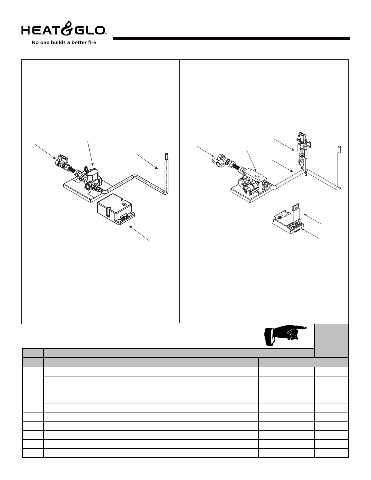
Pre 002182991 Valve Assembly
3
4
Valve Assembly Diagram/Part s List
Post 002182991 Valve Assembly
2
Beginning Manufacturing Date: June 2000
Ending Manufacturing Date: ______
5
IMPORTANT THIS IS DATED INFORMATI ON: When Requesting service or replacement
parts for your appliance please provide model number and serial number. All parts listed
in thi s m anual m ay be ordered from an authorized dealer.
ITEM DESCRIPTION
Pre 002182991 Po st 002182991
1
2 Burner Tube
3
4 Flex B al l V al ve Ass em bly 492-320A 492-320A Y
5 Module 501-592 593-592 Y
6 Module W ire A ss em bl y N/A 593-590A Y
Pilot Assembly NG
Pilot Assembly LP
Valve NG 476-500 593-500 Y
Valve LP 476-500 593-501 Y
Ignitor 501-591 N/A Y
3 Volt Transformer N/A 593-593A Y
N/A 385-510 A Y
N/A 385-511 A Y
570-302A 570-302A Y
PART NUM BER
Stocked
at Depot
Heat & Glo • CFX-CRESCENT • 705-900 Rev . P • 12/076
Page 7
1
Approvals
and Codes
Approval Listings
and Codes
MODEL LABORA TORY TYPE STANDARD
CFX-Crescent Underwriters Direct Vent ANSI
Laboratories Gas Fireplace
Installation Codes
The fireplace installation must conform to local codes. Before installing the
fireplace, consult the local building code agency to ensure that you are in
compliance with all applicable codes, including permits and inspections.
In the absence of local codes, the fireplace installation must conform to the
National Fuel Gas Code ANSI Z223.1 (in the United S tates) or the CAN/CGAB149 Installation Codes (in Canada). The appliance must be electrically
grounded in accordance with local codes or, in the absence of local codes with
the National Electric Code ANSI/NFPA No. 70 (in the United St ates), or to the
CSA C22.1 Canadian Electric Code (in Canada).
Appliance Certification
The Heat & Glo fireplace models discussed in this
Installers Guide have been tested to certification
standards and listed by the applicable laboratories.
CERTIFICATION
Z21.50-2000•CSA2.22-M98
This model may be installed in a bedroom or bed-sitting room in the U.S.A. and
Canada.
High Altitude Installations
U.L. Listed gas appliances are tested and approved without requiring changes for
elevations from 0 to 2,000 feet in the U. S. A. and in Canada.
When installing this appliance at an elevation above 2,000 feet, it may be necessary
to decrease the input rating by changing the existing burner orifice to a smaller
size. Input rate should be reduced by 4% for each 1000 feet above a 2000 foot
elevation in the U.S.A. or 10% for elevations between 2000 and 4500 feet in Canada.
If the heating value of the gas has been reduced, these rules do not apply. To
identify the proper orifice size, check with the local gas utility .
If installing this appliance at an elevation above 4,500 feet (in Canada), check with
local authorities.
Heat & Glo Quality Systems
registered by SGS ICS
Heat & Glo • CFX-CRESCENT • 705-900 Rev. P • 12/077
Page 8

NOTE: The following requirements reference various
Massachusetts and national codes not contained in
this document.
Requirements for the Commonwealth of
Massachusetts
For all side wall horizontally vented gas fueled equipment
installed in every dwelling, building or structure used in whole
or in part for residential purposes, including those owned or
operated by the Commonwealth and where the side wall
exhaust vent termination is less than seven (7) feet above
finished grade in the area of the venting, including but not
limited to decks and porches, the following requirements
shall be satisfied:
Installation of Carbon Monoxide Detectors
At the time of installation of the side wall horizontal vented
gas fueled equipment, the installing plumber or gasfitter shall
observe that a hard wired carbon monoxide detector with an
alarm and battery back-up is installed on the floor level where
the gas equipment is to be installed. In addition, the installing plumber or gasfitter shall observe that a battery operated or hard wired carbon monoxide detector with an alarm is
installed on each additional level of the dwelling, building or
structure served by the side wall horizontal vented gas fueled equipment. It shall be the responsibility of the property
owner to secure the services of qualified licensed professionals for the installation of hard wired carbon monoxide
detectors.
In the event that the side wall horizontally vented gas fueled
equipment is installed in a crawl space or an attic, the hard
wired carbon monoxide detector with alarm and battery backup may be installed on the next adjacent floor level.
In the event that the requirements of this subdivision can
not be met at the time of completion of installation, the
owner shall have a period of thirty (30) days to comply with
the above requirements; provided, however , that during said
thirty (30) day period, a battery operated carbon monoxide
detector with an alarm shall be installed.
Approved Carbon Monoxide Detectors
Each carbon monoxide detector as required in accordance
with the above provisions shall comply with NFP A 720 and
be ANSI/UL 2034 listed and IAS certified.
Signage
A metal or plastic identification plate shall be permanently
mounted to the exterior of the building at a minimum height
of eight (8) feet above grade directly in line with the exhaust
vent terminal for the horizontally vented gas fueled heating
appliance or equipment. The sign shall read, in print size no
less than one-half (1/2) inch in size, “GAS VENT DIRECT-
L Y BELOW . KEEP CLEAR OF ALL OBSTRUCTIONS”.
Inspection
The state or local gas inspector of the side wall horizontally
vented gas fueled equipment shall not approve the installation unless, upon inspection, the inspector observes carbon
monoxide detectors and signage installed in accordance with
the provisions of 248 CMR 5.08(2)(a)1 through 4.
Exemptions
The following equipment is exempt from 248 CMR 5.08(2)(a)1
through 4:
• The equipment listed in Chapter 10 entitled “Equipment
Not Required T o Be V ented” in the most current edition
of NFPA 54 as adopted by the Board; and
• Product Approved side wall horizontally vented gas fueled equipment installed in a room or structure separate
from the dwelling, building or structure used in whole or
in part for residential purposes.
MANUFACTURER REQUIREMENTS
Gas Equipment Venting System Provided
When the manufacturer of Product Approved side wall horizontally vented gas equipment provides a venting system
design or venting system components with the equipment,
the instructions provided by the manufacturer for installation of the equipment and the venting system shall include:
• Detailed instructions for the installation of the venting
system design or the venting system components; and
• A complete parts list for the venting system design or
venting system.
Gas Equipment Venting System NOT Provided
When the manufacturer of a Product Approved side wall
horizontally vented gas fueled equipment does not provide
the parts for venting the flue gases, but identifies “special
venting systems”, the following requirements shall be satisfied by the manufacturer:
• The referenced “special venting system” instructions shall
be included with the appliance or equipment installation
instructions; and
• The “special venting systems” shall be Product Approved
by the Board, and the instructions for that system shall
include a parts list and detailed installation instructions.
A copy of all installation instructions for all Product Approved side wall horizontally vented gas fueled equipment,
all venting instructions, all parts lists for venting instructions, and/or all venting design instructions shall remain
with the appliance or equipment at the completion of the
installation.
See Gas Connection section for additional Commonwealth of Massachusetts requirements.
Heat & Glo • CFX-CRESCENT • 705-900 Rev . P • 12/078
Page 9
Introducing the
Heat & Glo
Gas Fireplaces
Heat & Glo direct vent gas fireplaces are designed to
operate with all combustion air siphoned from
outside of the building and all exhaust gases
expelled to the outside.
The information contained in this Installers Guide,
unless noted otherwise, applies to all models and
gas control systems.
2
Pre-installation
Preparation
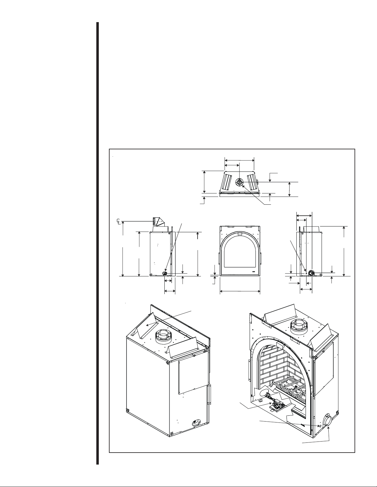
Gas fireplace diagrams, including the dimensions,
are shown in this section.
This gas fireplace and its components are tested
and safe when installed in accordance with this
Installers Guide. Report to your dealer any parts
damaged in shipment, particularly the condition of
the glass. Do not install any unit with damaged,
incomplete, or substitute parts.
The vent system components and trim doors are
shipped in separate packages. The gas logs are
packaged separately and must be field installed.
Read all of the instructions before starting the
installation. Follow these instructions carefully
during the installation to ensure maximum
safety and benefit. Failure to follow these
instructions will void the owner’s warranty and
may present a fire hazard.
This model MUST use SL-Series Direct Vent
Components and T ermination Kit s (as indicated in this
guide) for exhausting flue gases AND model AK-CFX
Air Kit for combustion air. NOTE: 4-inch insulated
ducting is required. See venting section for details.
Getting
St arted
The Heat & Glo Warranty will be voided by , and Heat
& Glo disclaims any responsibility for, the following
actions:
• Installation of any damaged fireplace or vent
system component.
• Modification of the fireplace or direct vent system.
• Installation other than as instructed by Heat & Glo.
• Improper positioning of the gas logs or the glass
door.
• Installation and/or use of any component part not
manufactured and approved by Heat & Glo, not
withstanding any independent testing laboratory or
other party approval of such component part or
accessory.
ANY SUCH ACTION MAY POSSIBLY CAUSE A
FIRE HAZARD.
Heat & Glo • CFX-CRESCENT • 705-900 Rev . P • 12/07
9
Page 10
When planning a fireplace installation, it’s necessary to determine:
• Where the unit is to be installed.
• The vent system configuration to be used.
• Gas supply piping.
• Electrical wiring.
• Framing and finishing details. Refer to Finishing V ariations addendum included
in manual bag.
• Whether optional accessories, such as a remote control, arch surround or door
front are desired.
If the fireplace is to be installed on carpeting or tile, or on any combustible
material other than wood flooring, the fireplace should be installed on a metal or
wood panel that extends the full width and depth of the fireplace.
46 3/4
(1187mm)
38 1/2
(978mm)
6 (153mm)
12 3/4 (323mm)
19 1/8 (487mm)
3 (76mm)
GAS LINE
ACCESS
38 1/4
(972mm)
2 3/8
(61mm)
9 (231mm)
TOP VENT
COLLARS
1 1/8
(29mm)
34 1/2 (876mm)
25 3/8 (645mm)
9 1/2 (241mm)
ØØ
6 5/8 (168mm)
8 1/2 (216mm)
ELECTRICAL
ACCESS
2 3/8 (62mm)
5 1/2
(138mm)
12 5/8 (319mm)
12 7/8 (326mm)
9 3/4 (248mm)
2 3/4
(68mm)
43 1/8 (2)
(1096mm)
CONTROL
VALVE
ELECTRICAL
ACCESS
Figure 1. Diagram of the CFX-CRESCENT
Heat & Glo • CFX-CRESCENT • 705-900 Rev . P • 12/0710
AK-CFX
STARTING
COLLAR
Page 11
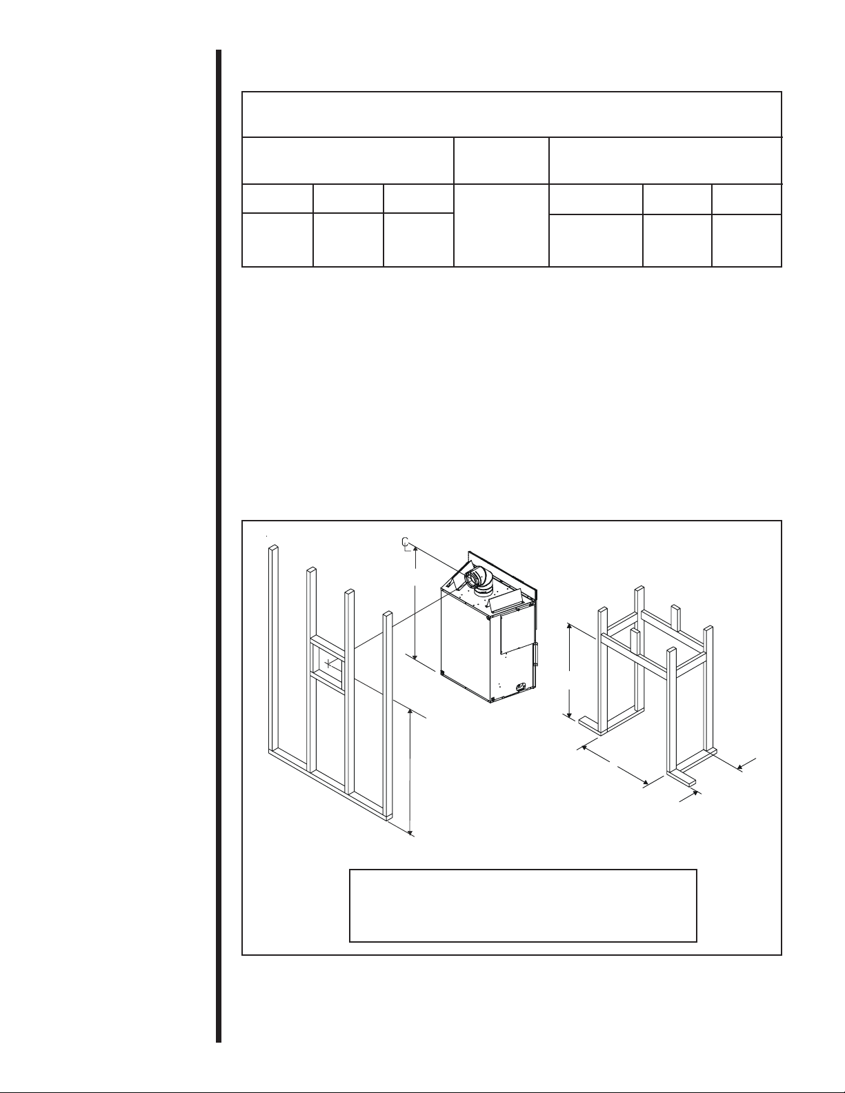
Step 1
Locating the
fireplace
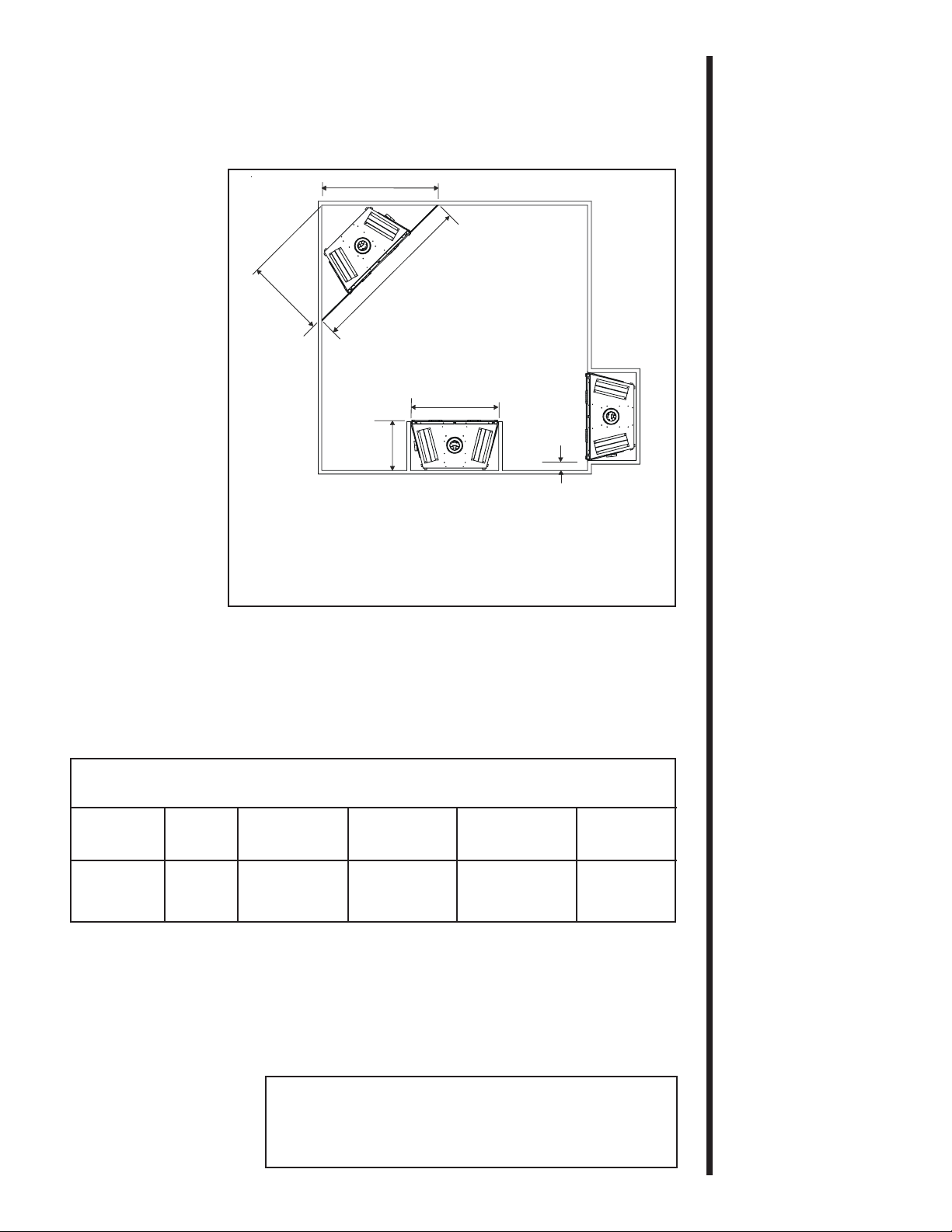
The diagram below shows space and clearance
requirements for locating a fireplace within a room.
C
3
A
B
Installing the
Fireplace
E
D
AB CDE
66 5/8 33 1/4 47 1/8 19 5/8 35 1/2
NOTE: Dimensions shown in inches.
Figure 2. Fireplace Dimensions, Locations, and
Space Requirements
Clearance Requirements
The top, back, and sides of the fireplace are defined
by stand-offs.
Minimum Clearances from the Fireplace to
Combustible Materials
Glass Rear Sides of Top of
Front Floor of Fireplace Fireplace Fireplace* Ceiling*
36 inches 0 1/2 inch 1/2 inch 14 1/2 inches** 18 inches
(914mm) (13mm) (13mm) (368mm) (457mm)
I INCH
* NOTE: Add 1 3/8” to these measurements if measuring from the top of the door .
** NOTE: 2 x 4 framing only allowed at 43 5/8” (see Figures 3 and 26).
The minimum clearance to a perpendicular wall extending past the face of the fireplace is one inch (25mm).
The back of the fireplace may be recessed 19 1/4
inches (489mm) into combustible construction.
The distance from the unit to combustible construction is
to be measured from the unit outer wrap surface to the
combustible construction, NOT from the screw heads that
secure the unit together.
Heat & Glo • CFX-CRESCENT • 705-900 Rev . P • 12/07
11
Page 12
Minimum Clearances from the Vent Pipe to
Combustible Materials
For Vertical
For Horizontal Sections Sections At Wall Firestop s
Top Bottom Sides Top Bottom Sides
3 inches 1 inch 1 inch 1 inch 2-1/2 inches 1/2 inch 1 inch
(75 mm) (25 mm) (25 mm) (25 mm) (63.7 mm) (13 mm) (25 mm)
For minimum clearances, see the direct vent
termination clearance diagrams on pages 21 and
22 in this section.
Step 2
Framing the
Fireplace
CAUTION
Fireplace framing can be built before or after the
fireplace is set in place. Framing should be
positioned to accommodate wall coverings and
fireplace facing material. The diagram below shows
framing reference dimensions.
MEASURE FIREPLACE DIMENSIONS AND
VERIFY FRAMING METHODS AND WALL
COVERING DETAILS BEFORE FRAMING
CONSTRUCTION BEGINS.
Framing should be
constructed of 2 X 4
46 3/4 (REF)
B
lumber or heavier.
D
A B C D
35 1/2” 43 5/8” 19 5/8” 47 3/4”
(902mm) (1108mm) (498mm) (1213mm)
Figure 3. Framing Dimensions
Heat & Glo • CFX-CRESCENT • 705-900 Rev . P • 12/0712
Shows center of
10” x 10” vent
framing holes
for top venting.
A
C
Page 13

Step 3
Installing the
Vent System
A. Vent System Approvals
This model is approved to use SL-series direct vent pipe components and terminations (as indicated in this guide), and model AK-CFX air kits. Approved vent system components are labeled for identification. This pipe is tested and listed as an approved component of the fireplace. The pipe is tested to be run
inside an enclosed wall. There is NO requirement for inspection
openings at each joint within the wall. There is no required pitch
for horizontal vent runs. This model is not approved for use
with SLK-01D termination cap. NO OTHER VENTING SYSTEMS OR COMPONENTS MAY BE USED.
Detailed
tion kit and should be used in conjunction with this Installers Guide.
Drawing below shows vent system components and terminations.
Vent System Component s
Vent System
T ermination Kits
SLK-991DA
SLK-01TRD
installation instructions are included with each vent termina-
VERTICAL
TERMINATION
HORIZONTAL
TERMINATION
WALL FIRESTO P
90 DEGREE
ELBOW
NOTE: SLK-01D is NOT
approved for use.
CEILING
FIRESTOP
STORM COLLAR
ROOF FLASHING
HORIZONTAL PIPE
SUPPORT
PIPE LENGTH
WALL BRACKET
COMBUSTION
AIR DUCT COLLAR
Figure 4. Vent Components and Terminations
Identifying Vent Components
The vent systems installed on this gas fireplace may include up to eight 90°
elbow
assemblies. The relationships of vertical rise to horizontal run in vent configurations
using 90° elbows MUST BE strictly adhered to. The rise to run relationships are shown
in the venting drawings and tables. Refer to the diagrams on the next several pages.
NOTE: TWO 45° ELBOWS MAY BE USED IN PLACE OF ONE 90° ELBOW.
RISE TO RUN RATIOS IN THE VENT SYSTEM MUST BE FOLLOWED IF 45°
ELBOWS ARE USED.
WARNING: THIS UNIT IS DESIGNED T O OPERA TE USING OUTSIDE COM-
!
BUSTION AIR. IT IS MANDA T ORY T O INST ALL AN AK-CFX AIR KIT USING
4-INCH INSULA TED DUCTING. THE 4-INCH (102MM) DUCT COLLAR FOR
THE AIR KIT WILL COME MOUNTED T O THE FIREPLACE. SEE FIGURE 6.
NOTE: When installing the AK-CFX outside air kit, it is normally not necessary
to install the air intake cap on the same wall as the exhaust termination cap.
However, installations involving t all buildings or areas subjected to frequent high
winds, it is recommended that the air intake cap be installed on the same wall
as the exhaust termination cap.
Heat & Glo • CFX-CRESCENT • 705-900 Rev . P • 12/07
13
Page 14

17-24
9 1/4
6 5/8
SL-45D
SL-17/24D
(SL17-24D)
6 1/2
11 3/4
6 3/8
6 5/8
5 3/4
6 3/8
SL-06DSL-12D
SL-90D
6 1/2
6 5/8
6 1/2
9 5/8
9 5/8
35 3/4
23 3/4
12-17
8 3/4
SL-09D
SL-12/17D (SL12-17D)
SL-24D
SL-36D
Note: Pipes overlap 1 3/8 inches (34.93mm) at each joint.
Figure 5. SL-Series Direct Vent Component Specifications
(4-inch inner pipe/6 5/8-inch outer pipe)
47 3/4
SL-48D
Heat & Glo • CFX-CRESCENT • 705-900 Rev . P • 12/0714
Page 15

COMBUSTION
DUCT COLLAR
FOR
AK-CFX AIR KIT
Figure 6. Unit with duct collar .
The combustion air duct on the right side of the unit can run
horizontally or elbow upward 46 feet long. This duct can
elbow down to a maximum of 18 feet.
CAP
STRAIGHT UP
VERTICAL VENTING
V (FT.)
46' MAX. (14M)
V
Figure 7. Straight Up Vertical Venting
Heat & Glo • CFX-CRESCENT • 705-900 Rev . P • 12/07
15
Page 16

Total H (Horizontal run) = 50 feet maximum.
Total V (Vertical run) = 46 feet maximum.
Any combination in between would be applicable.
COMBUSTION
AIR DUCT
40 FT
MAXIMUM
COMBUSTION
AIR DUCT
18 FT
MAXIMUM
40 FT
MAXIMUM
Figure 8. Venting with eight (8) 90° Elbows
Unit could have up to eight elbows off the top, with a maximum of 50 feet horizontal before any vertical, however , a vertical run of 46 feet maximum could be
introduced at any point of the horizontal run and even right off the top of the unit.
Heat & Glo • CFX-CRESCENT • 705-900 Rev . P • 12/0716
Page 17

B. Inst alling Vent Component s
1. Attach the First Vent Component to the
Starting Collars
To attach the first vent component to the starting
collars of the fireplace:
• Apply a 3/8 inch (9.5 mm) bead of stove cement
around the 4 inch (102 mm) fireplace starting collar .
• Slide the first vent section onto the collars attached
to the top of the unit. Use four self tapping screws to
secure the outer pipe to the outer collar.
• Apply a 3/8 inch (9.5mm) bead of stove cement
around the 6 5/6 inch (168mm) outer collar.
1. Apply the stove
cement.
2. Line up the internal
beads and slide pipe
on. Note: Outer pipe
slides into outer (cone
shaped) collar 1/2 inch.
3. Fasten with four
screws.
4. Apply the stove
cement to outer collar
joint.
STARTING
COLLAR
3/8” (9.5mm)
STOVE
SEALANT
BEAD
FIRST VENT
COMPONENT
1 INCH
(25.4mm)
Figure 9. Attaching the First V ent Component to
the Starting Collars
WARNING: A 3/8 INCH (9.5 MM) BEAD
!
OF STOVE CEMENT MUST BE
PLACED AROUND THE 4 INCH (102
MM) FIREPLACE STARTING COLLAR
BEFORE ATTACHING THE FIRST VENT
COMPONENT. FAILURE TO SEAL THIS
JOINT MAY CAUSE THE FIREPLACE
TO OPERATE IMPROPERLY. SEE THE
DIAGRAM .
Heat & Glo • CFX-CRESCENT • 705-900 Rev . P • 12/07
17
Page 18

Continue adding vent
components, locking
each succeeding
component into place.
2. Continue Adding Vent Components
To continue adding vent components in accordance
with the pre-planned vent system configuration:
• Ensure that each succeeding vent component is
securely fitted and locked into the preceding component in the vent system.
90° elbows may be installed and rotated to any point
around the preceding component’s vertical axis. If an
elbow does not end up in a locked position with the
preceding component, attach with a minimum of two
(2) sheet metal screws.
Figure 10. Adding Venting Components
3. Install Support Brackets
For Horizontal Runs - The vent system must be
supported every five (5) feet of horizontal run by a
horizontal pipe support.
To install support brackets for horizontal runs:
• Place the pipe supports around the vent pipe.
• Nail the pipe supports to the framing members.
Heat & Glo • CFX-CRESCENT • 705-900 Rev . P • 12/0718
Page 19

Use wall brackets to
support vertical runs
every 8 feet (2.4 m)
above the fireplace flue
outlet.
For Vertical Runs - The vent system must be
supported every eight (8) feet (2.4 m) above the
fireplace flue outlet by wall brackets.
To install support brackets for vertical runs:
• Attach wall brackets to the vent pipe and secure
the wall bracket to the framing members with
nails or screws.
WALL BRACKET
WALL STUD
8 FT.
FLUE
OUTLET
(2.3m)
1 INCH MIN.
(25.4m)
Figure 11.Installing Support Brackets
4. Install Firestops
For Horizontal Runs - Firestops are REQUIRED
on both sides of a combustible wall through which
the vent passes. The exterior firestop is not required
at the termination cap for model CFX-Crescent. (SLK01TRD is required for horizontal terminations).
To install firestops for horizontal runs that pass
through either interior or exterior walls:
• Cut a 10-inch by 10-inch (254 mm X 254 mm)
hole through the wall. The center of the hole is
one (1) inch (25.4 mm) above the center of the
horizontal vent pipe.
Heat & Glo • CFX-CRESCENT • 705-900 Rev . P • 12/07
19
Page 20

• Position the firestops on both sides of the hole
V
previously cut and secure the firestops with nails
or screws.
• The heat shields of the firestops MUST BE
placed towards the top of the hole.
• Continue the vent run through the firestops.
NOTE: There must be NO insulation or other
combustibles inside the framed firestop opening.
1. Cut the 10-inch by
10-inch hole.
2. Position the firestops.
3. Place the heat shield
to the top.
4. Continue the vent run.
10"
(254mm)
1" (25.4 mm)
(254mm)
ENT PIPE
Figure 12. 10" x 10" Hole and Vent Pipe
HEAT SHIELD
TRIM HEAT
SHIELD IF TOO
LONG, ADD TO
SHIELD IF TOO
SHORT
10"
INTERIOR
FIRESTOP
NOTE:
Exterior firestop not shown.
Horizontal termination only
approved for SLK-01TRD
trapezoidal cap.
Figure 13. Heat Shield, Interior and Exterior
Firestops
For Vertical Runs - One ceiling firestop is
REQUIRED at the hole in each ceiling through
which the vent passes.
To install firestops for vertical runs that pass through
ceilings:
• Position a plumb bob directly over the center of
the vertical vent component.
• Mark the ceiling to establish the centerpoint of the
vent.
Heat & Glo • CFX-CRESCENT • 705-900 Rev . P • 12/0720
Page 21

• Drill a hole or drive a nail through this centerpoint.
• Check the floor above for any obstructions, such
as wiring or plumbing runs.
• Reposition the fireplace and vent system, if
necessary, to accommodate the ceiling joists
and/or obstructions.
• Cut a 9-inch x 9-inch (229mm x 229mm) hole
through the ceiling, using the centerpoint previously marked.
• Frame the hole with framing lumber the same
size as the ceiling joists.
1. Cut the 9-inch by
9-inch hole.
2. Add the new framing
members.
This shows a ceiling
installation.
9" (229 mm)
CEILING
NEW
FRAMING
MEMBERS
9" (229 mm)
CHIMNEY
HOLE
EXISTING CEILING
JOISTS
Figure 14 . 9”x 9” Hole & New Framing Members
If the area above the ceiling is NOT an attic, position and secure the ceiling firestop on the ceiling
side of the previously cut and framed hole.
JOIST
CEILING
NAILS (4 REQUIRED)
CEILING FIRESTOP
Figure 15. Ceiling Firestop (Ceiling Side)
Heat & Glo • CFX-CRESCENT • 705-900 Rev . P • 12/07
21
Page 22

If the area above the ceiling IS an attic, position and
secure the firestop on top of the previously framed hole.
NOTE: There must be NO insulation or other
combustibles inside the framed firestop opening.
This shows an attic
installation.
1. Keep insulation away
from the vent pipe at
least 1 inch (25 mm).
NAILS (4 REQUIRED)
RAFTER
CEILING
CEILING FIRESTOP
Figure 16.Attic Firestop
C. Vent Termination
For Horizontal Terminations - The trapezoidal cap
SLK-01TRD is the only cap that is approved to
terminate a horizontal vent run.
To attach and secure the termination to the last
section of horizontal vent:
• Rotate and interlock the ends as described at the
beginning of the Installing V ent Components
section.
• The termination kit should pass through the wall
firestops from the exterior of the building.
• Adjust the termination cap to its final exterior
position on the building (see Figure 17).
Heat & Glo • CFX-CRESCENT • 705-900 Rev . P • 12/0722
Page 23

For trapezoidal termination:
1. Screw the cap to the
exterior wall through
the flanges in the cap.
2. Seal the joint between
the pipe and the
exterior firestop.
HEAT
SHIELD
Note: You must install the heat
shield while installing the top two
screws in the firestop.
6-3/4”
(171mm)
Figure 17. Trapezoid Termination Cap
NOTE: For vinyl siding use protector kit VPK-Infinity.
WARNING: VENTING TERMINALS SHALL
!
NOT BE RECESSED INTO A WALL OR SID-
ING . VENT TERMINA TION CLEARANCES
MUST BE FOLLOWED TO A VOID FIRE DANGER.
SEE VENT TERMINA TION MINIMUM CLEARANCES DIAGRAM ON FOLLOWING P AGE.
Heat & Glo • CFX-CRESCENT • 705-900 Rev . P • 12/07
23
Page 24

M
V
N
G
v
D
E
v
B
L
v
B
v
F
v
A
B
v
B
v
A
= VENT TERMINAL
V
X
= AIR SUPPLY INLET
A = 12" ....................... clearances above grade, veran-
(See Note 1)
da, porch, deck or balcony
B = 12" ....................... clearances to window or door
that may be opened, or to permanently closed window.
D* = 18" ....................... vertical clearance to unventilat-
ed soffit or to ventilated soffit located above the terminal
*48” min. .............. for vinyl clad soffits and below
electrical service
F = 9" ........................ clearance to outside corner
G = 6" ......................... clearance to inside corner
H = 3 ft. (Canada) ...... not to be installed above a gas
meter/regulator assembly within
3 feet (90cm) horizontally from the
center-line of the regulator
I = 3 ft. ....................... clearance to gas service regu-
lator vent outlet
J = 9" (U.S.A.)
12" (Canada) ........ clearance to non-mechanical air
supply inlet to building or the
combustion air inlet to any other
appliance
K = 3 ft. (U.S.A.)
R
H
U.S.
(3 FT)
M
I
X
v
J or K
P
Q
(See Note 2)
S
Electrical
V
V
T
Service
D*
V
S
= AREA WHERE TERMINAL IS NOT PERMITTED
6 ft. (Canada) ......... clearance to a mechanical air
supply inlet
L** = 7 ft. ......................... clearance above paved side-
walk or a paved driveway located on
(See Note 1)
public property
M*** = 18" ......................... clearance under veranda,
porch, deck, balcony or overhang
42” ......................... vinyl
N = 6” ........................... non-vinyl sidewalls
12” ......................... vinyl sidewalls
P = 8 ft.
Q
______________________________________________________________________
1 cap 3 feet 2 x Q
______________________________________________________________________
2 caps 6 feet 1 x Q
______________________________________________________________________
3 caps 9 feet 2/3 x Q
______________________________________________________________________
MIN
4 caps 12 feet 1/2 x Q
Q
= # termination caps x 3 R
MIN
= (2 / # termination caps) x Q
MAX
R
MAX
ACTUAL
ACTUAL
ACTUAL
ACTUAL
ACTUAL
S = 6" MIN................... clearance from sides of elec-
(See Note 5)
trical service
T = 12" MIN. ................ clearance above electrical
(See Note 5)
service
** a vent shall not terminate directly above a sidewalk or paved
driveway which is located between two single family dwellings
and serves both dwellings.
*** only permitted if veranda, porch, deck or balcony is fully open on
a minimum of 2 sides beneath the floor or meets Note 2.
NOTE 1: On private property where termination is less than 7 feet
above a sidewalk, driveway, deck, porch, veranda or balcony, use of
a listed cap shield is suggested.
NOTE 2: Termination in an alcove space (spaces open only on one side
and with an overhang) are permitted with the dimensions specified for
vinyl or non-vinyl siding and soffits. 1. There must be 3 feet minimum
between termination caps. 2. All mechanical air intakes within 10 feet
of a termination cap must be a minimum of 3 feet below the termination
cap. 3. All gravity air intakes within 3 feet of a termination cap must be
a minimum of 1 foot below the termination cap.
Figure 18. Vent Termination Minimum Clearances
NOTE 3: Local codes or regulations may require different
clearances.
NOTE 4: T ermination caps may be hot. Consider their proximity to
doors or other traffic areas.
NOTE 5: Location of the vent termination must not interfere with
access to the electrical service.
WARNING: In the U.S: V ent system termination is NOT permitted
in screened porches. You must follow side wall, overhang and
ground clearances as stated in the instructions.
In Canada: Vent system termination is NOT permitted in screened
porches. Vent system termination is permitted in porch areas
with two or more sides open. You must follow all side walls,
overhang and ground clearances as stated in the instructions.
Heat & Glo assumes no responsibility for the improper performance of the fireplace when the venting system does not meet
these requirements.
CAUTION: IF EXTERIOR WALLS ARE FINISHED WITH VINYL SIDING, IT IS SUGGESTED THAT A VINYL PROTECTOR KIT BE
INSTALLED.
Heat & Glo • CFX-CRESCENT • 705-900 Rev . P • 12/0724
Page 25

For Vertical Terminations - To locate the vent and
install the vent sections:
• Locate and mark the vent centerpoint on the
underside of the roof, and drive a nail through the
centerpoint.
• Make the outline of the roof hole around the
centerpoint nail.
• The size of the roof hole framing dimensions
depend on the pitch of the roof. There MUST BE
a 1-inch (25.4 mm) clearance from the vertical
vent pipe to combustible materials.
• Mark the roof hole accordingly .
• Cover the opening of the installed vent pipes.
• Cut and frame the roof hole.
• Use framing lumber the same size as the roof
rafters and install the frame securely . Flashing anchored to the frame must withstand heavy winds.
• Continue to install concentric vent sections up
through the roof hole (for inside vent installations)
or up past the roof line until you reach the appropriate distance above the roof (for outside terminations).
NOTE:
WARNING
!
MAJOR U.S. BUILDING CODES
SPECIFY MINIMUM CHIMNEY AND/OR
VENT HEIGHT ABOVE THE ROOF TOP.
THESE MINIMUM HEIGHTS ARE
NECESSARY IN THE INTEREST OF
SAFETY. SEE THE FOLLOWING
DIAGRAM FOR MINIMUM HEIGHTS,
PROVIDED THE TERMINATION CAP IS
AT LEAST TWO (2) FEET FROM A
VERTICAL W ALL AND 2-FEET BELOW A
HORIZONTAL OVERHANG.
This also pertains to vertical vent systems installed
on the outside of the building.
Heat & Glo • CFX-CRESCENT • 705-900 Rev . P • 12/07
25
Page 26

To seal the roof hole, and to divert rain and snow
V
from the vent system:
• Attach a flashing to the roof using nails, and use
a non-hardening mastic around the edges of the
flashing base where it meets the roof.
• Attach a storm collar over the flashing joint to
form a water-tight seal. Place non-hardening
mastic around the joint, between the storm collar
and the vertical pipe.
• Slide the termination cap over the end of the vent
pipe and rotate the pipe clockwise 1/4 turn.
HORIZONTAL
OVERHANG
1. Attach the flashing
and apply sealant
around the edges of
the flashing base.
2. Attach the storm
collar over the flashing joint and apply
sealant between the
storm collar and
vertical pipe.
2 FT.
MIN.
TERMINATION
CAP
2 FT. MIN.
LOWEST
DISCHARGE
OPENING
H (MIN.) - MINIMUM HEIGHT FROM ROOF
TO LOWEST DISCHARGE OPENING
X
12
ROOF PITCH
IS X/ 12
ERTICAL
WALL
Roof Pitch H (min.) ft.
flat to 6/12 1.0
over 6/12 to 7/12 1.25
over 7/12 to 8/12 1.5
over 8/12 to 9/12 2.0
over 9/12 to 10/12 2.5
over 10/12 to 1 1/12 3.25
over 1 1/12 to 12/12 4.0
over 12/12 to 14/12 5. 0
over 14/12 to 16/12 6. 0
over 16/12 to 18/12 7. 0
over 18/12 to 20/12 7. 5
over 20/12 to 21/12 8. 0
Figure 19. Minimum Height from Roof to
Lowest Discharge Opening
Heat & Glo • CFX-CRESCENT • 705-900 Rev . P • 12/0726
Page 27

Step 4
Positioning,
Leveling, and
Securing the
Fireplace
NOTE: Before positioning
fireplace into framing remove Finishing Strips that
are secured to right side
of fireplace. The strips will
be used in the finishing
process. Refer to Finishing Variations addendum
included in manual bag.
FINISHING
STRIPS
Figure 20. Remove Finishing Strips
To properly position, level,
and secure the fireplace:
1. Place the fireplace into
position.
2. Level the fireplace from
side to side and from
front to back.
3. Fold out top four framing
tabs to be flush with (2)
bottom tabs as shown
(Figure 21).
4. Secure the fireplace to
the framing by nailing or
screwing to all six framing tabs.
Step 5
The Gas Control
System
WARNING: T o secure proper
clearances the front framing
header must be installed on
its narrow edge and to the
front of the frame.
TOP (4)
FRAMING
TAB S
BOTTOM (2)
FRAMING TABS
Figure 21. Proper Positioning, Leveling, and
Securing of a Fireplace
WARNING: THIS UNIT IS NOT FOR USE
!
WITH SOLID FUEL.
Intermittent Pilot Ignition (IPI) System
The gas control system
used with this model is
Intermittent Pilot Ignition
(IPI). This system includes a 3V control valve.
electronic module, and
intermittent pilot.
IGNITOR
Figure 22. Gas Control System
WARNING: CONTINUOUS 1 10-120 V AC SER-
!
VICE MUST BE WIRED DIRECTLY TO THE
FIREPLACE JUNCTION BOX .
Heat & Glo • CFX-CRESCENT • 705-900 Rev . P • 12/07
27
Page 28

Step 6
The Gas
Supply Line
NOTE: Have the gas supply line installed in accordance
with local building codes by a qualified installer ap-
proved and/or licensed as required by the locality. (In
the Commonwealth of Massachusetts installation must
be performed by a licensed plumber or gas fitter).
NOTE: Before the first firing of the fireplace, the gas
supply line should be purged of any trapped air.
NOTE: Consult local building codes to properly size the gas
supply line leading to 1/2 inch (13 mm) hook-up at the unit.
This gas fireplace is designed to accept a 1/2 inch (13
mm) gas supply line. To install the gas supply line:
• A listed (and Commonwealth of Massachusetts approved)
1/2 inch (13mm) tee-handle manual shut-off valve and a
listed flexible gas connector are connected to the 1/2
inch (13mm) inlet of the control valve. NOTE: If substituting for these components, please consult local codes
for compliance.
• A 1/8 inch (3 mm) N.P.T. plugged tapping, accessible for
test gauge connection, should be provided for in the gas
supply line leading to the unit’s shut-off valve.
• Remove the decorative door on the unit by pull ing away
from the unit to release it from the clips on each side.
• At the gas line
access hole in the
outer casing, use
insulation to re-pack
the space around
the gas pipe.
• The gas line should
be installed by a
qualified service
technician.
• Locate the gas line access hole in the outer casing of the
fireplace.
• Insert the gas supply line through the gas line hole, and
connect it to the shut-off valve.
• When attaching the pipe, support the control so that the
lines are not bent or torn.
•
After the gas line installation is complete, all connections must
be tightened and checked for leaks with a commercially-available, non-corrosive leak check solution. Be sure to rinse off all
leak check solution following testing.
WARNING: DO NOT USE AN OPEN
!
FLAME TO CHECK FOR GAS LEAKS.
USE WRENCH
ON SHUT-OFF VALVE
WHEN TIGHTENING
GAS LINE
MANUAL
SHUT-OFF
VALVE
FLEX
CONNECTOR
GAS
VALVE
ELECTRICAL
ACCESS
Figure 23. Gas Supply Line
Heat & Glo • CFX-CRESCENT • 705-900 Rev . P • 12/0728
Page 29

Step 7
Gas Pressure
Requirements
Pressure requirements for Heat & Glo gas fireplaces
are shown in the table below .
Pressure Natural Gas Propane
Minimum 5.0 inches 11.0 inches
Inlet Pressure w.c. w.c.
Maximum Inlet 14.0 inches 14.0 inches
Gas Pressure w.c. w.c.
Manifold 3.5 inches 10.0 inches
Pressure w.c. w .c.
A one-eighth (1/8) inch (3 mm) N.P.T . plugged tapping
is provided on the inlet and outlet side of the gas
control for a test gauge connection to measure the
manifold pressure.
The fireplace and its individual shut-off valve must
be disconnected from the gas supply piping system
during any pressure testing of the system at test
pressures in excess of one-half (1/2) psig (3.5 kPa).
The fireplace must be isolated from the gas supply
piping system by closing its individual shut-off valve
during any pressure testing of the gas supply piping
system at test pressures equal to or less than onehalf (1/2) psig (3.5 kPa).
Step 8
Wiring the
Fireplace
NOTE: Electrical wiring must be installed by a
licensed electrician.
CAUTION: DISCONNECT REMOTE CONTROLS
IF YOU ARE ABSENT FOR EXTENDED TIME
PERIODS. THIS WILL PREVENT ACCIDENTAL
FIREPLACE OPERATION.
Intermittent Pilot Ignition (IPI) Wiring
Appliance Requirements
This appliance requires that 1 10-120 VAC be wired
to the factory installed junction box. Maintain correct
polarity when wiring the junction box. A wall switch is
also required to operate the unit. See wiring diagram
for details.
WARNING: DO NOT CONNECT 1 10-120 V AC TO THE
!
GAS CONTROL V AL VE OR THE APPLIANCE WILL
MALFUNCTION AND THE V AL VE WILL BE DESTROYED.
Heat & Glo • CFX-CRESCENT • 705-900 Rev . P • 12/07
29
Page 30

Optional Accessories
Optional remote control kits require that 1 10-120
V AC be wired to the fireplace junction box.
Wall Switch
A wall switch is provided and is required. Position
the wall switch in the desired position on the wall.
The wall switch is 1 10-120 VAC and requires
appropriate wire be used. A junction box should be
used for the wire connections. See wiring diagram
for details.
At the appliance connect the wire to the ON/OFF
switch pigtails.
CAUTION
3V TRANSFORMER
LOW VOLTAGE
SEE NOTE 1
HIGH
TEMP
SWITCH
NEUTRAL
PLUG-IN
IGNITION
MODULE
(3V)
VALVE
GROUND
LABEL ALL WIRES PRIOR TO DISCONNECTION WHEN SERVICING CONTROLS. WIRING
ERRORS CAN CAUSE IMPROPER AND DANGEROUS OPERATION. VERIFY PROPER OPERA TION AFTER SERVICING.
FLAME SPARKER/
SENSOR
LOW VOLTAGE
SEE NO TE 1
REMOTE
CONTROL
HOT
BLK
RELAY
FAN
BRN
WHT
IGNITION
MODULE 3 VAC
ORG
GROUND TO
FIREPLACE
CHASSIS
BRN
INTERMITTENT
PILOT
IGNITION
WHT
BRN
REMOVE THESE CONNECTORS
TO WIRE SWITCHES
OPTIONAL
WALL
SWITCH
OPTIONAL
REMOTE
CONTROL
REMOVE THESE CONNECTORS
TO WIRE REMOTE
BLK
YLW
BLK
JUNCTION BOX
120 V AC
YLWYLW
BLK
WHT
WHT
XFMR
FAN
PLUG IN
TRANSFORMER
3 VAC
Figure 24. Intermittent Pilot Ignition Wiring Diagram
Heat & Glo • CFX-CRESCENT • 705-900 Rev . P • 12/0730
HIGH LIMIT
BRN
SWITCH
ORG
VALVE
GRN
Page 31

(ORANGE)
(GREEN)
LEAVE AS
FACTORY WIR E D
BATTERIES
(BLACK)
(RED)
(RED)(BLACK)
DO NOT
USE
REAR VIEW
DO NOT
(ORANGE)
(ORANGE)
(BROWN)
USE
(BROWN)
(BLACK)
(BLACK)
(RED)
(BLACK)
FLAME
SOLENOID
IPI
VALVE
DO NOT
USE
LEAVE PLUGG ED
TO JUNCTION BOX
IPI
MODULE
3V ADAPTOR PLUG
FLAME HIGH/LOW
CONNECTION
FAN
AC
PLUG
(BROWN)
(BROWN)
Figure 25. Intellifire (WSK-MLT) Wiring Diagram
WSK-MLT
The WSK-MLT kit can be used with the CFXCrescent but only with limited function. Follow
wiring diagram (see Figure 25).
G Y R
FRONT VIEW
CONNECTION
GROUND PI GTAIL GREEN
(RED) (YELLOW)
FLAME ON
(RED)
AUX
(BLACK)
Heat & Glo • CFX-CRESCENT • 705-900 Rev . P • 12/07
31
Page 32

Step 9
Finishing
14.5”
The following diagram shows the minimum vertical and
corresponding maximum horizontal dimensions of fireplace
mantels or other combustible projections above the top front
edge of the fireplace. See Figures 2 and 3 for other fireplace
clearances. Only non-combustible materials may be used
to cover the black fireplace front.
CEILING
18”
12”
11”
10”
9”
2 X 4 FRAMING
ALLOWED AT 43 5/8”
NON-COMBUSTIBLE
MATERIAL
8”
7”
6”
5”
4”
3”
4.5”
5.5”
6.5”
7.5”
9.5”
8.5”
10.5”
11.5”
12.5”
13.5”
53”
38.5”
CAUTION
Hearth Extensions
A hearth extension
may be desirable for
aesthetic reasons.
However , ANSI or
CAN/CGA testing
standards do not
require hearth
extensions for gas
fireplace appliances.
TOP FRONT EDGE
OF FIREPLACE
NOTE: Add 1 3/8” to these
measurements if measuring from
the top of the door.
FLOOR
Figure 26. Min. Vertical and Max. Horizontal
Dimensions of Combustibles above Fireplace
IF JOINTS BETWEEN THE FINISHED WALLS AND THE
FIREPLACE SURROUND (TOP AND SIDES) ARE
SEALED, A 300°
F. MINIMUM SEALANT MATERIAL
MUST BE USED. THESE JOINTS ARE NOT REQUIRED
TO BE SEALED. ONLY NON-COMBUSTIBLE MATERIAL (USING 300° F. MINIMUM ADHESIVE, IF NEEDED) CAN BE APPLIED AS FACING T O THE FIREPLACE
SURROUND. SEE THE DIAGRAM SHOWN BELOW.
HIGH TEMPERATURE
00
(300 F/149 C MIN.)
TOP SEAL JOINT
5 7/8”
34 1/2”
FINISH WALL MATERIAL
MAY BE COMBUSTIBLE
- TOP AND SIDES
NON-COMBUSTIBLE
AREA
1/2”
HIGH TEMP (300 F/149 C MIN.) SIDE SEAL JOINT
00
1/2”
Figure 27. Sealant Material
Heat & Glo • CFX-CRESCENT • 705-900 Rev . P • 12/0732
Page 33

Step 10
Glass Door
Removal,
Installing T rim,
Handle, Logs
and Ember
Material
Removing Glass Door
Remove the glass assembly. Using a phillips screw
driver, loosen the top two screws. Unfasten the bottom
retention clips and pull glass assembly out from the
bottom. See Figure 28.
TOP TWO
SCREWS
GLASS
ASSEMBLY
BOTTOM
RETENTION
CLIPS
CAUTION
Figure 28. Glass Door Removal
Installing the Trim
Combustible materials may be brought up to the
specified clearances on the side and the top front edges
of the fireplace, but MUST NEVER overlap onto the
front face. The joints between the finished wall and the
°
fireplace top and sides can only be sealed with a 300
°
C) minimum sealant.
(149
F.
Install optional marble and brass trim surround kits as
desired. Marble, brass, brick, tile, or other noncombustible materials can be used to cover up the gap
between the sheet rock and the fireplace. They can
overlap front face up to arch door front.
When overlapping on both sides, leave enough space
so the decorative door is accessible.
NON-COMBUSTIBLE FINISHING MATERIALS
MUST NEVER COVER/OVERLAP ARCHED
DECORATION DOOR.
Heat & Glo • CFX-CRESCENT • 705-900 Rev . P • 12/07
33
Page 34

Positioning the Logs
The logs have been packaged separately, refer to the
installation instructions that accompany the logs.
Save the log instructions with this manual.
If sooting occurs, the logs might need to be repositioned
slightly to avoid excessive flame impingement.
Shutter Settings
___________________________________________
Burner 5/16” Fully Open
NG LP
Placing the Ember Material and Lava Rock
Two separate bags of ember material and one bag
of lava rock are shipped with this gas fireplace: The
bag labeled Golden Ember (GE-93) is flame colorant
material. The bag labeled Glowing Ember (050-721)
is standard glowing ember material. To place the
ember material:
• Remove the trim door by lifting up and away from the
unit or if you have an ARCH door , pull away from the
unit to release it from the clips on each side.
• Remove the glass door from the unit. Refer to
glass removal in Step 10.
• Cover the top of the burner with a single layer of
ember material. NOTE: Do NOT cover burner
ports with embers. Then sprinkle GE-93 on top of
the burner.
• Save the remaining ember materials for use during
fireplace servicing.
• Place lava rock on burner tray.
• Replace the glass door and a front trim door on the
unit.
BURNER
TRAY
LAVA
ROCK
EMBER MATERIAL
Figure 29. Placement of Ember Material
Heat & Glo • CFX-CRESCENT • 705-900 Rev . P • 12/0734
Page 35

Step 11
Before Lighting
the Fireplace
Before lighting the fireplace, be sure to do the
following:
• Remove all paperwork from underneath the
fireplace.
Review safety warnings and cautions
• Read the Safety and Warning Information section
at the beginning of this Installers Guide.
Double-check for gas leaks
• Before lighting the fireplace, double-check the unit for
possible gas leaks.
Double-check vent terminations.
• Before lighting the fireplace, double-check the unit for
possible obstructions that could be blocking the vent
terminations.
Double-check for faulty components
• Any component that is found to be faulty MUST BE
replaced with an approved component. T ampering with
the fireplace components is DANGEROUS and voids
all warranties.
A small amount of air will be in the gas supply lines. When
first lighting the fireplace, it will take a few minutes for the
lines to purge themselves of this air. Once the purging is
complete, the fireplace will light and will operate normally .
Step 12
Lighting
the Fireplace
Subsequent lightings of the fireplace will not require this
purging of air from the gas supply lines, unless the gas
valve has been turned to the OFF position, in which
case the air would have to be purged.
NOTE: The fireplace should be run 3 to 4 hours on the
initial start-up. Turn it off and let it cool completely.
Remove and clean the glass. Replace the glass and run
the fireplace for an additional 8 hours. This will help to
cure the products used in the paint and logs.
During this break-in period it is recommended that some
windows in the house be opened for air circulation. This will
help avoid setting off smoke detectors, and help eliminate
any odors associated with the fireplace’s initial burning.
You’ve reviewed all safety warnings, you’ve checked the
fireplace for gas leaks, you know the vent system is
unobstructed, and you’ve checked for faulty components.
Now you’re ready to light the fireplace.
WARNING: PLEASE REFER TO THE USER’S
!
MANUAL FOR ALL CAUTIONS, SAFETY , AND
WARNING INFORMATION PERTAINING TO THE
LIGHTING AND OPERATION OF THE FIREPLACE.
After the
Installation
LEAVE THIS INSTALLATION MANUAL WITH
THE APPLIANCE FOR FUTURE REFERENCE.
Heat & Glo • CFX-CRESCENT • 705-900 Rev . P • 12/07
35
Page 36

4
Maintaining
and
Servicing
Your
Fireplace
Fireplace
Maintenance
IMPORTANT
Type of
Fireplace Fireplace Maintenance Task To
Maintenance Frequency By Be Completed
Replacing Once annually, Qualified Brush away loose ember material near
Old Ember during the Service the burner. Replace old ember
Material annual check-up Technician material with new dime-size and -shape
Although the frequency of your fireplace servicing and
maintenance will depend on use and the type of
installation, you should have a qualified service
technician perform an appliance check-up at the
beginning of each heating season. See the table below
for specific guidelines regarding each fireplace
maintenance task.
TURN OFF THE GAS BEFORE SERVICING
YOUR FIREPLACE.
pieces of Golden Ember (GE-93) and
Glowing Ember (050-721). New ember
material should be placed alternately on
top of the burner—a layer of Golden
Ember, a layer of Glowing Ember,
and so on. Save the remaining ember
material and repeat this procedure at
your next servicing. For more
information, see Placing Ember
Material in the INST ALLERS GUIDE.
Cleaning Once annually Qualified Brush or vacuum the control
Burner Service compartment, fireplace logs, and
& Controls Technician burner areas surrounding the logs.
Cleaning Periodically Qualified Make a visual check of the straight flame
Flame Service sensor rod. Use emery cloth to
Sensor Rod Technician/ carefully remove any existing white
(IPI System) Owner deposits.
Checking Periodically Qualified Make a visual check of your fireplace’s
Flame Service flame patterns. Make sure the flames
Patterns, Technician/ are steady—not lifting or floating. See
Flame Height Owner Figure 30.
Checking Before initial use Qualified Inspect the external vent cap on a
Vent System and at least Service regular basis to ensure that no debris is
annually thereafter, Technician/ interfering with the flow of air. Inspect
more frequently Owner entire vent system for proper function.
if possible
Cleaning After first 3 to 4 hours Homeowner Remove and clean glass after the first 3
Glass Door of use. As necessary to 4 hours of use. After the initial cleaning,
after initial cleaning. clean as necessary, particularly after
adding new ember (flame colorant)
material. Film deposits on the inside of
the glass door should be cleaned off
using a household glass cleaner.
NOTE: DO NOT handle or attempt to
clean the door when it is hot and
DO NOT use abrasive cleaners. Refer
to Step 10 for Glass Removal.
Heat & Glo • CFX-CRESCENT • 705-900 Rev . P • 12/0736
Page 37

MAKE SURE THE FLAMES
ARE STEADY—NOT
LIFTING OR FLOATING.
Figure 30. Burner Flame Patterns
Heat & Glo • CFX-CRESCENT • 705-900 Rev . P • 12/07
37
Page 38

Contact Information
Î
Heat & Glo, a brand of Hearth & Home Technologies Inc.
20802 Kensington Boulevard, Lakeville, MN 55044
www.heatnglo.com
Please contact your Heat & Glo dealer with any questions or concerns.
For the location of your nearest Heat & Glo dealer,
please visit www.heatnglo.com.
- NOTES -
_______________________________________________________________________________
_______________________________________________________________________________
_______________________________________________________________________________
_______________________________________________________________________________
_______________________________________________________________________________
_______________________________________________________________________________
_______________________________________________________________________________
_______________________________________________________________________________
_______________________________________________________________________________
CAUTION
DO NOT DISCARD THIS MANUAL
Important operating and
••
maintenance instructions included.
Read, understand and
follow these instructions
for safe installation and
operation.
Leave this manual with
•
party responsible for use
and operation.
This product may be covered by one or more of the following patents: (United States) 4593510, 4686807, 4766876, 4793322, 4811534, 5000162,
5016609, 5076254, 5113843, 5191877, 5218953, 5263471, 5328356, 5341794, 5347983, 5429495, 5452708, 5542407, 5601073, 5613487, 5647340,
5688568, 5762062, 5775408, 5890485, 5931661, 5941237, 59471 12, 5996575, 6006743, 6019099, 6048195, 6053165, 6145502, 6170481, 6237588,
6296474, 6374822, 6413079, 6439226, 6484712, 6543698, 6550687, 6601579, 6672860, 6688302B2, 6715724B2, 6729551, 6736133, 6748940,
6748942, 6769426, 6774802, 6796302, 6840261, 6848441, 6863064, 6866205, 6869278, 6875012, 6880275, 6908039, 6919884, D320652, D445174,
D462436; (Canada) 1297749, 2195264, 2225408, 2313972; (Australia) 780250, 780403, 1418504 or other U.S. and foreign patents pending.
Printed in U.S.A. - Copyright 2007
Heat & Glo • CFX-CRESCENT • 705-900 Rev . P • 12/0738
 Loading...