

HealthRider HRCCEL11900 Owner's Manual
CAUTION
Read all precautions and instructions in this manual before using
this equipment. Keep this manual
for future reference.
Model No. HRCCEL11900
Serial No.
Serial
Number
Decal
QUESTIONS?
As a manufacturer, we are committed to providing complete
customer satisfaction. If you
have questions, or if there are
missing parts, please call:
1-888-936-4266
Mon.–Fri. 8h00 until 18h30 EST
(excluding holidays).
USER’S MANUAL
®
Visit our website at
www.healthrider.com
2
TABLE OF CONTENTS
IMPORTANT PRECAUTIONS . . . . . . . . . . . . . . . . . . . . . . . . . . . . . . . . . . . . . . . . . . . . . . . . . . . . . . . . . . . . .2
BEFORE YOU BEGIN . . . . . . . . . . . . . . . . . . . . . . . . . . . . . . . . . . . . . . . . . . . . . . . . . . . . . . . . . . . . . . . . . . .3
ASSEMBL Y . . . . . . . . . . . . . . . . . . . . . . . . . . . . . . . . . . . . . . . . . . . . . . . . . . . . . . . . . . . . . . . . . . . . . . . . . . .4
HOW TO USE THE ELLIPTICAL CROSSTRAINER . . . . . . . . . . . . . . . . . . . . . . . . . . . . . . . . . . . . . . . . . . . . .8
MAINTENANCE AND TROUBLESHOOTING . . . . . . . . . . . . . . . . . . . . . . . . . . . . . . . . . . . . . . . . . . . . . . . . .16
CONDITIONING GUIDELINES . . . . . . . . . . . . . . . . . . . . . . . . . . . . . . . . . . . . . . . . . . . . . . . . . . . . . . . . . . . .17
PARTLIST . . . . . . . . . . . . . . . . . . . . . . . . . . . . . . . . . . . . . . . . . . . . . . . . . . . . . . . . . . . . . . . . . . . . . . . . . . .18
EXPLODED DRAWING . . . . . . . . . . . . . . . . . . . . . . . . . . . . . . . . . . . . . . . . . . . . . . . . . . . . . . . . . . . . . . . . .19
ORDERING REPLACEMENT PARTS . . . . . . . . . . . . . . . . . . . . . . . . . . . . . . . . . . . . . . . . . . . . . . . .Back Cover
LIMITED WARRANTY . . . . . . . . . . . . . . . . . . . . . . . . . . . . . . . . . . . . . . . . . . . . . . . . . . . . . . . . . . .Back Cover
1. Read all instructions in this manual before
using the elliptical crosstrainer.
2. It is the responsibility of the owner to ensure
that all users are adequately informed of all
precautions.
3. The elliptical crosstrainer is intended for inhome use only. Do not use the elliptical
crosstrainer in a commercial, rental, or institutional setting.
4. Place the elliptical crosstrainer on a level
surface, with a mat beneath it to protect the
floor or carpet. Keep the elliptical crosstrainer indoors, away from moisture and dust.
5. Inspect and properly tighten all parts regularly. Replace any worn parts immediately.
6. Keep children under age 12 and pets away
from the elliptical crosstrainer at all times.
7. The elliptical crosstrainer should not be
used by persons weighing more than 115 kg
(250 lbs.).
8. Wear appropriate exercise clothing when
using the elliptical crosstrainer. Always wear
athletic shoes for foot protection.
9. Always hold the handlebar when mounting,
dismounting, or using the elliptical
crosstrainer.
10. When you stop exercising, allow the pedals
to slowly come to a stop.
11. Keep your back straight when using the
elliptical crosstrainer; do not arch your
back.
12. If you feel pain or dizziness while exercising, stop immediately and cool down.
13. The pulse sensor is not a medical device.
Various factors may affect the accuracy of
heart rate readings. The pulse sensor is
intended only as an exercise aid in determining heart rate trends in general.
14. Always unplug the power cord immediately
after use and before cleaning the elliptical
crosstrainer.
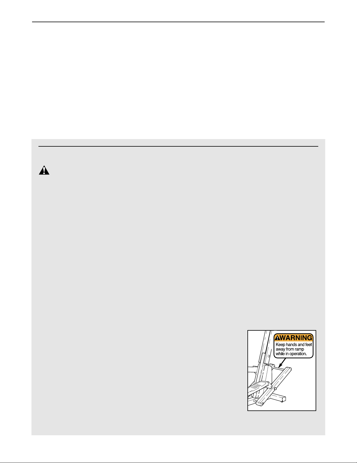
15. If the decal
shown at the
right is missing,
or if it is illegible,
call toll-free
1-888-936-4266
to order a free
replacement
decal. Apply the
decal in the
location shown.
IMPORTANT PRECAUTIONS
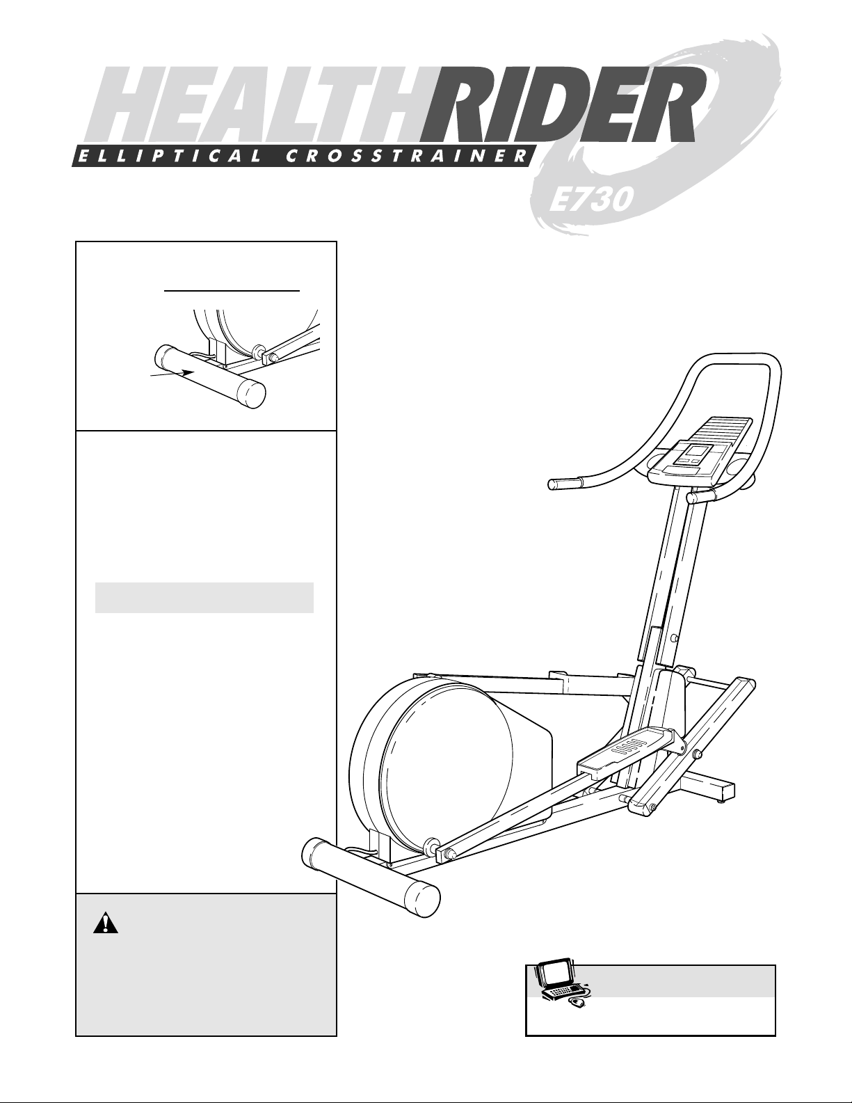
WARNING:
T o reduce the risk of serious injury, read the following important precautions
before using the HealthRider®E730 elliptical crosstrainer.
3
BEFORE YOU BEGIN
Congratulations for selecting the innovative
HealthRider®E730 elliptical crosstrainer. The
HealthRiderE730 is an incredibly smooth exerciser
that moves your feet in a natural elliptical path, minimizing the impact on your knees and ankles. And the
E730 features adjustable resistance and incline and
an advanced console to help you get the most benefit
from your exercise.
For your benefit, read this manual carefully before
you use the elliptical crosstrainer. If you have
questions, call our Customer Service Department tollfree at 1-888-936-4266, Monday through Friday, 8h00
until 18h00 Eastern Time (excluding holidays). To help
us assist you, please mention the product model
number and serial number when calling. The model
number is HRCCEL11900. The serial number is printed on a decal attached to the elliptical crosstrainer
(see the front cover of this manual for the location).
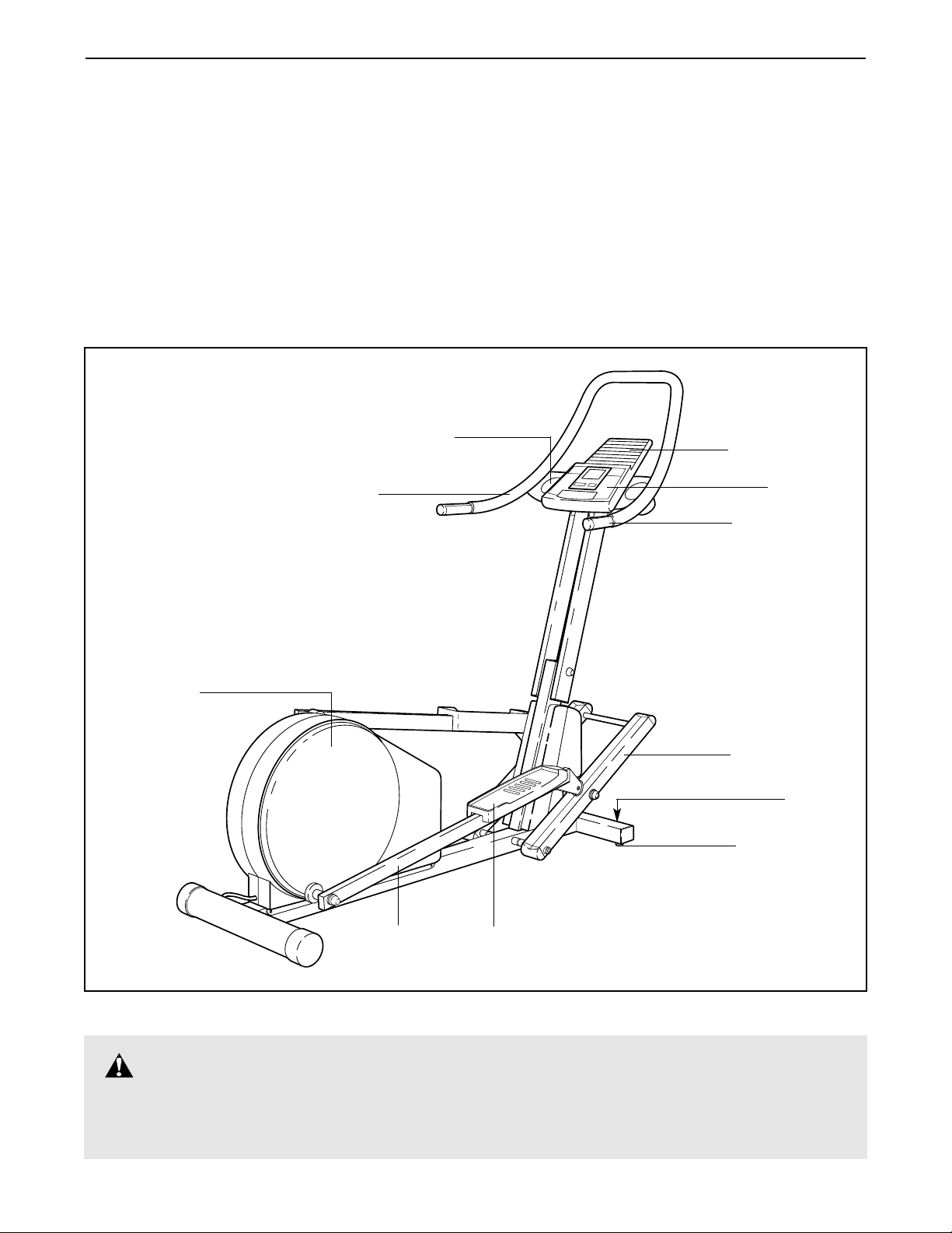
Before reading further, please familiarize yourself with
the parts that are labeled in the drawing below.
Handlebar
FRONT
BACK
RIGHT SIDE
Pedal Leg
Pedal Disk
Pedal
Console
Pulse Sensor
Reading Rack
Leveling Pad
Incline Frame
Roller
Water Bottle Holders
(Bottles not included)
WARNING:Before beginning this or any exercise program, consult your physician.
This is especially important for persons over the age of 35 or persons with pre-existing health
problems. Read all instructions before using. ICON assumes no responsibility for personal injury
or property damage sustained by or through the use of this product.
4
ASSEMBLY
Assembly requires two people. Place all parts of the elliptical crosstrainer in a cleared area and remove the
packing materials. Do not dispose of the packing materials until assembly is completed.
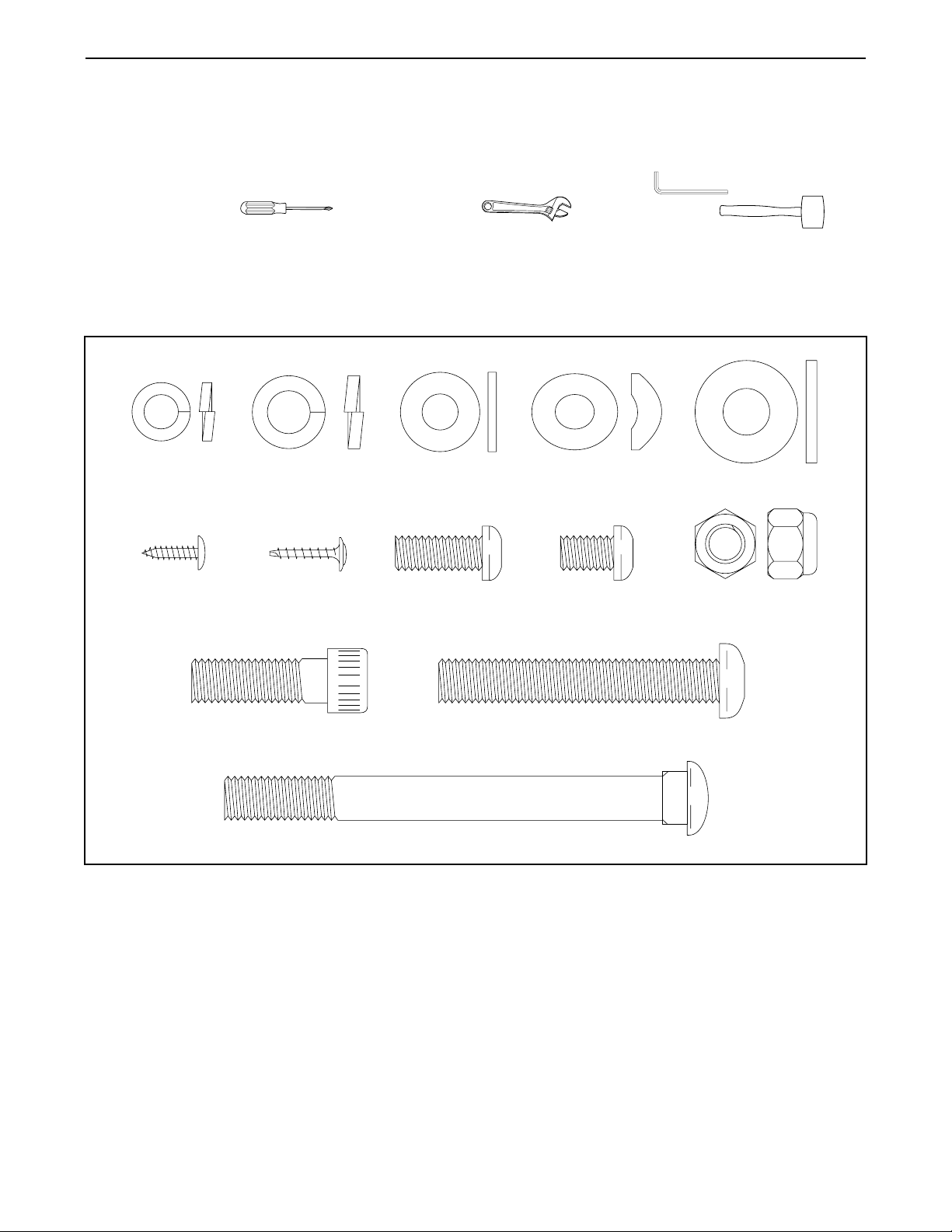
The following tools are required for assembly: the included allen wrenches and your own
phillips screwdriver adjustable wrench and rubber mallet .
As you assemble the elliptical crosstrainer, use the drawings below to identify the small parts used in assembly.
The number in parenthesis below each drawing refers to the key number of the part, from the PART LIST on
page 18. The second number refers to the quantity used in assembly. Note: Some small parts may have been
pre-assembled for shipping. If a part is not in the parts bag, check to see if it has been pre-assembled.
M8 Split
Washer (85)–4
M4 x 16mm
Screw (60)–5
M10 Split
Washer (73)–4
M4 x 16mm
Flange Screw
(88)—6
Patch Bolt (90)–1
M8 Washer
(89)–4
M8 x 19mm Button
Screw (76)–4
Carriage Bolt (2)–2
Curved
Washer (74)–4
Console Plate
Screw (39)–4
Handlebar Bolt (92)–4
M10 Flat
Washer (94)–5
M10 Nylon
Locknut (55)–6
5
3
89
7
14
Motor
Screw
89
85
85
76
76
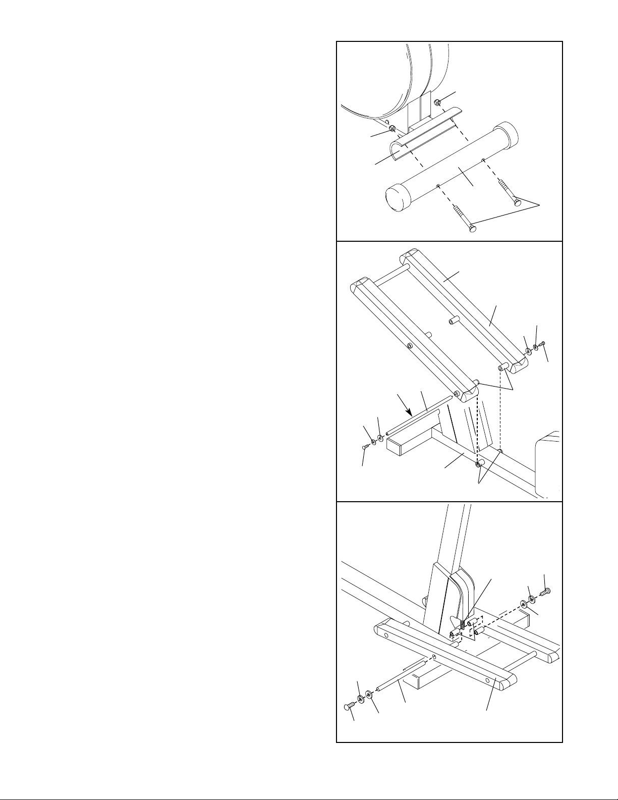
3. Slide an M8 Split Washer (85) and an M8 Washer
(89) onto an M8 x 19mm Button Screw (76). Next,
thread the Button Screw into one end of the Incline
Motor Axle (14). With the help of a second person,
raise the Incline Frame (7). Insert the Incline Motor
Axle through one side of the Incline Frame, through
a Plastic Spacer (91), through the end of the motor
screw, through another Plastic Spacer (91), and
through the other side of the Incline Frame.
Slide an M8 Split Washer (85) and an M8 Washer
(89) onto an M8 x 19mm Button Screw (76). Thread
the Button Screw into the open end of the Incline
Motor Axle (14).
Tighten the four M8 x 19mm Button Screws (76)
used in this step and step 2.
1
1. Hold the Rear Stabilizer (4) against the saddle on the
rear of the Frame (1). Make sure that the Rear Stabiliser is turned so the square holes are facing away
from the Frame. Attach the Rear Stabilizer with two
Carriage Bolts (2) and two M10 Nylon Locknuts (55).
2
4
55
55
1
2
7
V-shaped Groove
15
Grease
89
89
76
76
85
85
1
Tubes
Tubes
2. Slide an M8 Split Washer (85) and an M8 Washer
(89) onto an M8 x 19mm Button Screw (76). Thread
the Button Screw into one end of an Incline Axle
(15). Next, apply a small amount of the included
grease to the Incline Axle.
Align the indicated tubes on the Incline Frame (7)
with the tubes on the Frame (1). Make sure that the
Incline Frame is turned so the V-shaped grooves
are on top. Insert the Incline Axle (15) through the
Incline Frame and the Frame. Note: It may be helpful
to tap the Incline Axle with a rubber mallet to insert
it.
Slide an M8 Split Washer (85) and an M8 Washer (89)
onto another M8 x 19mm Button Screw (76). Thread
the Button Screw into the open end of the Incline
Axle (15). Do not tighten the Button Screws yet.
91
6
6
97
97
Ground
Wire
Console
Wires
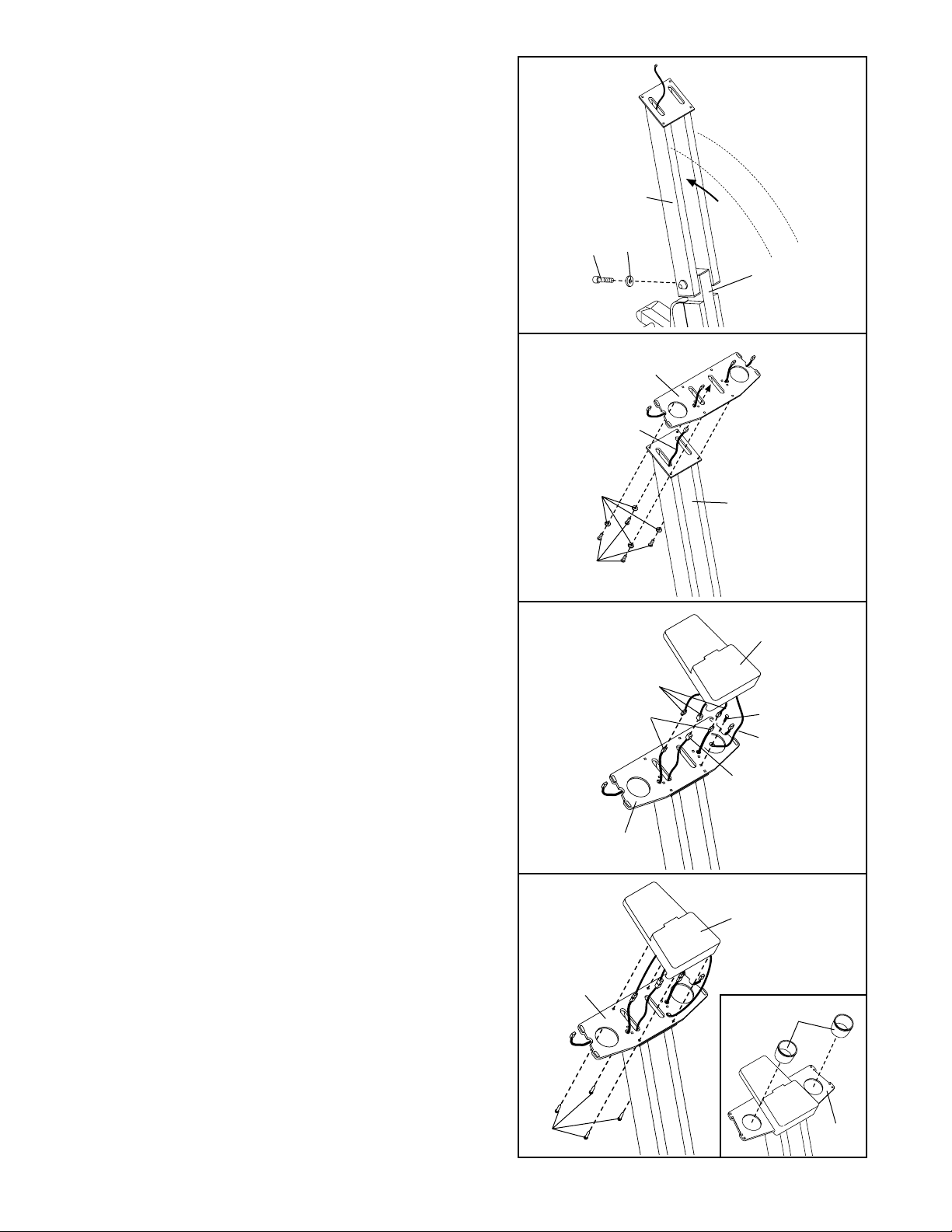
6. Connect the Long Extension Wire (100) to the corresponding wire on the Console (97).
Next, connect the two Console Plate Wires (106) to
the two corresponding wires on the Console (97).
Note: Either Console Plate Wire can be attached to
either wire on the Console.
Next, attach the ground wire to the indicated hole in the
Console Plate (101) with an M4 x 16mm Screw (60).
5. Thread the Long Extension Wire (100) through the
indicated hole in the Console Plate (101). Attach the
Console Plate to the Upright (3) with four Console
Plate Screws (39) and four M10 Split Washers (73).
Make sure that the Long Extension Wire is not
pinched between the Upright and the Console
Plate.
7
87
101
7. Carefully feed all wires down through the Console
Plate (101). Attach the Console (97) to the Console
Plate with four M4 x 16mm Screws (60). Be careful
to avoid pinching the wires.
Refer to the inset drawing. Tap the Water Bottle
Holders (87) into the indicated holes in the Console
Plate (101).
5
101
100
39
73
100
106
101
101
60
3
4
90
94
3
1
4. Raise the Upright (3). Slide the M10 Flat Washer
(94) onto the Patch Bolt (90). Secure the Upright by
tightening the Patch Bolt (90) into the Frame (1).
60
 Loading...