

HealthRider HRC06921 Owner's Manual
CAUTION
Read all precautions and instructions in this manual before using
this equipment. Keep this manual for future reference.
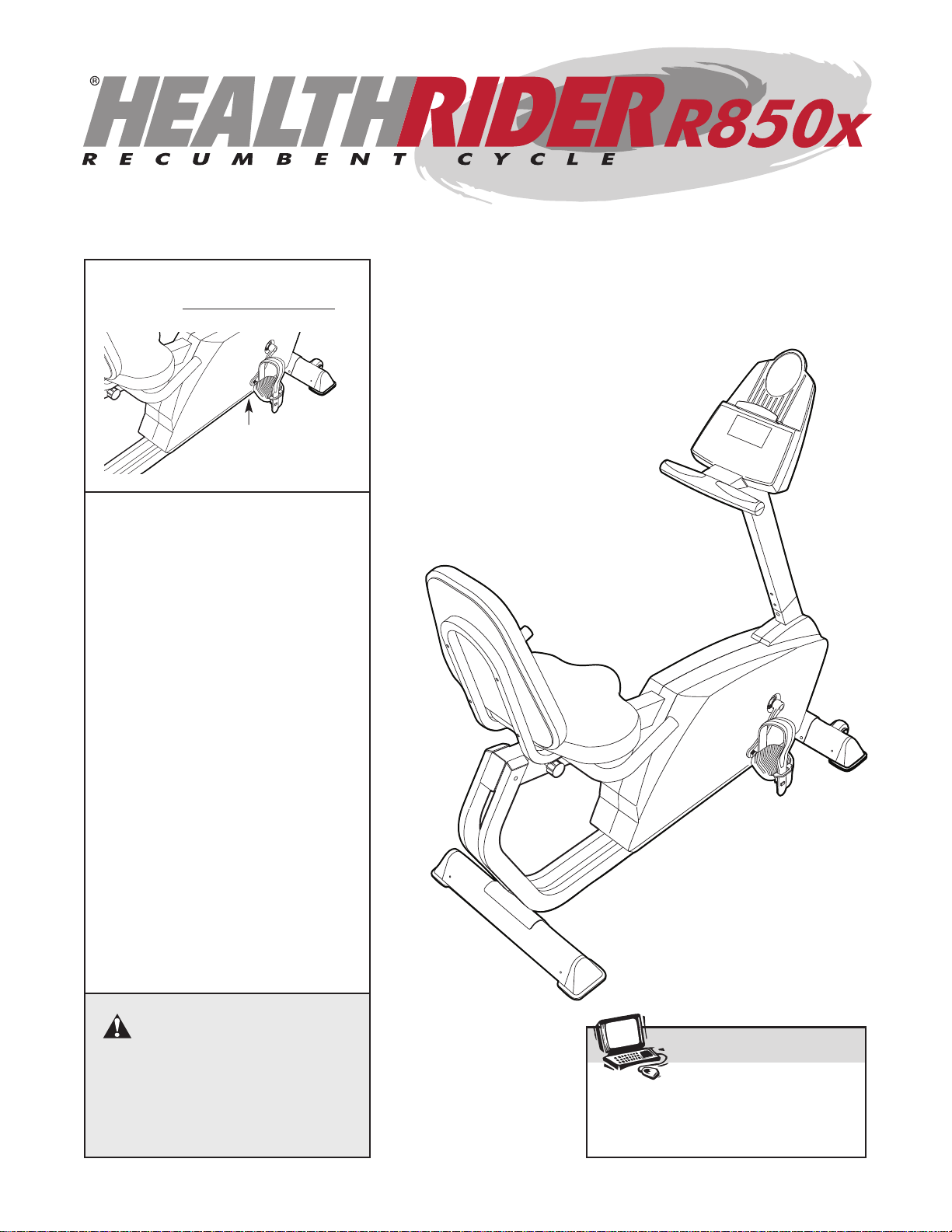
Model No. HRC06921
Serial No.
Serial
Number
Decal
QUESTIONS?
If you have questions, or if there
are missing parts, we will guarantee complete satisfaction
through direct assistance from
our factory.
TO AVOID DELA YS, PLEASE
CALL DIRECT TO OUR TOLLFREE CUSTOMER HOT LINE.
The trained technicians on our
customer hot line will provide
immediate assistance, free of
charge to you.
CUSTOMER HOT LINE:
1-800-999-3756
Mon.–Fri., 6 a.m.–6 p.m. MST
USER’S MANUAL
Visit our website at
www.healthrider.com
new products, prizes,
fitness tips, and much more!

TABLE OF CONTENTS
IMPORTANT PRECAUTIONS . . . . . . . . . . . . . . . . . . . . . . . . . . . . . . . . . . . . . . . . . . . . . . . . . . . . . . . . . . . . .3
BEFORE YOU BEGIN . . . . . . . . . . . . . . . . . . . . . . . . . . . . . . . . . . . . . . . . . . . . . . . . . . . . . . . . . . . . . . . . . . .4
ASSEMBLY . . . . . . . . . . . . . . . . . . . . . . . . . . . . . . . . . . . . . . . . . . . . . . . . . . . . . . . . . . . . . . . . . . . . . . . . . . .5
HOW TO USE THE EXERCISE CYCLE . . . . . . . . . . . . . . . . . . . . . . . . . . . . . . . . . . . . . . . . . . . . . . . . . . . . . .9
MAINTENANCE AND TROUBLESHOOTING . . . . . . . . . . . . . . . . . . . . . . . . . . . . . . . . . . . . . . . . . . . . . . . . .20
CONDITIONING GUIDELINES . . . . . . . . . . . . . . . . . . . . . . . . . . . . . . . . . . . . . . . . . . . . . . . . . . . . . . . . . . . .21
PART LIST . . . . . . . . . . . . . . . . . . . . . . . . . . . . . . . . . . . . . . . . . . . . . . . . . . . . . . . . . . . . . . . . . . . . . . . . . . .22
EXPLODED DRAWING . . . . . . . . . . . . . . . . . . . . . . . . . . . . . . . . . . . . . . . . . . . . . . . . . . . . . . . . . . . . . . . . .23
HOW TO ORDER REPLACEMENT PARTS . . . . . . . . . . . . . . . . . . . . . . . . . . . . . . . . . . . . . . . . . . .Back Cover
LIMITED WARRANTY . . . . . . . . . . . . . . . . . . . . . . . . . . . . . . . . . . . . . . . . . . . . . . . . . . . . . . . . . . .Back Cover
2
HealthRider is a registered trademark of ICON Health & Fitness, Inc.

3
IMPORTANT PRECAUTIONS
WARNING:To reduce the risk of serious injury, read the following important precau-
tions before using the exercise cycle.
1. Read all instructions in this manual before
using the exercise cycle. Use the exercise
cycle only as described.
2. It is the responsibility of the owner to ensure
that all users of the exercise cycle are adequately informed of all precautions.
3. Use the exercise cycle indoors on a level
surface. Keep the exercise cycle away from
moisture and dust. Place a mat under the
exercise cycle to protect the floor or carpet.
4. Inspect and properly tighten all parts regularly. Replace any worn parts immediately.
5. Keep children under the age of 12 and pets
away from the exercise cycle at all times.
6. The exercise cycle should not be used by
persons weighing more than 250 pounds.
7. Wear suitable clothing when using the exercise cycle; do not wear loose clothing that
could become caught on the exercise cycle.
Always wear athletic shoes.
8. Always keep your back straight when using
the exercise cycle. Do not arch your back.
9. If you feel pain or dizziness while exercising, stop immediately and cool down.
10. The pulse sensor is not a medical device.
Various factors, including the user's movement, may affect the accuracy of heart rate
readings. The pulse sensor is intended only
as an exercise aid in determining heart rate
trends in general.
11. The exercise cycle is intended for in-home
use only. Do not use the exercise cycle in a
commercial, rental, or institutional setting.
WARNING:Before beginning this or any exercise program, consult your physician.
This is especially important for persons over the age of 35 or persons with pre-existing health problems. Read all instructions before using. ICON assumes no responsibility for personal injury or
property damage sustained by or through the use of this product.
4
BEFORE YOU BEGIN
Congratulations for selecting the new Healthrider
®
R850X exercise cycle. Cycling is one of the most
effective exercises for increasing cardiovascular fitness, building endurance, and toning the entire body.
The R850X exercise cycle offers an impressive array
of features designed to let you enjoy this healthful
exercise in the comfort and privacy of your home.
For your benefit, read this manual carefully before
you use the exercise cycle. If you have questions
after reading this manual, call our Customer Service
Department toll-free at 1-800-999-3756, Monday
through Friday, 6 a.m. until 6 p.m. Mountain Time
(excluding holidays). To help us assist you, mention
the product model number and serial number when
calling. The model number is HRC06921. The serial
number can be found on a decal attached to the exercise cycle (see the front cover of this manual for the
location of the decal).
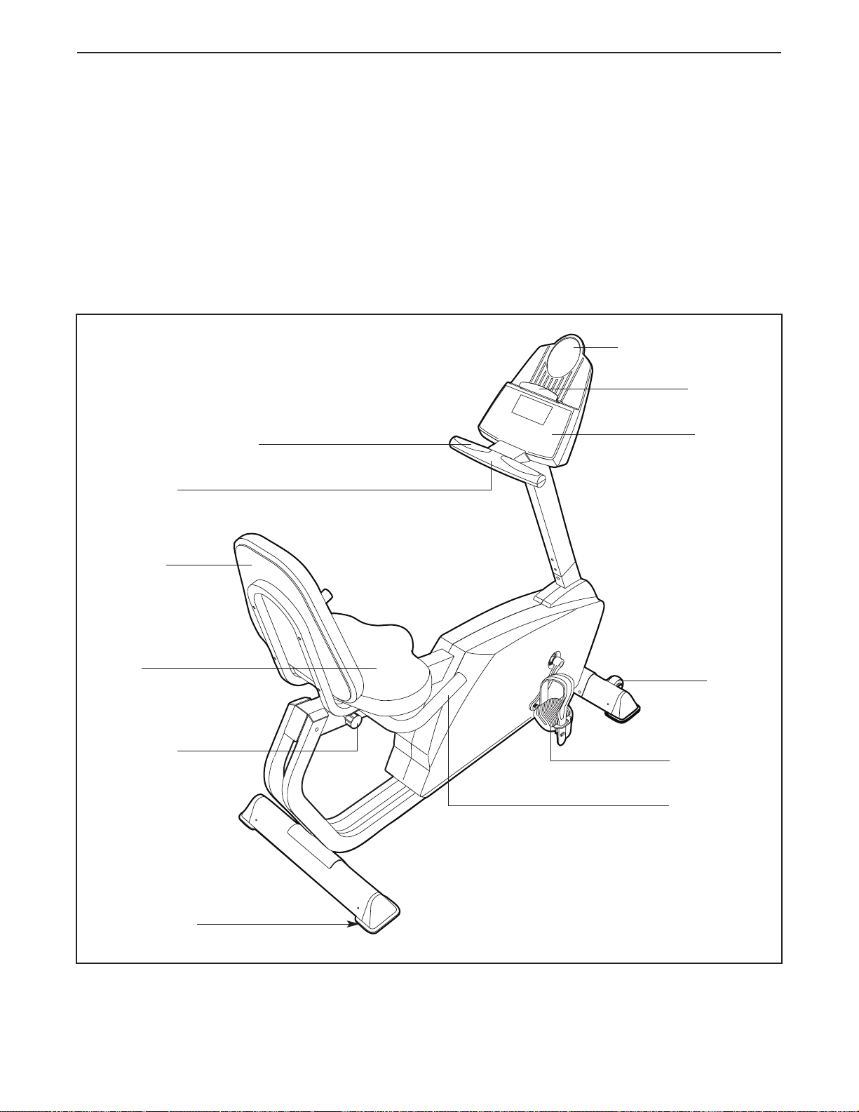
Before reading further, please familiarize yourself with
the parts that are labeled in the drawing below.
Handgrip Pulse Sensor
BACK
FRONT
RIGHT SIDE
*No water bottle is included
Wheel
Pedal /Strap
Console
Bookrack
Water Bottle Holder*
Backrest
Seat
Seat Handle
Seat Knob
Leveling Foot
Handlebar
5
ASSEMBLY
Assembly requires two persons. Place all parts of the exercise cycle in a cleared area and remove the pack-
ing materials. Do not dispose of the packing materials until assembly is completed.
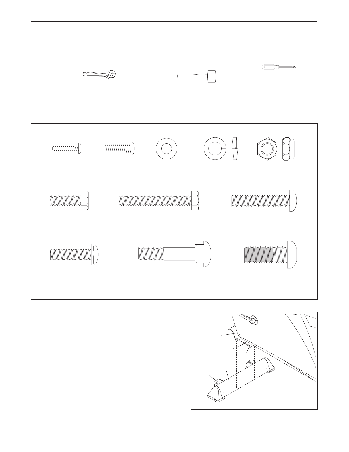
In addition to the included allen wrenches, assembly requires a phillips screwdriver , an
adjustable wrench , and a rubber mallet .
As you assemble the exercise cycle, use the drawings below to identify the small parts used in assembly. The
number in parenthesis below each drawing refers to the key number of the part, from the PART LIST on page
22. The second number refers to the quantity used in assembly. Note: Some small parts may have been pre-
assembled for shipping. If a part is not in the parts bag, check to see if it has been pre-assembled.
1. Identify the Front Stabilizer (9), which has Wheels (31)
attached to it. While another person lifts the front of the
Frame (1), attach the Front Stabilizer to the Frame
with two M8 x 25mm Button Screws (47) and two M8
Split Washers (52).
9
47
52
31
1
1
M4 x 16mm
Screw (63)–2
1/4” x 19mm
Screw (59)–4
M8 x 25mm Button
Screw (47)–8
M5 x 16mm
Screw (62)–2
M6 Washer
(56)–8
1/4” x 45mm
Screw (55)–4
M8 x 40mm Carriage
Bolt (57)–2
M8 Split
Washer (52)–8
M8 Nylon Jamnut
(82)–4
M8 x 36mm Button
Bolt (81)–2
M10 x 27mm
Patch Screw (51)–3
6
3
2
1
74
39
47
47
52
52
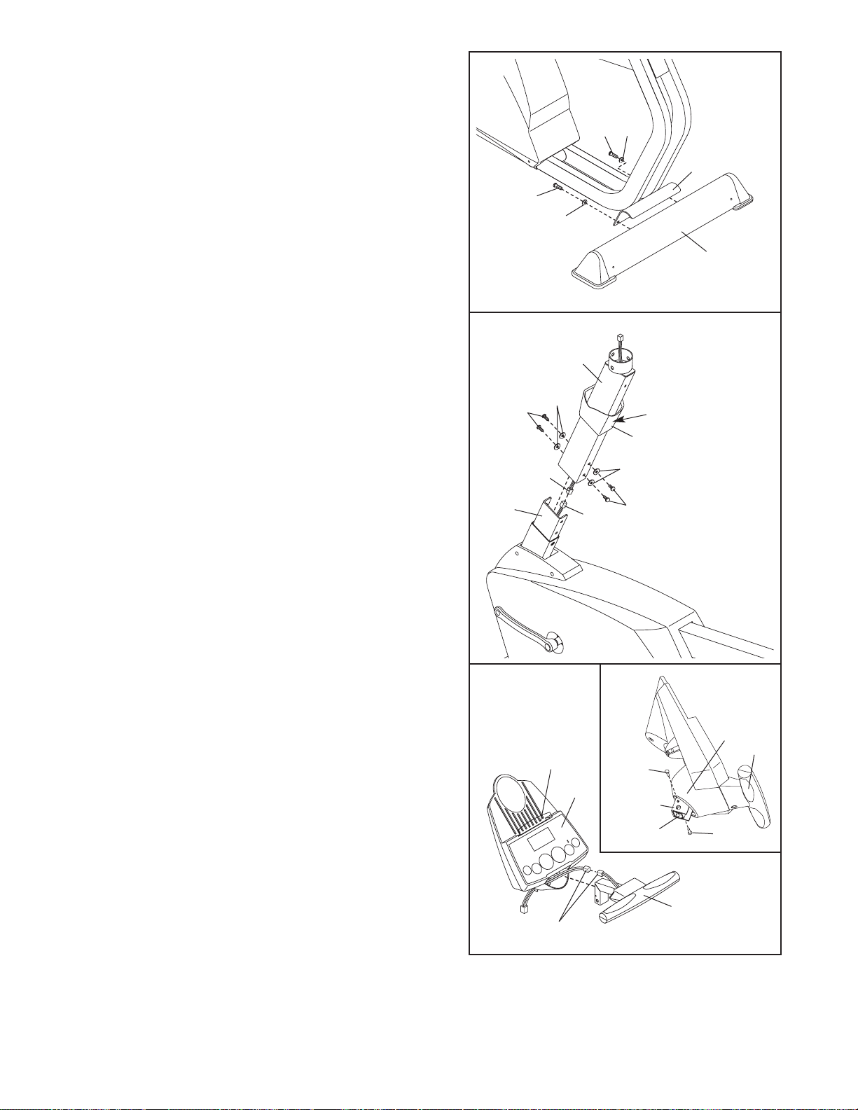
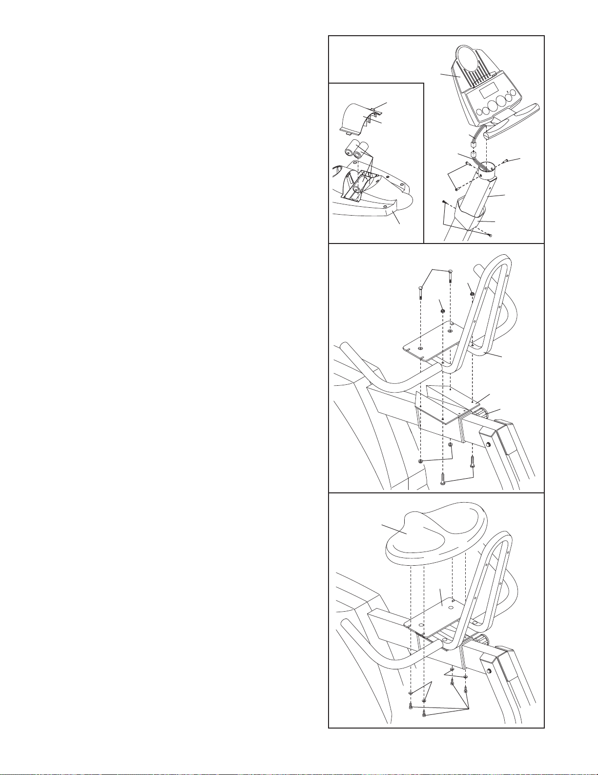
3. Slide the Console Collar (6) up onto the Upright (2).
Make sure that the Console Collar is oriented exactly
as shown, with the decal on the indicated side.
While another person holds the Upright (2) in the position shown, connect the Upper Wire Harness (39) to
the Lower Wire Harness (74). Carefully pull the
upper end of the Upper Wire Harness to remove
any slack. While holding the Upper Wire Harness,
slide the Upright onto the Frame (1). Be careful not to
pinch the Wire Harnesses.
Attach the Upright (2) to the Frame (1) with four M8 x
25mm Button Screws (47) and four M8 Split Washers
(52).
4. Connect the wire harness on the Handgrip Pulse
Sensor (5) to the indicated wire harness on the
Console (4). Insert both wire harnesses into the opening in the bottom of the Console.
Refer to the inset drawing. Insert the metal tube on the
Handgrip Pulse Sensor (5) into the metal bracket inside
the Console (4) as shown. Be careful not to pinch the
wire harnesses. Align the holes in the metal tube with
the holes in the metal bracket, and tighten two M4 x
16mm Screws (63) into the indicated holes.
Snap the bookrack onto the Console (4) in the location
shown.
5
4
Bookrack
Wire Harnesses
4
Make sure the
Wire Harnesses
(39, 74) do not
get pinched dur-
ing this step.
63
Bracket
Tube
63
5
4
6
Decal
2. While another person lifts the Rear Frame (3), attach
the Rear Stabilizer (10) to the Rear Frame with two
M8 x 25mm Button Screws (47) and two M8 Split
Washers (52).
10
2
47
47
52
52
3
7
7. Attach the Seat (14) to the Seat Frame (13) with four
1/4” x 19mm Screws (59) and four M6 Washers (56).
59
56
14
13
7
6. Attach the front of the Seat Frame (13) to the Seat
Carriage (12) with two M8 x 40mm Carriage Bolts (57)
and two M8 Nylon Jamnuts (82). Do not tighten the
Nylon Jamnuts yet.
Attach the back of the Seat Frame (13) to the Seat
Carriage (12) with two M8 x 36mm Button Bolts (81)
and two M8 Nylon Jamnuts (82). Note: The Button
Bolts must be inserted from below to provide maximum clearance around the Seat Knob (34).
Tighten all four M8 Nylon Jamnuts (82).
13
82
81
57
82
82
12
34
6
5. The Console (4) requires four “D” batteries (not included); alkaline batteries are recommended. Refer to the
inset drawing. Press the tab on the battery cover, and
lift off the battery cover. Insert four batteries into the
battery compartment. Make sure that the batteries
are oriented as shown by the diagram inside the
battery compartment. Reattach the battery cover.
While another person holds the Console (4), connect
the wire harness on the Console to the Upper Wire
Harness (39). Insert the wire harnesses down into the
Upright (2). Attach the Console to the Upright with
three M10 x 27mm Patch Screws (51). Be careful to
avoid pinching the wire harnesses.
Slide the Console Collar (6) to the top of the Upright
(2). Attach the Console Collar with two M5 x 16mm
Screws (62).
4
39
51
51
2
6
Wire
Harness
62
4
Tab
Batteries
Battery
Cover
5
8
10.Make sure that all parts of the exercise cycle are properly tightened. Note: Some hardware may be left
over after assembly is completed. To protect the floor or carpet from damage, place a mat under the exercise
cycle.
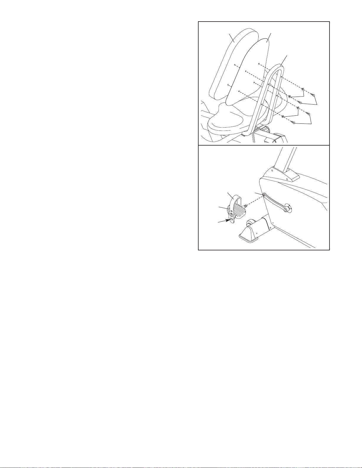
9. Identify the Left Pedal (16), which is marked with an
“L.” Using an adjustable wrench, firmly tighten the
Left Pedal counterclockwise into the Left Crank Arm
(22). Tighten the Right Pedal (not shown) clockwise
into the Right Crank Arm. Important: Tighten both
Pedals as firmly as possible. After using the
exercise cycle for one week, retighten the
Pedals. For best performance, the Pedals must
be kept tightened.
Identify the Left Pedal Strap (18), which is marked
with an “L.” Attach the Left Pedal Strap to the Left
Pedal (16). Press the end of the Left Pedal Strap
onto the tab on the Left Pedal. Attach and adjust the
Right Pedal Strap (not shown) in the same way.
22
16
18
Tab
9
8. Attach the Backrest (15) and the Backrest Cover
(77) to the Seat Frame (13) with four 1/4” x 45mm
Screws (55) and four M6 Washers (56).
15
77
13
55
56
8
56
55
 Loading...