

HealthRider HF-XT9800-E1 Owner's Manual
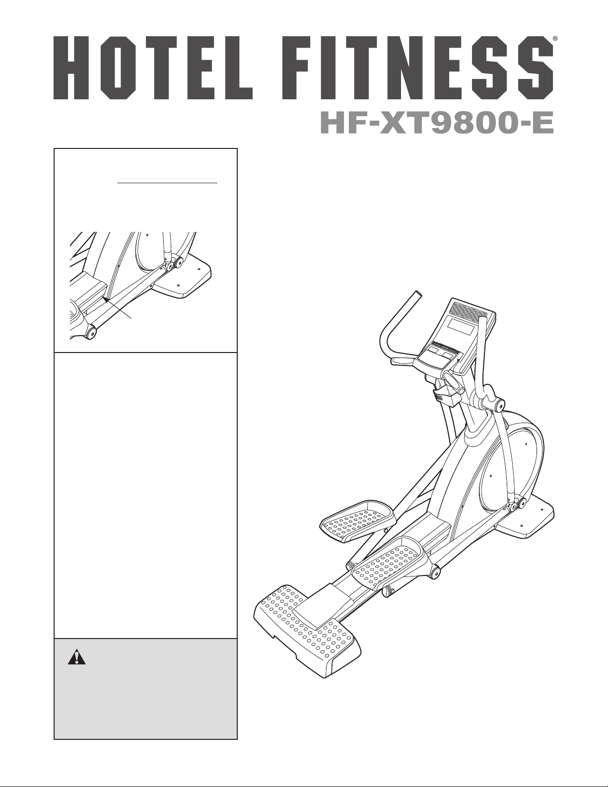
Model No. HF-XT9800-E.1
Serial No.
Write the serial number in the
space above for reference.
Serial Number Decal
QUESTIONS?
If you have questions, or if parts
are damaged or missing, please
see HOW TO CONTACT CUSTOMER CARE on the back cover
of this manual.
USERʼS MANUAL
CAUTION
Read all precautions and instructions in this manual before using
this equipment. Keep this manual
for future reference.
www.HotelFitness.com
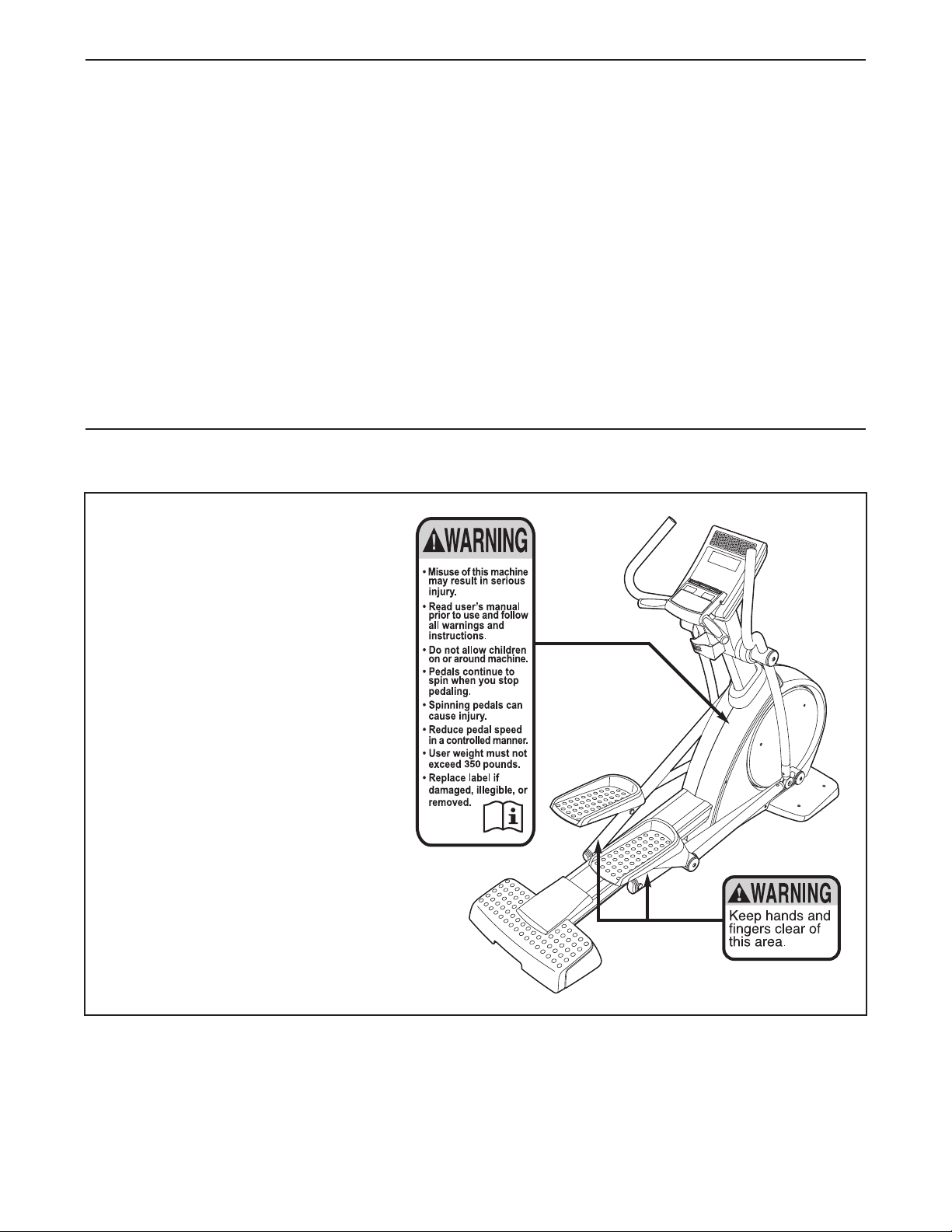
TABLE OF CONTENTS
WARNING DECAL PLACEMENT . . . . . . . . . . . . . . . . . . . . . . . . . . . . . . . . . . . . . . . . . . . . . . . . . . . . . . . . . . . . . .2
IMPORTANT PRECAUTIONS . . . . . . . . . . . . . . . . . . . . . . . . . . . . . . . . . . . . . . . . . . . . . . . . . . . . . . . . . . . . . . . .3
BEFORE YOU BEGIN . . . . . . . . . . . . . . . . . . . . . . . . . . . . . . . . . . . . . . . . . . . . . . . . . . . . . . . . . . . . . . . . . . . . . .4
ASSEMBLY . . . . . . . . . . . . . . . . . . . . . . . . . . . . . . . . . . . . . . . . . . . . . . . . . . . . . . . . . . . . . . . . . . . . . . . . . . . . . . .5
OW TO UPGRADE THE CONSOLE . . . . . . . . . . . . . . . . . . . . . . . . . . . . . . . . . . . . . . . . . . . . . . . . . . . . . . . . .10
H
HOW TO USE THE ELLIPTICAL . . . . . . . . . . . . . . . . . . . . . . . . . . . . . . . . . . . . . . . . . . . . . . . . . . . . . . . . . . . . .11
MAINTENANCE AND TROUBLESHOOTING . . . . . . . . . . . . . . . . . . . . . . . . . . . . . . . . . . . . . . . . . . . . . . . . . . .28
EXERCISE GUIDELINES . . . . . . . . . . . . . . . . . . . . . . . . . . . . . . . . . . . . . . . . . . . . . . . . . . . . . . . . . . . . . . . . . . .29
PART LIST . . . . . . . . . . . . . . . . . . . . . . . . . . . . . . . . . . . . . . . . . . . . . . . . . . . . . . . . . . . . . . . . . . . . . . . . . . . . . .31
EXPLODED DRAWING . . . . . . . . . . . . . . . . . . . . . . . . . . . . . . . . . . . . . . . . . . . . . . . . . . . . . . . . . . . . . . . . . . . .33
HOW TO CONTACT CUSTOMER CARE . . . . . . . . . . . . . . . . . . . . . . . . . . . . . . . . . . . . . . . . . . . . . . .Back Cover
LIMITED WARRANTY . . . . . . . . . . . . . . . . . . . . . . . . . . . . . . . . . . . . . . . . . . . . . . . . . . . . . . . . . . . . . .Back Cover
WARNING DECAL PLACEMENT
This drawing shows the location(s)
of the warning decal(s). If a decal is
missing or illegible, see the back
cover of this manual and request
a free replacement decal. Apply
the decal in the location shown.
Note: The decal(s) may not be
shown at actual size.
HOTEL FITNESS is a registered trademark of Hotel Fitness Club, Inc.
FREEMOTION is a registered trademark of ICON IP, Inc.
2

IMPORTANT PRECAUTIONS
WARNING: T
instructions in this manual and all warnings on your elliptical before using your elliptical. Hotel
Fitness and FreeMotion Fitness assume no responsibility for personal injury or property damage
sustained by or through the use of this product.
1. Before beginning any exercise program,
consult your physician. This is especially
important for persons over age 35 or persons with pre-existing health problems.
2. Use the elliptical only as described in this
manual.
3. It is the responsibility of the owner to
ensure that all users of the elliptical are adequately informed of all precautions.
4. Keep the elliptical indoors, away from moisture and dust. Do not place the elliptical in a
garage or covered patio or near water.
5. Place the elliptical on a level surface. To
protect the floor or carpet from damage,
place a mat beneath the elliptical. Make sure
that there is at least 3 ft. (0.9 m) of clearance
in the front and rear of the elliptical and 2 ft.
(0.6 m) on each side.
6. Inspect and properly tighten all parts regularly. Replace any worn parts immediately.
7. Keep children under age 12 and pets away
from the elliptical at all times.
8. The elliptical should not be used by persons
weighing more than 350 lbs. (159 kg).
9. Wear appropriate clothes while exercising;
do not wear loose clothes that could
o reduce the risk of serious injury, read all important precautions and
become caught on the elliptical. Always
wear athletic shoes for foot protection.
10. Hold the handgrip pulse sensor or the handlebars when mounting, dismounting, or
using the elliptical.
11. Keep your back straight while using the
elliptical; do not arch your back.
12. The pulse sensor is not a medical device.
Various factors, including the userʼs movement, may affect the accuracy of heart rate
readings. The pulse sensor is intended only
as an exercise aid in determining heart rate
trends in general.
13. The elliptical does not have a freewheel; the
pedals will continue to move until the flywheel stops. Reduce your pedaling speed in
a controlled way.
14. Over exercising may result in serious injury
or death. If you feel faint or if you experience pain while exercising, stop
immediately and cool down.
15. Do not modify the power adapter or use an
adapter to connect the power adapter to an
improper receptacle. Keep the power
adapter away from heated surfaces. Do not
use an extension cord.
3
BEFORE YOU BEGIN
Thank you for selecting the new HOTEL FITNESS
F-XT9800-E elliptical. The HF-XT9800-E elliptical
H
provides an impressive selection of features designed
to help you achieve your fitness goals.
For your benefit, read this manual carefully before
you use the elliptical. If you have questions after
reading this manual, please see the back cover of this
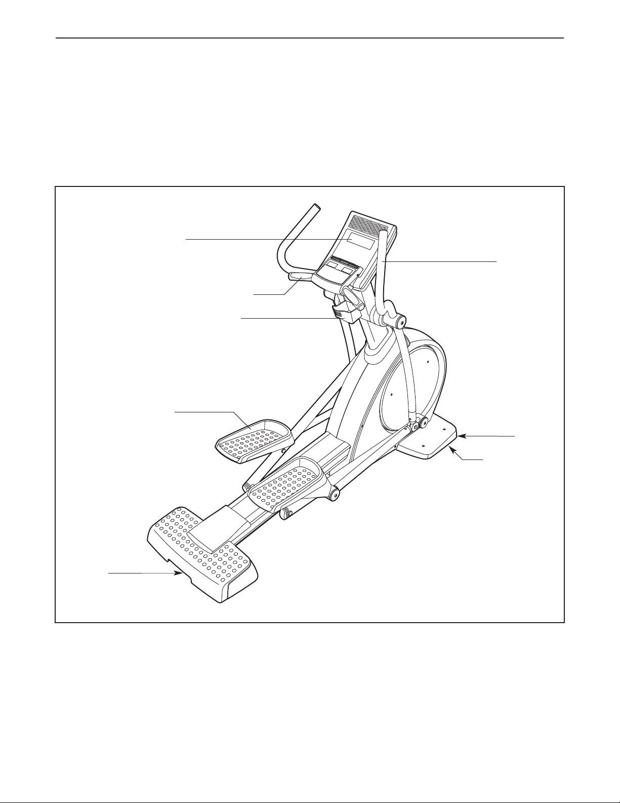
Console
Handgrip Pulse Sensor
Water Bottle Holder*
®
manual. To help us assist you, note the product num-
er and serial number before contacting us. The
b
model number and the location of the serial number
are shown on the front cover this manual.
Before reading further, please familiarize yourself with
the parts that are labeled in the drawing below.
Handlebar
Handle
Pedal
Wheel
Leveling Foot
*Water bottle is not included
4
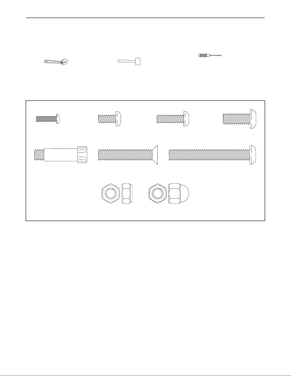
M6 x 20mm
Screw (68)–4
M6 x 13mm
Screw (84)–2
M8 x 20mm
Screw (60)–8
M4 x 15mm
Screw (52)–4
M8 x 32mm
Screw (63)–2
M8 x 60mm
Screw (88)–2
M8 x 40mm Bolt
(65)–4
M8 Locknut
(54)–2
M8 Acorn
Nut (99)–4
ASSEMBLY
Assembly requires two persons. Place all parts of the elliptical in a cleared area and remove the packing
materials. Do not dispose of the packing materials until assembly is completed.
In addition to the included tool(s), assembly requires a Phillips screwdriver , an adjustable
wrench , and a rubber mallet .
See the drawings below to identify the small parts needed for assembly. The number in parentheses below each
drawing is the key number of the part, from the PART LIST near the end of this manual. The number following
the key number is the quantity needed for assembly. Note: If a part is not in the hardware kit, check to see if
it has been preassembled. To avoid damaging parts, do not use power tools for assembly.
5
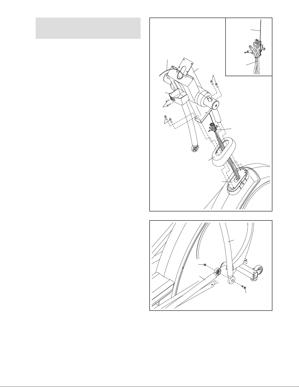
1.
To make assembly easier, read the
nformation on page 5 before you begin.
i
Orient the Shield Cover (39) and the Upright (2)
s shown. Slide the Shield Cover upward onto
a
the Upright.
Have a second person hold the Upright (2) near
the Frame (1).
1
Wire Tie
Wire Tie
2
60
A
See the inset drawing. Locate the wire tie in
the Upright (2). Tie the lower end of the wire tie
to the frame wires (A). Next, pull the upper end
of the wire tie upward out of the top of the
Upright. Tip: To prevent the frame wires from
falling into the Upright, secure the frame
wires with the wire tie.
Tip: Avoid pinching the wires. Attach the
Upright (2) to the Frame (1) with four M8 x
20mm Screws (60). Tip: Start all the Screws
before tightening any of them.
Then, slide the Shield Cover (39) downward to
the bottom of the Upright (2).
Attach the Water Bottle Holder (19) to the
Upright (2) with two M4 x 15mm Screws (52).
2. Attach the Right Handlebar Leg (32) to the Right
Pedal Arm (28) with an M8 x 32mm Screw (63)
and an M8 Locknut (54). Do not overtighten
the Locknut; the Right Pedal Arm must pivot
easily.
19
52
60
Avoid pinching
the wires
2
A
39
1
32
Attach the Left Handlebar Leg (not shown) to
the Left Pedal Arm (not shown) in the same
way.
54
28
63
6
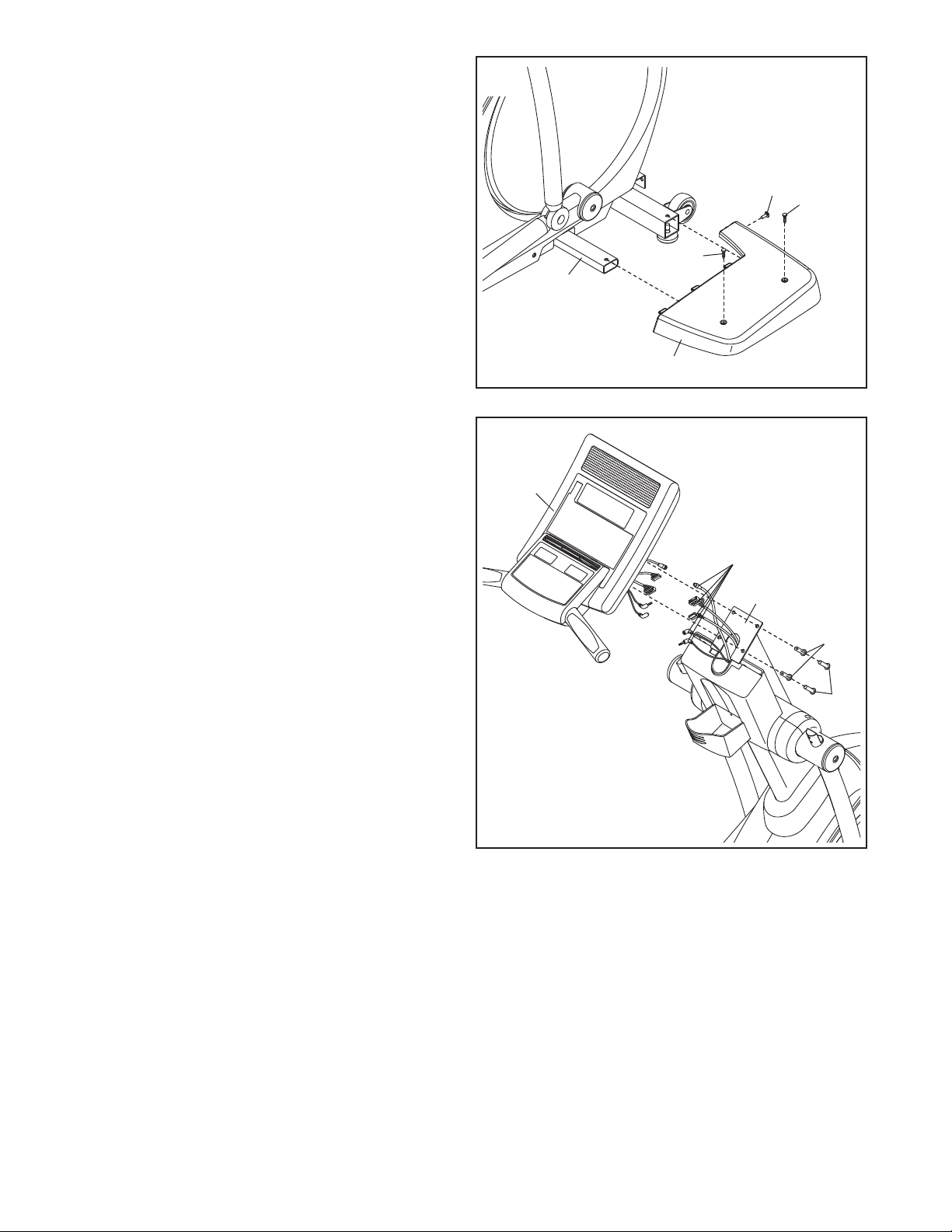
3. Identify the Right Frame Cover (8), and orient it
as shown.
ttach the Right Frame Cover (8) to the Frame
A
(1) with two M6 x 20mm Screws (68) and an M6
13mm Screw (84).
x
3
Attach the Left Frame Cover (not shown) in
the same way.
4. While a second person holds the Console (6)
near the Upright (2), connect the wires on the
Console to the frame wires (A). Insert the
excess wire downward into the Upright.
Note: Some of the wires are for the optional
Workout TV (see page 10).
Tip: Avoid pinching the wires. Attach the
Console (6) to the Upright (2) with four M8 x
20mm Screws (60).
84
68
68
1
8
4
6
Avoid pinching
the wires
A
2
60
60
7
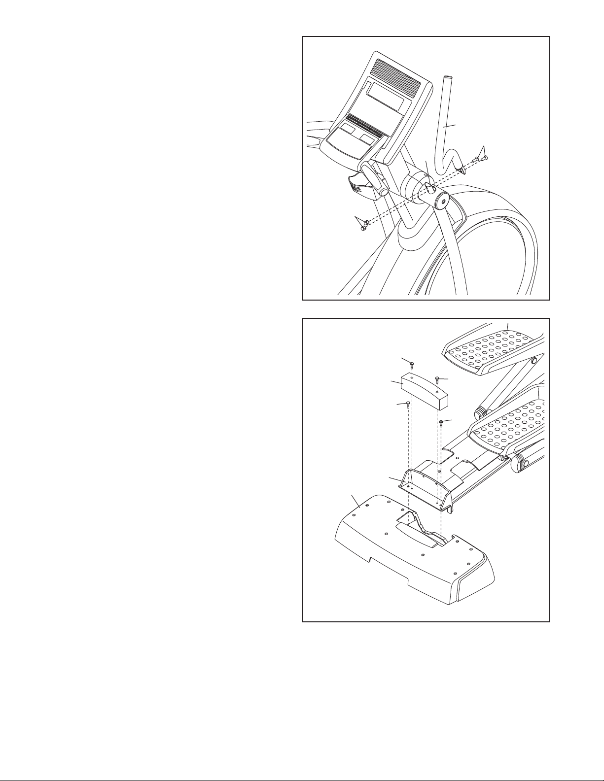
5. Identify the Right Handlebar (35), which is
marked with an “R” sticker.
ttach the Right Handlebar (35) to the Right
A
Handlebar Leg (32) with two M8 x 40mm Bolts
65) and two M8 Acorn Nuts (99). First, tighten
(
the Bolts completely into the Right
Handlebar and the Right Handlebar Leg.
Using the hex key, hold the Bolts firmly
against the Right Handlebar and then tighten
the Acorn Nuts onto the ends of the Bolts.
Attach the Left Handlebar (not shown) to the
Left Handlebar Leg (not shown) in the same
way.
5
5
3
65
32
99
6. Attach the Rear Stabilizer Cover (5) to the
Stabilizer Bracket (86) with two M8 x 60mm
Screws (88).
Attach the Stabilizer Block (90) to the Stabilizer
Bracket (86) with two M4 x 15mm Screws (52).
6
52
90
88
86
5
52
88
8
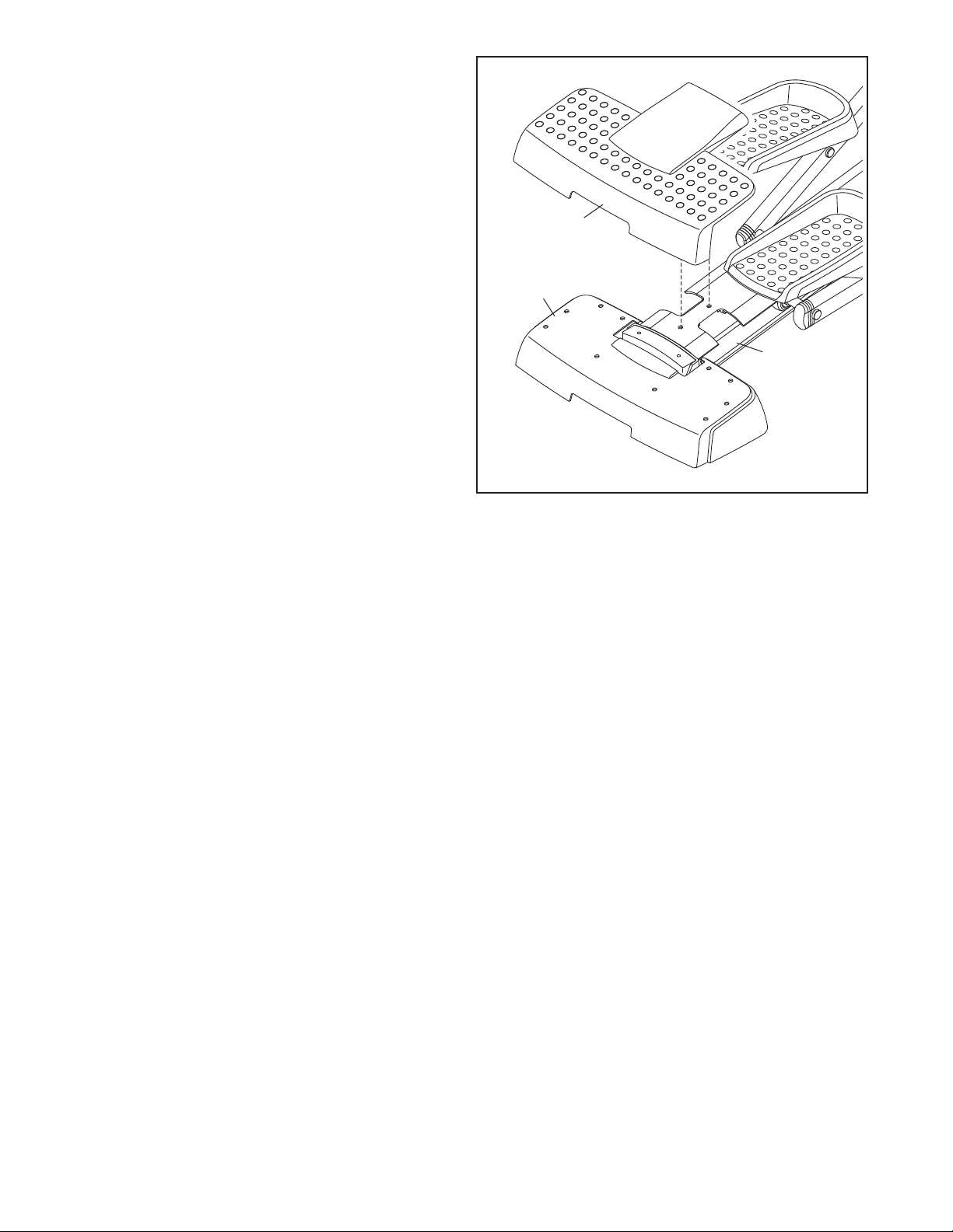
7. Remove the adhesive backing from the Rear
Stabilizer Overlay (10) and from the Rear
Stabilizer Cover (5).
Press the Rear Stabilizer Overlay (10) onto the
rack Frame (3) and the Rear Stabilizer Cover
T
(5).
7
10
5
3
8. Make sure that all parts of the elliptical are properly tightened. Note: Some hardware may be left over
after assembly is completed. To protect the floor or carpet from damage, place a mat under the elliptical.
9
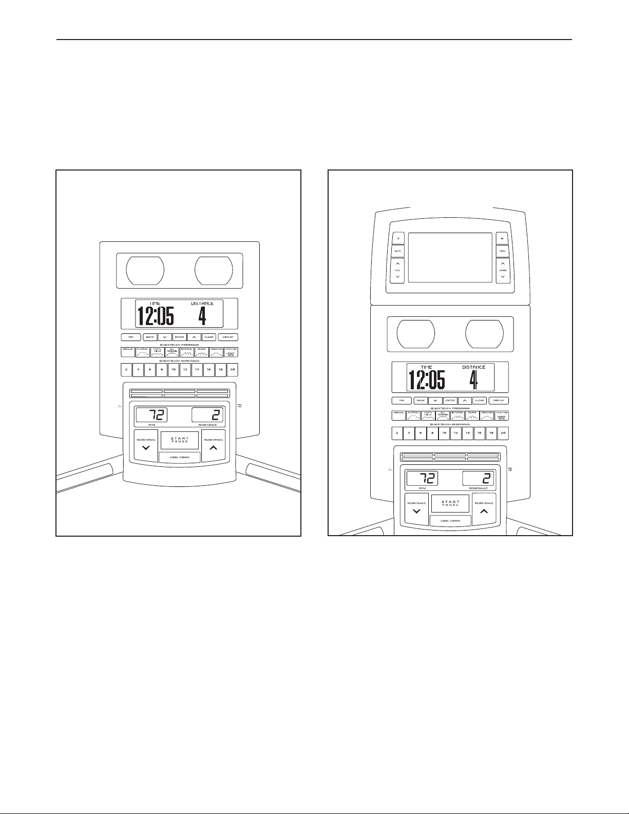
HOW TO UPGRADE THE CONSOLE
The elliptical has been preconfigured to operate with a Basic console and a Workout TV console (see the drawings below). To learn about the features of the Basic console, see page 13. To learn about the features of the
Workout TV console, see the userʼs manual included with the Workout TV console.
To upgrade your console and expand the capabilities of the elliptical whenever you choose, please see
the back cover of this manual.
Basic
Console
Workout TV
Console
10
HOW TO USE THE ELLIPTICAL
HOW TO PLUG IN THE POWER ADAPTER
o use the power adapter, first plug one end of the
T
power adapter into the receptacle on the front of the
elliptical. Plug the other end of the power adapter into
an appropriate outlet that is properly installed in accordance with all local codes and ordinances.
HOW TO CONNECT A CATV CABLE
Power Adapter
Receptacle
If the elliptical has a Workout TV console (see HOW
TO UPGRADE THE CONSOLE on page 10), a CATV
cable must be connected to the elliptical for cable TV
stations to be viewed. Locate the cable jack on the
front of the elliptical. Connect the CATV cable to the
cable jack.
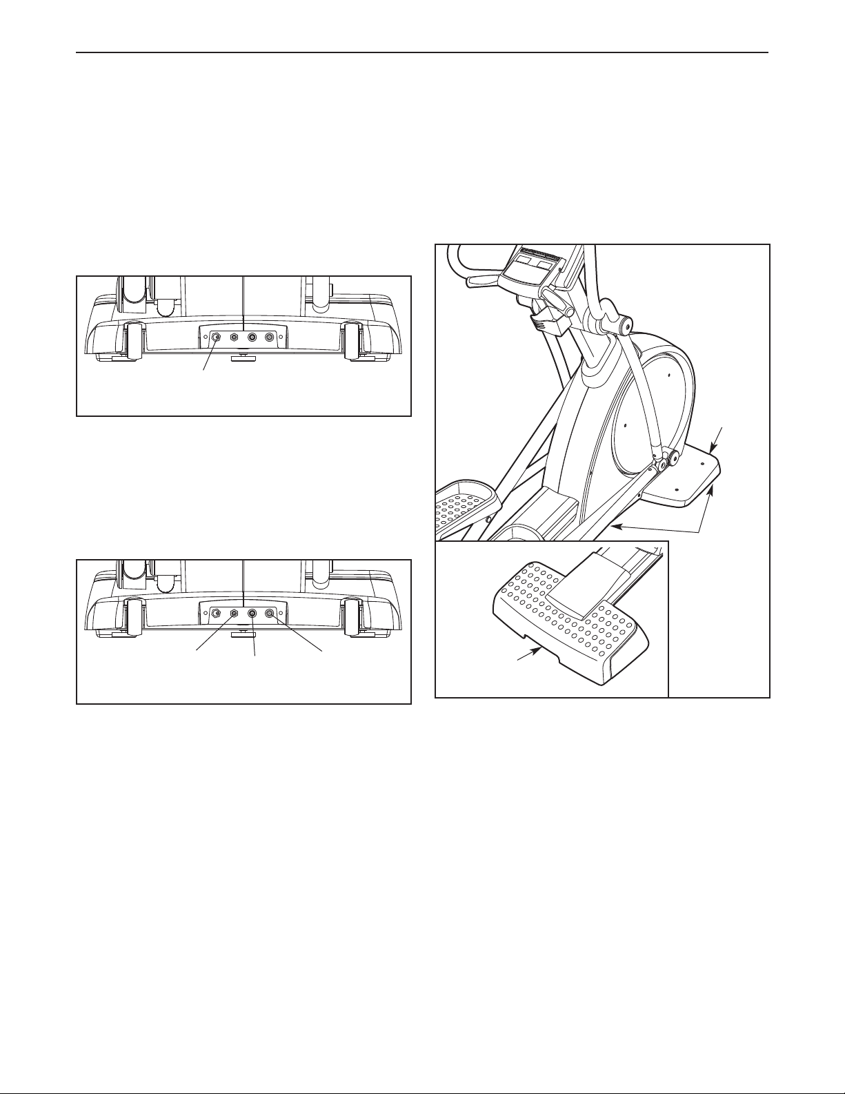
HOW TO MOVE THE ELLIPTICAL
ue to the size and weight of the elliptical, moving
D
it requires two persons. Have two persons lift the
indicated end of the elliptical until the elliptical will roll
on the front wheels. Carefully move the elliptical to the
desired location and then lower it to the level position.
Wheel
Leveling
Feet
Cable Jack
Jack to External
Speaker System
A satellite receiver, VCR, or DVD player can also be
connected to the elliptical. Connect a CATV cable from
the coaxial output on your equipment to the cable
jack. Note: Audio/video equipment without coaxial outputs (some satellite receivers and DVD players) will
require an RF modulator to operate with the elliptical.
RF modulators and external CATV cables are not
available from FreeMotion Fitness, but are available at
electronics stores. See the owner's manual included
with the equipment you wish to connect to see
whether an RF modulator is needed.
Audio/Video
Jack
Lift here
CAUTION: To decrease the risk of injury, bend
your legs and keep your back straight. Make sure
to use your legs rather than your back to lift the
elliptical. Do not attempt to move the elliptical
over an uneven surface.
HOW TO LEVEL THE ELLIPTICAL
If the elliptical rocks slightly on your floor during use,
turn one or both of the leveling feet beneath the front
stabilizer until the rocking motion is eliminated. Then,
turn the leveling foot beneath the center of the frame
to prevent the frame from flexing.
11
 Loading...