

Healthrider HETL62140 User Manual
Model No. HETL62140
www.iconeurope.com
Visit our website at
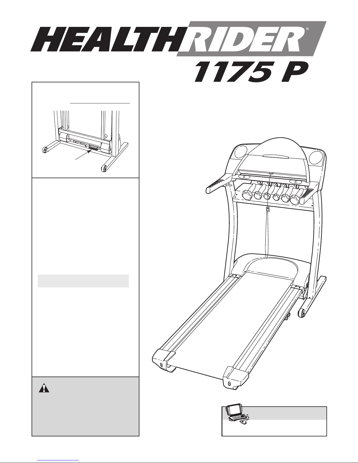
Serial No.
Serial
Number
Decal
QUESTIONS?
As a manufacturer, we are
committed to providing
complete customer satisfaction.
If you have questions, or if
there are missing parts, we will
guarantee complete satisfaction
through our Customer Service
Department.
USER'S MANUAL
Please call:
08457 089 009
Or write:
ICON Health & Fitness, Ltd.
Unit 4
Revie Road Industrial Estate
Revie Road
Beeston
Leeds
LS11 8JG
CAUTION
Read all precautions and instructions in this manual before using
this equipment. Save this manual
for future reference.

TABLE OF CONTENTS
IMPORTANT PRECAUTIONS . . . . . . . . . . . . . . . . . . . . . . . . . . . . . . . . . . . . . . . . . . . . . . . . . . . . . . . . . . . . . . . . .3
BEFORE YOU BEGIN . . . . . . . . . . . . . . . . . . . . . . . . . . . . . . . . . . . . . . . . . . . . . . . . . . . . . . . . . . . . . . . . . . . . . . .5
ASSEMBLY . . . . . . . . . . . . . . . . . . . . . . . . . . . . . . . . . . . . . . . . . . . . . . . . . . . . . . . . . . . . . . . . . . . . . . . . . . . . . . .6
HOW TO USE THE CHEST PULSE SENSOR . . . . . . . . . . . . . . . . . . . . . . . . . . . . . . . . . . . . . . . . . . . . . . . . . . .10
OPERATION AND ADJUSTMENT . . . . . . . . . . . . . . . . . . . . . . . . . . . . . . . . . . . . . . . . . . . . . . . . . . . . . . . . . . . .11
HOW TO FOLD AND MOVE THE TREADMILL . . . . . . . . . . . . . . . . . . . . . . . . . . . . . . . . . . . . . . . . . . . . . . . . . .24
TROUBLESHOOTING . . . . . . . . . . . . . . . . . . . . . . . . . . . . . . . . . . . . . . . . . . . . . . . . . . . . . . . . . . . . . . . . . . . . . .26
CONDITIONING GUIDELINES . . . . . . . . . . . . . . . . . . . . . . . . . . . . . . . . . . . . . . . . . . . . . . . . . . . . . . . . . . . . . . .29
ORDERING REPLACEMENT PARTS . . . . . . . . . . . . . . . . . . . . . . . . . . . . . . . . . . . . . . . . . . . . . . . . . .Back Cover
Note: A n EXPLODED DRAWING and a PART LIST are attached in the centre of this manual.
HealthRider is a registered trademark of ICON IP, Inc.
2

IMPORTANT PRECAUTIONS
WARNING: To reduce the risk of burns, fire, electric shock, or injury to persons, read the
following important precautions and information before operating the treadmill.
1. It is the responsibility of the owner to ensure
that all users of this treadmill are adequately
informed of all warnings and precautions.
2. Use the treadmill only as described in this
manual.
3. This treadmill is intended for in-home use
only. Do not use this treadmill in a commercial, rental, or institutional setting.
4. Place the treadmill on a level surface, with at
least 2.5 m (8 ft.) of clearance behind it and
0.5 m (2 ft.) on each side. Do not place the
treadmill on a surface that blocks any air
openings. To protect the floor or carpet from
damage, place a mat under the treadmill.
5. Keep the treadmill indoors, away from moisture and dust. Do not put the treadmill in a
garage or covered patio, or near water.
6. Do not operate the treadmill where aerosol
products are used or where oxygen is being
administered.
7. Keep children under the age of 12 and pets
away from the treadmill at all times.
8. The treadmill should be used only by persons
weighing 115 kg (250 lbs.) or less.
9. Never allow more than one person on the
treadmill at a time.
Wear appropriate exercise clothes when
10.
using the treadmill. Do not wear loose clothes
that could become caught in the treadmill.
Athletic support clothes are recommended for
both men and women.
shoes. Never use the treadmill with bare feet,
wearing only stockings, or in sandals.
11. When connecting the power cord (see page
11), plug the power cord into an earthed circuit. No other appliance should be on the same
circuit. When replacing the fuse, an ASTA approved BS1362 type should be fitted to the
fuse carrier. A 13 amp fuse should be used.
Always wear athletic
13. Keep the power cord away from heated surfaces.
14. Never move the walking belt whilst the power
is turned off. Do not operate the treadmill if
the power cord or plug is damaged, or if the
treadmill is not working properly. (See
BEFORE YOU BEGIN on page 5 if the treadmill is not working properly.)
15. Never start the treadmill whilst you are standing on the walking belt. Always hold the
handrails whilst using the treadmill.
16. The treadmill is capable of high speeds.
Adjust the speed in small increments to avoid
sudden jumps in speed.
17. The pulse sensors are not medical devices.
Various factors, including the user's movement, may affect the accuracy of heart rate
readings. The pulse sensors are intended
only as exercise aids in determining heart
rate trends in general.
18. Do not use the hand weights at speeds faster
than walking speeds. Using weights and not
holding the handrails may compromise your
ability to maintain your balance. Exercises
using weights should be attempted only by
experienced users.
19. Never leave the treadmill unattended whilst it
is running. Always remove the key, unplug
the power cord, and move the on/off switch to
the off position when the treadmill is not in
use. (See the drawing on
tion of the on/off switch.)
20. Do not attempt to raise, lower, or move the
treadmill until it is properly assembled. (See
ASSEMBLY on page 6, and HOW TO FOLD
AND MOVE
must be able to safely lift 20 kg (45 lbs.) to
raise, lower, or move the treadmill.
21. Do not change the incline of the treadmill by
placing objects under the treadmill.
THE TREADMILL on page 24.) You
page 5 for the loca
-
12. If an extension cord is needed, use only a 3conductor, 1mm
longer than 1.5 m (5 ft.).
2
(14-gauge) cord that is no
22. When folding or moving the treadmill, make
sure that the storage latch is fully closed.
3
Never insert or drop any object into any
23.
opening.
24. When using iFIT.com CDs and videos, an
electronic “chirping” sound will alert you
when the speed and/or incline of the treadmill
is about to change. Always listen for the
“chirp” and be prepared for speed and/or incline changes. In some instances, the speed
and/or incline may change before the personal trainer describes the change.
25. When using iFIT.com CDs and videos, you
can manually override the speed and incline
settings at any time by pressing the speed
and incline buttons. However, when the next
“chirp” is heard, the speed and/or incline will
change to the next settings of the CD or video
program.
Always remove iFIT.com CDs and videos from
26.
your CD player or VCR when you are not
using them.
Inspect and properly tighten all parts of the
27.
treadmill regularly.
DANGER: Always unplug the power
28.
cord immediately after use, before cleaning
the treadmill, and before performing the maintenance and adjustment procedures described in this manual. Never remove the
motor hood unless instructed to do so by an
authorised service representative. Servicing
other than the procedures in this manual
should be performed by an authorised service
representative only.
WARNING: Before beginning this or any exercise program, consult your physician. This
is especially important for persons over the age of 35 or persons with pre-existing health problems.
Read all instructions before using. ICON assumes no responsibility for personal injury or property
damage sustained by or through the use of this product.
SAVE THESE INSTRUCTIONS
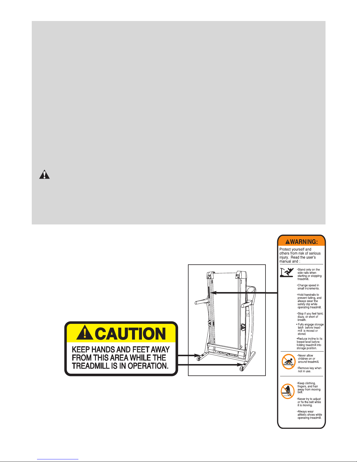
The decals shown below have been placed on the treadmill. If a decal is missing, or
if it is not legible, please call our Customer Service Department (see the back cover
of this manual) and order a free replacement decal. Apply the decal in the location
shown.
Note: The decal shown at the
right is 50% of actual size.
4
BEFORE YOU BEGIN
Thank you for selecting the new HealthRider®1175 P
treadmill. The 1175 P treadmill combines advanced
technology with innovative design to help you get the
most from your exercise program in the convenience of
your home. And when you’re not exercising, the unique
1175 P treadmill can be folded up, requiring less than
half the floor space of other treadmills.
For your benefit, read this manual carefully before
using the treadmill. If you have questions after read-
ing this manual, please call our Customer Service
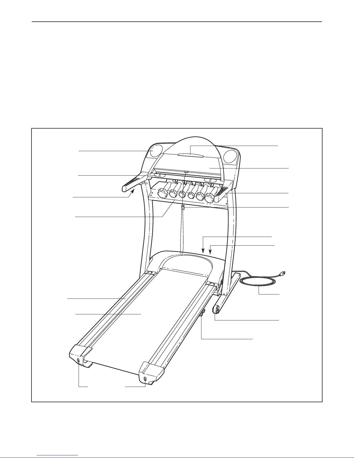
Water Bottle
Holder (Bottle
not included)
Pulse Sensor
Latch Knob
Weight Rack
Department at
please note the product model number and serial number before calling. The model number is HETL62140.
The serial number can be found on a decal attached to
the treadmill (see the front cover of this manual for the
location).
Before reading further, please review the drawing
below and familiarise yourself with the parts that are
labelled.
08457 089 009. To help us assist you,
Book Holder
Console
Handrail
Key/Clip
LEFT SIDE
Foot Rail
Walking Belt
Circuit Breaker
On/Off Switch
RIGHT SIDE
Power Cord
Front Wheel
Adjustable Cushioned
Walking Platform
Rear Roller
Adjustment Bolts
5
ASSEMBLY
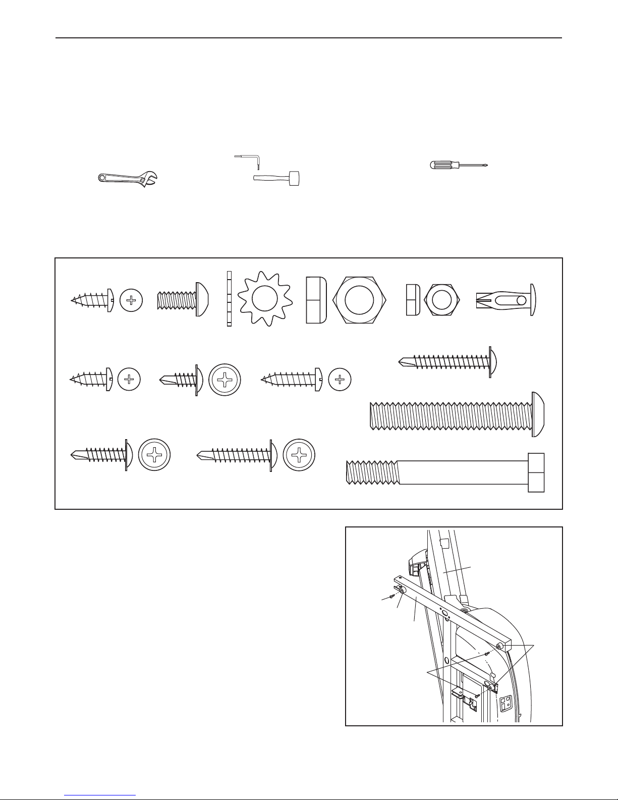
Nut (3)–2
Star Washer
(111)–4
3/4” Tek Screw
(35)–6
3/4” Screw (37)–20
1/2” Tek Screw
(113)–2
1/2” Screw
(33)–4
1/2” Silver
Screw (114)–2
Plastic Fastener
(9)–4
Rack Bolt
(132)–4
Rack Nut
(133)–4
1 1/4” Tek Screw (138)–2
1” Tek Screw (13)–6
Upright Bolt (112)–4
Wheel Bolt (56)–2
Assembly requires two persons. Set the treadmill in a cleared area and remove all packing materials; do not
dispose of the packing materials until assembly is completed. Note: The underside of the treadmill walking
belt is coated with high-performance lubricant. During shipping, a small amount of lubricant may be transferred to
the top of the walking belt or the shipping carton. This does not affect treadmill performance. If there is lubricant
on top of the walking belt, simply wipe off the lubricant with a soft cloth and a mild, non-abrasive cleaner.To protect the floor or carpet from damage, place a mat under the treadmill.
Assembly requires the included hex key and your own phillips screwdriver , adjustable
spanner , and rubber mallet .
As you assemble the treadmill, use the drawings below to identify hardware. Note: The hardware is packaged
in separate parts bags. Each parts bag is marked to show which assembly steps require the hardware in
that parts bag. Do not open the parts bags until instructed to do so. If a part is not found in the parts
bags, check to see if it has been preassembled. Some part bags may include extra hardware.
1. Do not plug in the power cord until all assembly
steps are completed.
With the help of a second person, carefully tip the
treadmill onto its left side as shown. Partially fold the
Frame (51) so the treadmill will be more stable.
fully fold the treadmill until it is completely assem-
bled.
Open parts bag 1–2. Attach the six Base Pads (44) to
the bottom of the Base (116) with six 1” Tek Screws (13).
Note: Only three Tek Screws are shown.
Do not
1
51
13
44
6
116
13
44
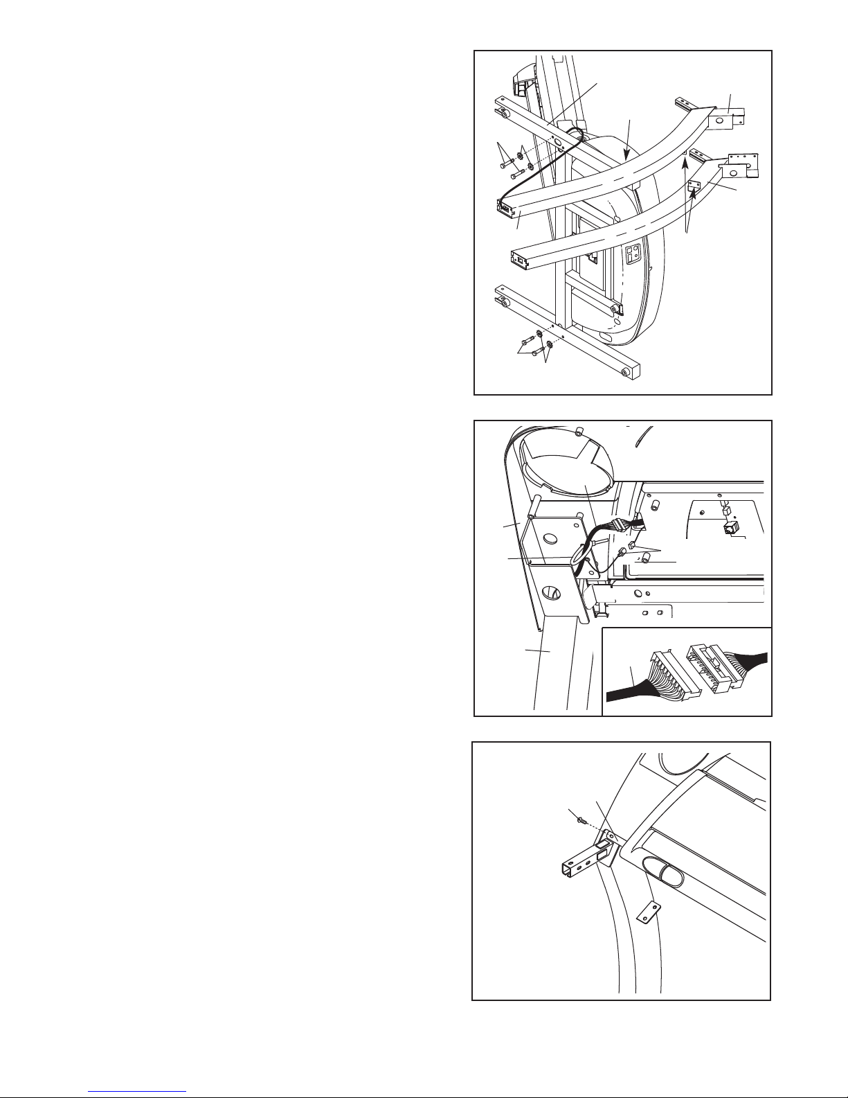
2. Identify the Right and Left Uprights (55, 64); the brackets
on the Uprights should be positioned as shown.
Hold the Right Upright (55) near the Base (116), and orient the Right Upright as shown.
Right Upright bends in the direction shown.
Make sure that the
Straighten
the Wire Harness (49), and feed it into the lower end of
the Right Upright and out of the upper end. Make sure
that the Wire harness is not pinched. Hand tighten two
Upright Bolts (112) with Star Washers (111) into the bottom of the Base (116) and the lower end of the Right
Upright.
Attach the Left Upright (64) as described above. Note:
There is not a wire harness on the left side.
3. With the help of a second person, carefully tip the treadmill back down so that the Uprights (55, 64 [not shown])
are vertical. Make sure that the end of the Wire
Harness (49) does not fall into the Right Upright.
2
112
112
3
111
49
116
55
Bend
64
Brackets
111
Remove the plastic ties holding the Console Base (38)
and Console Back (not shown) together.
Set the Console Base (38) on the Right Upright (55) as
shown. Check the pins in the connector on the Wire
Harness (49) and make sure that they are straight.
Connect the Wire Harness to the indicated connector on
the back of the Console Base. Make sure to insert the
connectors properly (see the inset drawing). The connectors should slide together easily and snap into
place. If the connectors do not slide together easily and
snap into place, turn one connector and try again.
Insert the included plastic tie through the small hole in the
Right Upright (55) and around the Wire Harness (49) as
shown. Connect the two indicated ground wires.
4. Open parts bag 4–5. Loosely thread a 1/2” Tek Screw
(113) into the left side of the Crossbar (46) and the Left
Upright (64). Note: The Tek Screw may be preassembled
in the Left Upright.
38
Tie
55
4
113
(Leave loose)
49
Ground Wires
49
46
7
5. Loosely thread a 1/2” Tek Screw (113) into the right side
of the Crossbar (46) and the Right Upright (55).
5
38
Attach the Console Base (38) to the Uprights (55, 64) with
four 1/2” Screws (33).
Make sure that the Wire Harness
(49) is not pinched. Insert any excess Wire Harness into
the Right Upright. Securely tighten the plastic tie around
the Wire Harness and cut off the end of the tie.
Tighten the 1/2” Tek Screws (113) in steps 4 and 5.
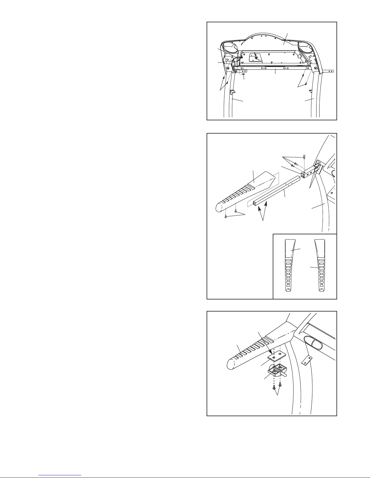
6. Open parts bag 6–9. Turn a Handrail Extension (34) so
the two larger holes are on the bottom. Insert the
Handrail Extension as far as possible into the post on the
left Upright (64). If necessary, tap the Handrail Extension
with a rubber mallet to fully insert it. Next, attach the
Handrail Extension by tightening three 3/4” Tek Screws
(35) into the indicated holes.
Identify the Left Foam Grip (31) (see the inset drawing).
Remove the paper from the two indicated blocks of
Foam Tape (82). Apply a small amount of water to the
blocks of Foam Tape. Slide the Left Foam Grip as far as
possible onto the post on the left Upright (64). (Note: It
may be helpful to lubricate the Handrail Extension
[34] with soapy water.) Press two Plastic Fasteners (9)
into the Foam Grip and the Handrail Extension. If necessary, use a blunt object to press in the Fasteners.
49
Tie
6
33
113
55
31
9
46
33
64
35
Post
82
34
64
Holes
31
Attach the other Handrail Extension (not shown) and the
Right Foam Grip (43) as described above. Note: Make
sure that the 3/4” Tek Screws (35) are attached on the
outside of the post as shown.
Attach the Latch Assembly (32) and the Latch Spacer
7.
(100) to the Left Handrail (31) with two 1 1/4” Tek
Screws (138) as shown. Make sure that the Latch
Spacer is oriented with the lip on the side shown.
43
7
Lip
31
100
32
138
8
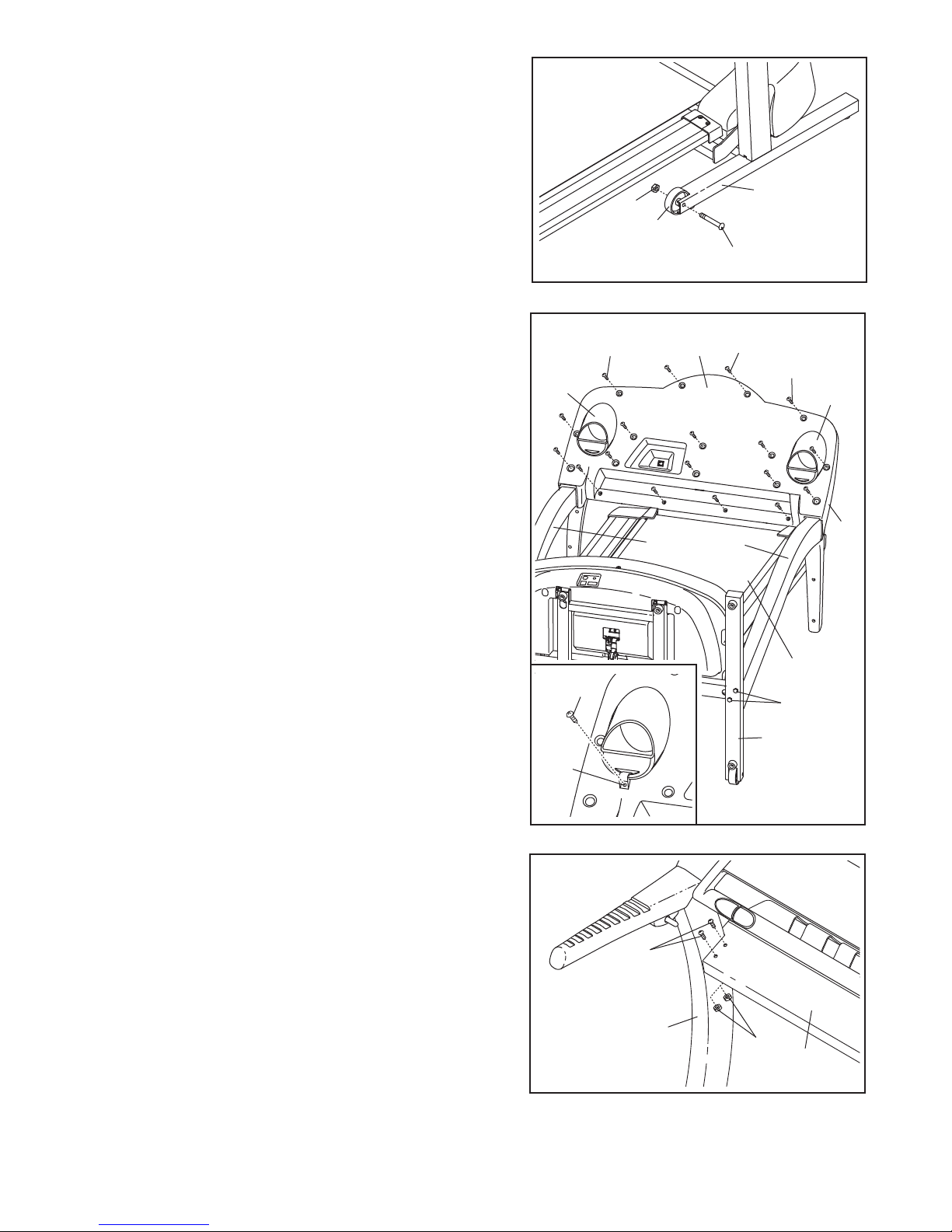
8. Attach a Wheel (58) to the right side of the Base (116)
with a Wheel Bolt (56) and a Nut (3) as shown.
Attach a Wheel to the left side of the Base (not shown) in
the same way.
8
9. Carefully lower the Uprights (55, 64) as shown.
Open parts bag 10. Press the Console Back (40) onto
the back of the Console Base (38). Make sure that
Console Back and the Console Base are mated correctly and that no wires are pinched. Tighten two 1/2”
Silver Screws (114) into the indicated holes. Tighten 3/4”
Screws (37) into the other holes in the Console Back.
Insert the Left and Right Cup Holders (39, 50) into the
large holes in the Console Base (38). If there is a small
hole under each Cup Holder, the two Small Clamps (117)
should be attached. See the inset drawing. Loop a Small
Clamp through the hole in the bottom of a Cup Holder and
attach it with a 3/4” Screw (37). Attach a Small Clamp to
the other Cup Holder in the same way.
Raise the Uprights (55, 64) back to the vertical position.
3
116
58
56
9
114
40
37
114
39
50
38
55
64
10.Attach the Weight Rack (110) to the Left Upright (64) and
the Right Upright (not shown) with four Rack Bolts (132)
and four Rack Nuts (133). Do not tighten the Rack
Bolts Yet.
See step 9.
Carefully lower the Uprights (55, 64) as
shown. Make sure that the deck is centred between the
Uprights. Firmly tighten—but do not overtighten—the four
Upright Bolts (112) (only two are shown) in the Base (116).
Raise the Uprights (55, 64) back to the vertical position.
Tighten the four Weight Rack Bolts (132).
117
10
37
132
64
116
133
Deck
112
110
11.Make sure that all parts are properly tightened before you use the treadmill. Keep the included hex key
in a secure place; the hex key is used to adjust the walking belt (see page 27).
9
HOW TO USE THE CHEST PULSE SENSOR
HOW TO PUT ON THE CHEST PULSE SENSOR
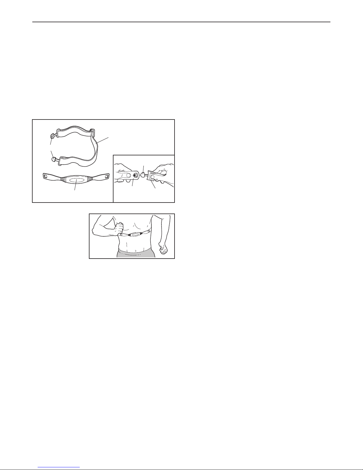
The chest pulse sensor consists of two components:
the chest strap and the sensor unit (see the drawing
below). Insert the tab on one end of the chest strap into
one end of the sensor unit, as shown in the inset drawing. Press the end of the sensor unit under the buckle
on the chest strap. The tab should be flush with the
front of the sensor unit.
Chest Strap
Tabs
Tab
Sensor Unit
Next, wrap the
chest pulse sensor around your
chest and attach
the other end of
the chest strap to
the sensor unit.
Adjust the length
of the chest strap, if necessary. The chest pulse sensor should be under your clothes, tight against your
skin, and as high under the pectoral muscles or
breasts as is comfortable. Make sure that the logo on
the sensor unit is facing forward and is right-side-up.
Pull the sensor unit away from your body a few inches
and locate the two electrode areas on the inner side
(the electrode areas are covered by shallow ridges).
Using saline solution such as saliva or contact lens solution, wet both electrode areas. Return the sensor unit
to a position against your chest.
Sensor
Unit
Buckle
• Store the chest pulse sensor in a warm, dry place.
Do not store the chest pulse sensor in a plastic bag
or other container that may trap moisture.
• Do not expose the chest pulse sensor to direct
sunlight for extended periods of time; do not expose
it to temperatures above 50° C (122° F) or below
-10° C (14° F) .
• Do not excessively bend or stretch the sensor unit
when using or storing the chest pulse sensor.
• Clean the sensor unit using a damp cloth—never
use alcohol, abrasives, or chemicals. The chest
strap may be hand washed and air dried.
CHEST PULSE SENSOR TROUBLESHOOTING
The instructions on the following pages explain
how the chest pulse sensor is used with the console. If the chest pulse sensor does not function
properly, try the steps below.
• Make sure that you are wearing the chest pulse sensor as described at the left. Note: If the chest pulse
sensor does not function when positioned as described, move it slightly lower or higher.
• Use saline solution such as saliva or contact lens
solution to wet the two electrode areas on the
sensor unit. If heart rate readings do not appear until
you begin perspiring, re-wet the electrode areas.
• As you walk or run on the treadmill, position yourself near the centre of the walking belt.
console to display heart rate readings, the user
must be within arm’s length of the console.
• The chest pulse sensor is designed to work with
people who have normal heart rhythms. Heart rate
reading problems may be caused by medical
conditions such as premature ventricular contractions (pvcs), tachycardia bursts, and arrhythmia.
For the
CHEST PULSE SENSOR
• Thoroughly dry the chest pulse sensor after each
use. The chest pulse sensor is activated when the
electrode areas are wetted and the heart rate
monitor is put on; the chest pulse sensor shuts off
when it is removed and the electrode areas are
dried. If the chest pulse sensor is not dried after
each use, it may remain activated longer than nec
essary, draining the battery prematurely.
CARE AND MAINTENANCE
• The operation of the chest pulse sensor can be
affected by magnetic interference caused by high
power lines or other sources. If it is suspected that
this is a problem, try relocating the treadmill.
The CR2032 battery may need to be replaced (see
•
page 28).
-
10
OPERATION AND ADJUSTMENT
THE PERFORMANT LUBE™ WALKING BELT
Your treadmill features a walking belt coated with PERFORMANT LUBE™, a high-performance lubricant. IMPORTANT: Never apply silicone spray or other substances to the walking belt or the walking platform.
Such substances will deteriorate the walking belt and cause excessive wear.
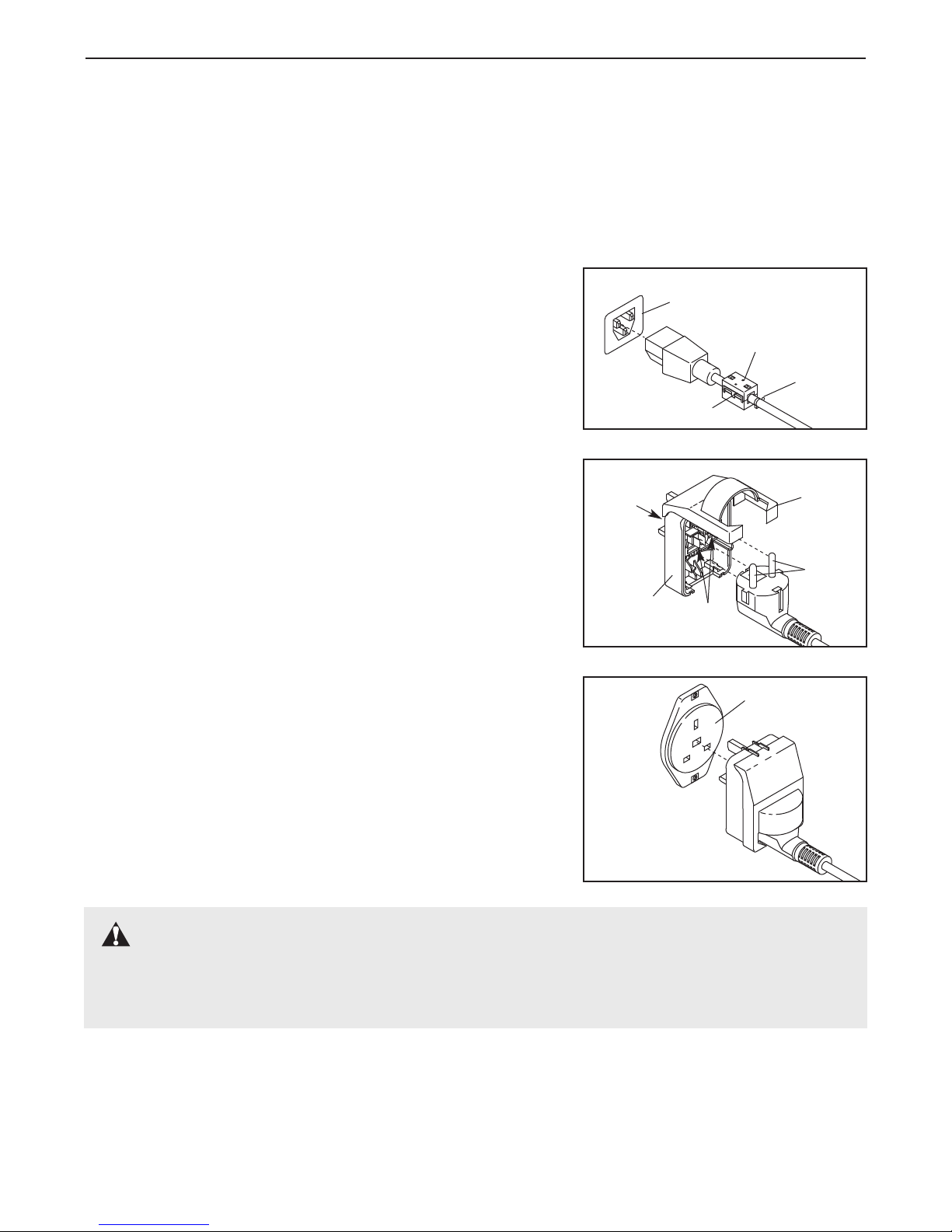
HOW TO PLUG IN THE POWER CORD
This product must be earthed. If it should malfunction or break
down, earthing provides a path of least resistance for electric current to reduce the risk of electric shock. This product is equipped
with a power cord having an equipment-earthing conductor and an
earthing plug.
be replaced with a manufacturer-recommended power cord.
See drawing 1. Plug the indicated end of the power cord into the
socket on the treadmill.
the ferrite box and clamp the ferrite box around the power cord.
Fasten the included plastic tie just behind the ferrite box and cut off
the excess plastic tie. The plastic tie will prevent the ferrite box from
sliding along the power cord.
See drawing 2. Press the pins on the power cord into the metal clips
in the Adaptor as shown. Close the Adaptor cover over the end of
the power cord and tighten the screw in the Adaptor. Important:
Make sure that the Adaptor cover is secure and the screw has
been tightened before using the power cord.
See drawing 3. Plug the power cord into an appropriate outlet that is
properly installed and earthed in accordance with all local codes and
ordinances. Important: The treadmill is not compatible with
GFCI-equipped outlets.
Important: If the power cord is damaged, it must
If a ferrite box is included, lift the tab on
1
2
Screw
Adaptor
3
Socket on treadmill
Ferrite
Box
Plastic
Tie
Tab
Adaptor
Cover
Pins
Metal
Clips
Outlet
DANGER: Improper connection of the equipment-earthing conductor can result in an in-
creased risk of electric shock. Check with a qualified electrician or serviceman if you are in doubt as
to whether the product is properly earthed. Do not modify the plug provided with the product—if it will
not fit the outlet, have a proper outlet installed by a qualified electrician.
1
1
 Loading...