

Page 1
PELSTARONE
External
Wireless Kit
USER INSTRUCTIONS
PELSTAR, LLC 9500 West 55th St. McCook, IL 60525-7110 USA www.homscales.com
P/N UMPELSTARONE_REV20181220
© Pelstar, LLC 2018
1
Page 2

Thank you for purchasing this Health o meter® Professional product. Please read this manual
carefully and keep it for easy reference or training.
TABLE OF CONTENTS
PRODUCT OVERVIEW................................................................................................................ 3
PACKAGE CONTENTS................................................................................................................ 4
HARDWARE INSTALLATION - STEP 1 ....................................................................................... 5
HARDWARE INSTALLATION - STEP 2 (FOR CONNEX MONITORS)............................................... 7
HARDWARE/DRIVER INSTALLATION STEP 2 (FOR COMMUNICATION TO WINDOWS
WIRELESS COMMUNICATION - STEP 3 ................................................................................. 12
TROUBLESHOOTING................................................................................................................ 13
WARRANTY ............................................................................................................................... 15
REGULATORY INFORMATION ................................................................................................. 16
®
PC) .......... 8
P/N UMPELSTARONE_REV20181220
2
Page 3

PRODUCT OVERVIEW
Intended Use
The hardware included with this kit allows a Health o meter® Professional scale to wirelessly transmit
data to a Windows® PC or a Welch Allyn
Transmitting Data to a Windows
To allow the scale to wirelessly transmit data to a Windows® PC, drivers for the included USB wireless
dongle must first be installed on the user’s PC. See page 8 for more information about setting up the
drivers on a PC. After installation, the USB wireless dongle must be inserted into a USB port on the PC.
Transmitting data into an EMR system requires that the user’s Windows® PC has one of the following
systems installed: Allscripts TouchWorks® or Professional™, Midmark® IQmanager® or ChARM Health
EHR.
Allscripts Interface: To complete the connection to Allscripts systems, users must download the
Allscripts app available at www.homscales.com/innovations/connectivity-solutions. Follow the
installation instructions included with the download. To complete installation, Allscripts must activate
the app within the user’s account to allow for interface between the scale and the Allscripts system
on the user’s PC.
Midmark Interface: Connection between the scale and Midmark IQ Manager requires that the
user’s PC has the IQ Manager software installed. For further information users must contact
Midmark Technical Support.
ChARM Health EHR Interface: ChARM Health users must contact their account manager to set up
the service.
Transmitting Data to a Welch Allyn® Connex
To allow the scale to wirelessly transmit data to a Welch Allyn® Connex® monitor, the included hardware
must be attached to the Welch Allyn® device. See page 7 for details about connecting the scale with
Welch Allyn® monitors. From the Welch Allyn® device, data can be transferred into an EMR. For data to
transfer to the EMR, the EMR installed on the user’s PC must be included on the list of Welch Allyn
EMR partners. Visit www.welchallyn.com to view a complete list of EMR partners. Health o meter®
Professional scales are preconfigured to interface with the following Welch Allyn® Connex® devices:
Connex® Spot Monitor, Connex® Vital Signs Monitors, Connex
Health o meter® Professional supports customers who wish to develop interfaces to their EMR and
other computer systems. Developers can obtain the communication protocols needed for the scale
models used in their particular environment at www.homscales.com/innovations/connectivity-solutions.
Windows
®
PC Requirements
This installation is exclusively compatible with Windows® XP/Vista/7
CPU of 1.7GHz and above
Minimum 512MB RAM
Available USB 2.0 Port
®
PC
®
device. See below for set up instructions.
®
Device
®
Integrated Wall Systems.
Cautions and Warnings
To prevent installation and performance issues to your PC, please follow these instructions
carefully.
For accurate data collection, confirm and upload the data according to the procedure
described in this manual.
Data validation must be confirmed by the user from the scale to the receiving device to
ensure accurate data collection.
P/N UMPELSTARONE_REV20181220
3
Page 4
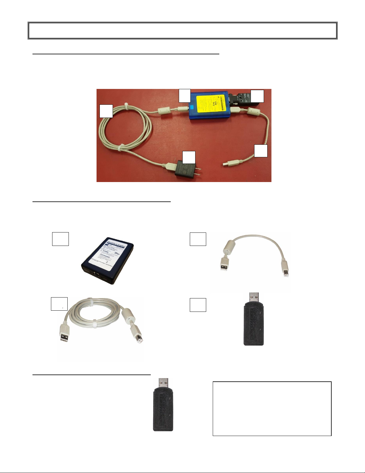
PACKAGE CONTENTS
1. HOMBT1 Scale Unit (Blue Box with Yellow Label)
2. RS232 Wireless Adapter
3. SCALE CABLE (1 ft. USB cable)
4. USB Wall Power Adapter
(Note: color of power adapter may vary)
5. POWER CABLE (6 ft. USB cable)
1. HOMWA Unit (Black Box with White Label)
2. USB Cable 1 ft.
3. USB Cable 6 ft.
4. USB Wireless Dongle
1
2
5
1
2
3
USB Wireless Dongle
3
4
4
Note: If connecting to a Windows® PC, the
HOMWA unit (black box with white label) will
not be used. The unused black box may be
returned to Health o meter® Professional
Scales. In return for unused black boxes, you
will receive a free ScaleSurance® extended
warranty for your scale. Call 1-800-815-6615
for more information.
Hardware to Connect to Health o meter® Professional Scale:
Hardware to Connect to Welch Allyn Device:
Hardware to Connect to Windows® PC
P/N UMPELSTARONE_REV20181220
4
Page 5

HARDWARE INSTALLATION - Step 1
TO SCALE
SCALE UNIT - Connected to scale
by adhesive label with Velcro®
POWER IN - Connected to USB
Wall Power Adapter
HOMBT1 Scale Unit
(Blue Box with Yellow Label)
Scale USB Port
Note: Color and shape
of the USB wall power
adapter may vary
1. Using the SCALE CABLE (1 ft. USB cable), connect the Health o meter® Professional scale USB
port to the “TO SCALE” USB port on the HOMBT1 Scale Unit as shown below.
2. Connect POWER CABLE (6 ft. USB cable) to USB Wall Power Adapter, and then connect other
end to the HOMBT1 Scale Unit “Power In” USB Port. (Note: This provides power to the HOMBT1
Scale Unit)
3. Connect the USB Wall Power Adapter to a wall power outlet as shown in the following figure. Or if a
Powered USB 2.0 Port or Powered USB 2.0 Hub is available, connect the USB cable directly to the
port/hub.
4. Utilizing the Velcro® adhesive, secure the HOMBT1 Scale Unit to the scale.
P/N UMPELSTARONE_REV20181220
5
Page 6

HARDWARE INSTALLATION - Step 2
The PELSTARONE External Wireless Kit allows for the scale to interface wirelessly with Welch Allyn
Connex® Spot Monitors, Connex® Vital Signs Monitors, and Connex® Integrated Wall Systems. Users
can also connect wirelessly to a Windows® PC to interface with Allscripts TouchWorks® or
Professional™, Midmark
To connect to Welch Allyn Connex® Vital Signs Devices, see page 7.
To connect to a Windows® PC, see pages 8-11.
®
IQmanager® or ChARM Health EHR.
P/N UMPELSTARONE_REV20181220
6
Page 7

HARDWARE INSTALLATION - Step 2 for Connex
HOMWA Unit Connection to
CVSM
1) Connect the 1 ft. USB cable to
any available USB port on the
Welch Allyn® CVSM
2) Connect the other end of the
1 ft. USB cable to the “TO
CONNEX DEVICE” USB port
on the HOMWA (black box)
Welch Allyn® CVSM
Connect the USB Wireless
Dongle to the “TO SCALE” USB
Port on the HOMWA unit
HOMWA Unit
(Black Box
with White Label)
The following instructions illustrate the hardware set up for connecting to a Welch Allyn® Connex®
Vital Signs Monitor (CVSM). USB ports on the Connex Spot and Integrated Wall Systems are
located on the underside of the monitor.
®
Monitors
1. Connect the USB Wireless Dongle to the HOMWA unit as the following figure.
2. Connect the HOMWA (black box) with dongle to the Welch Allyn
3. Power on the Welch Allyn
communication. The connection is now established.
4. To enable weight scale communication on the Welch Allyn
a) Connect the CVSM to a PC to access the Welch Allyn® Service Tool. This service tool either
comes with the Welch Allyn® device or can be downloaded at
www.welchallyn.com/en/service-support/service-center/service-tool.html.
P/N UMPELSTARONE_REV20181220
b) Follow the prompts in the Service Tool to activate the weight scale license.
c) Activate the license by entering the authorization code A66FF29A3B2F85E1
Continue to page 12 for Step 3 - Wireless Communication instructions.
Note: The set up presumes that the HOMBT1 Scale Unit is attached to the scale, see Step 1 on
page 5.
®
CVSM as shown below.
®
CVSM unit and power on the scale to initialize wireless
®
CVSM, follow these steps.
7
Page 8

HARDWARE/DRIVER INSTALLATION (for Scale Communication
to a Windows® PC)
1. Download the CP210x USB to UART Bridge VCP Driver using one of the following
methods:
a. Go to http://www.silabs.com/products/mcu/pages/usbtouartbridgevcpdrivers.aspx
b. Go to http://www.silabs.com/ and search for “CP2102 Driver Download”.
2. Select the download for Windows® XP/Server 2003/Vista/7/8/8.1/10 (6.7) – Version 6.7
or the latest version available.
3. Unzip the downloaded file if necessary.
The following example shows installation for a Windows 64 bit OS.
Follow the installation wizard steps. Click the “Next” button.
P/N UMPELSTARONE_REV20181220
8
Page 9

HARDWARE/DRIVER INSTALLATION (for Scale Communication
to a Windows® PC) – (Cont.)
Accept the license agreement and click “Next”
Please wait while the driver installs.
P/N UMPELSTARONE_REV20181220
9
Page 10

HARDWARE/DRIVER INSTALLATION (for Scale Communication
to a Windows® PC) – (Cont.)
When driver installation is complete click “Finish” to close the installation Wizard.
4. Connect the USB wireless dongle to any available USB 2.0 port on the Windows® PC.
P/N UMPELSTARONE_REV20181220
10
Page 11

Hardware/Driver Installation (for Scale Communication to a
Windows® PC) – (Cont.)
5. Open Windows® “Device Manager” and check that the USB wireless dongle was
recognized by the Windows® OS.
6. Once the driver installation is complete, the USB wireless dongle will automatically
connect to the scale and will be ready to receive data.
7. The driver installation is now ready to communicate with applications on the PC. Power
on the scale to initialize wireless communication.
Note: Transmitting data into an EMR system on the PC requires that the user’s
Windows® PC has one of the following systems installed: Allscripts TouchWorks,
Allscripts Professional, Midmark IQ Manager Software, or ChARM Health EHR. See the
Product Overview section on page 3 for more information.
Continue to page 12 for Step 3 - Wireless Communication instructions.
Note: The set up presumes that the HOMBT1 Scale Unit is attached to the scale, see Step 1 on
page 5.
P/N UMPELSTARONE_REV20181220
11
Page 12

WIRELESS COMMUNICATION - Step 3
Wireless Status LED
Solid Blue = Active
Communication
Blinking Blue = NO
Communication
Power LED
Solid Red = Active Power
Blinking Red = Power
Supply Low*
Off = No Power*
SERIAL NUMBERS MUST MATCH
TO ENABLE WIRELESS
COMMUNICATION.
HOMBT1 SCALE UNIT
USB WIRELESS DONGLE
NOTE: THE SERIAL NUMBER ON THE USB WIRELESS DONGLE MUST MATCH THE
SERIAL NUMBER ON THE YELLOW LABEL OF THE HOMBT1 SCALE UNIT TO
ENABLE ACTIVE WIRELESS COMMUNICATION.
1. Power on the scale and either the Welch Allyn monitor or PC. To check that the HOMBT1 scale
unit has established wireless communication, observe that the status LEDs are illuminated as in
the figure below.
Note: When attached to the scale you will be viewing the device upside down.
P/N UMPELSTARONE_REV20181220
12
Page 13

TROUBLESHOOTING
LED Indicators
LED Color
Status
Description
Power
Red
On
Power On
Off
Power Off/ Device Error
Blinking
Power Supply Low
Status
Blue
On
Active Communication
Blinking
No Communication
Status LED
Blue LED
Status LED
Red LED
SERIAL NUMBERS MUST MATCH
TO ENABLE WIRELESS
COMMUNICATION.
HOMBT1 SCALE UNIT
USB WIRELESS DONGLE
NOTE: THE SERIAL NUMBER ON THE USB WIRELESS DONGLE MUST MATCH THE
SERIAL NUMBER ON THE YELLOW LABEL OF THE HOMBT1 SCALE UNIT TO
ENABLE ACTIVE WIRELESS COMMUNICATION.
RS232 Wireless Adapter LED Indicators
Note: When attached to scale you will be viewing the device upside down.
P/N UMPELSTARONE_REV20181220
13
Page 14

TROUBLESHOOTING (Cont.)
Problem
Possible Cause
Suggested Action
No Power
Check USB/Battery – DB9-
Pin 9(5V) switch position
Check that switch is set to DB9-Pin9(5V)
position setting
No
Communication
Check DCE(F)/DTE switch
position
Check that switch is set to DTE position
setting
Serial number on Wireless
Dongle does not match Serial
Number on HOMBT1 Scale
Unit
Check that the Serial Number on yellow
label of HOMBT1 Scale Unit matches the
Serial Number on the USB wireless
dongle. If they do not match contact
Health o meter Professional Customer
Service at 1-800-815-6615.
RS232 Wireless Adapter out of
communication range
Check that the distance between the
scale and the Connex® device or PC is
less than ~328ft (100m)
Wireless network interference
Move the scale or Connex® device away
from other wireless devices nearby
Wireless connection
Re-cycle power to the HOMBT1 Scale
Unit by disconnecting the USB cable
connected to “POWER IN” and
re-connect
Problem
Possible Cause
Suggested Action
No Power/USB
Power failure or USB error
failure
Re-cycle power to the HOMWA by
disconnecting the USB cable connected
to “TO CONNEX DEVICE” and re-
connecting
No
Communication
USB Wireless Dongle out of
communication range
Check that the distance between the
scale and Connex® device or PC is less
than ~328ft (100m)
Serial Number on USB Wireless
Dongle does not match Serial
Number on HOMBT1 Scale Unit
Check that the Serial Number on yellow
label of HOMBT1 Scale Unit matches the
Serial Number on the USB Wireless Dongle.
If they do not match contact Health o meter
Professional Customer Service at 1-800-
815-6615.
Wireless network interference
Move scale or Connex® device away
from other wireless devices nearby
HOMWA to Connex® Device
Re-cycle power to the HOMWA by
disconnecting the USB cable connected
to “TO CONNEX DEVICE” and re-
connecting
USB Wireless Dongle to
Windows® PC
Check that the Virtual Comport CP210x
Driver Installation is installed properly
via Windows® Device Manager. Re-
install driver if necessary
RS232 Wireless Adapter Fault Symptoms
USB Wireless Dongle Fault Symptoms
P/N UMPELSTARONE_REV20181220
14
Page 15

LIMITED WARRANTY
IN NO EVENT SHALL THE VENDOR'S LIABILITY FOR DIRECT, INDIRECT, SPECIAL,
INCIDENTAL OR CONSEQUENTIAL DAMAGES RESULTING FROM THE USE OF THE
PRODUCT, DISK, OR ITS DOCUMENTATION EXCEED THE PRICE PAID FOR THE
PRODUCT.
The vendor makes no warranty or representation, expresses, implied, or statutory with respect to the
contents or use of this documentation, and especially disclaims its quality, performance,
merchantability, or fitness for any particular purpose. The vendor also reserves the right to revise or
update the device or documentation without obligation to notify any individual or entity of such
revisions, or updates.
What does the Warranty Cover?
This Health o meter® Professional product is warranted from date of purchase against defects of materials or in workmanship for a period
of one (1) year. If the manufacturer determines that a defect of material or in workmanship exists, the customer’s sole remed y will be
replacement of the product at no charge. Replacement will be made with a new or remanufactured product or component. If the product is
no longer available, replacement may be made with a similar product of equal or greater value. All replaced parts are covered only for the
original warranty period.
Who is Covered?
The original purchaser of the product must have proof of purchase to receive warranty service. Please save your invoice or receipt. Pelstar
dealers or retail stores selling Pelstar products do not have the right to alter, or modify or in any way change the terms and conditions of
this warranty.
What is Excluded?
Your warranty does not cover normal wear of parts or damage resulting from any of the following: negligent use or misuse of the
product, use on improper voltage or current, use contrary to the operating instructions, abuse including tampering, damage in transit, or
unauthorized repair or alternations. Further, the warranty does not cover natural disasters, such as fire, flood, hurricanes and tornadoes. This
warranty gives you specific legal rights, and you may also have other rights that vary from country to country, state to state, province to
province or jurisdiction to jurisdiction.
To get Warranty Service make sure you keep your sales receipt or document showing proof of purchase. Call (+1) 800-638-3722 or
(+1) 708-377-0600 to obtain a replacement product.
PELSTAR, LLC
9500 West 55th Street • McCook, IL 60525 • USA
1-800-815-6615 or 1-708-377-0600
Health o meter® is a registered trademark of Sunbeam Products, Inc. used under license.
Health o meter® Professional products are manufactured, designed, and owned by Pelstar, LLC.
We reserve the right to improve, enhance, or modify Health o meter® Professional product features or specifications without notice.
© Pelstar, LLC 2018
P/N UMPELSTARONE_REV20181220
15
Page 16

REGULATORY INFORMATION
FCC ID: XJ8-BT 232B
CCAB09LP2610T2
CE1177
RS232 Wireless Adapter
RADIO FREQUENCY INTERFERENCE STATEMENT
This equipment has been tested and found to comply with the limits for a Class B digital device, pursuant to Part 15 of the
FCC rules. These limits are designed to provide reasonable protection against harmful interference in a residential
installation. This equipment generates, uses and can radiate radio frequency energy and if not installed and used in
accordance with the instructions, may cause harmful interference to radio communications. However, there is no guarantee
that interference will not occur in a particular installation. If this equipment does cause harmful interference to radio or
television reception, which can be determined by turning the equipment off and on, the user is encouraged to try correcting
the interference by one or more of the following measures:
- Reorient the receiving antenna.
- Increase the separation between the equipment and receiver.
- Connect the equipment into and outlet on a circuit different from that to which the receiver is connected.
- Consult the dealer or an experienced radio/TV technician for help.
Warning: A shielded-type power cord is required in order to meet FCC emission limits and also to prevent interference to
the nearby radio and television reception. It is essential that only the supplied power cord be used.
You are cautioned that changes or modifications not expressly approved by the party responsible for compliance could void
your authority to operate the equipment.
Declaration:
1. The information contained in this document is subject to change without notice.
P/N UMPELSTARONE_REV20181220
16
Page 17

REGULATORY INFORMATION (Cont.)
USB Wireless Dongle
RADIO FREQUENCY INTERFERENCE STATEMENT
This module has been tested and found to comply with the FCC part 15 and IC RSS-210 rules. These limits are designed to
provide reasonable protection against harmful interference in approved installations. This equipment generates, uses, and can
radiate radio frequency energy and, if not installed and used in accordance with the instructions, may cause harmful
interference to radio communications. However, there is no guarantee that interference may not occur in a particular
installation. This device complies with part 15 of the FCC rules. Operation is subject to the following two conditions: (1) this
device may not cause harmful interference, and (2) this device must accept any interference received, including interference
that may cause undesired operation.
Modifications or changes to this equipment not expressly approved by the part responsible for compliance may render void
the user’s authority to operate this equipment.
Modular Approval, FCC and IC
FCC ID: X3ZBTMOD3
IC: 8828A-MOD3
In accordance with FCC part 15, the SPT2632C1A.AT2 is listed above as a modular transmitter device.
CE Certification
USB dongle has been certified according to following certification rules:
– CE Expert opinion: 0447-ARSO00093-r
– Measurements have been performed in accordance with (report available on request):
– EN 300 328 V 1.8.1 (2012:06) (a)
– EN 301 489-17 V 2.2.1 (2012:09) (b)
– EN 301 489-1 V1.9.2 (2011:09) (c)
– EN60950-1:2006 +A12:2011 (d)
-CE certified:
P/N UMPELSTARONE_REV20181220
17
 Loading...