

Page 1

PROPLUS
®
2101 SERIES
USER INSTRUCTIONS
INSTRUCCIÓNES DE USO
MODE D'EMPLOI
Patents D523367, 7550682B2 and D508655 (US); Patents Pending and 0149984/1-8 (EU);
Patents 806658, 879866, ZL200480031711X and 200430004551.2 (PRC) © Pelstar, LLC 2010
Rev. 20100621
0470
Page 2

2101 Series
Thank you for your purchase of this Health o meter® Professional product.
Please read this manual carefully and keep it for easy reference or training.
Gracias por su compra de éste producto Health o meter® Profesional. Lea éstas instrucciónes
con cuidado, y mantenga el manual disponible para futuras consultas y también para su uso a la
hora de orientar o formar al nuevo personal que la utilizará.
Merci d’avoir acheté ce produit Health o meter® Professionnelle. Veuillez lire attentivement ce
manuel et le garder à portée de main pour pouvoir le consulter à tout moment.
TABLE OF CONTENTS
ENGLISH..................................................................................................................1
ESPAÑOL ................................................................................................................13
FRANÇAIS ...............................................................................................................26
DIGITAL BARIATRIC SCALE WITH HANDRAILS
USER INSTRUCTIONS
CAUTION AND WARNING................................................................................................. 2
SPECIFICATIONS FOR THIS SCALE................................................................................ 2
CERTIFICATIONS / CONNECTIVITY / DISPOSAL ............................................................ 3
ASSEMBLY INSTRUCTIONS............................................................................................. 4
SET UP / BATTERIES........................................................................................................ 5
QUICK START INSTRUCTIONS ........................................................................................ 6
MAINTENANCE / CALIBRATION ....................................................................................... 8
TROUBLESHOOTING........................................................................................................ 9
DETAILED VIEW OF SCALE ............................................................................................. 10
PARTS FOR MAINTENANCE............................................................................................. 11
WARRANTY ....................................................................................................................... 12
PLEASE REGISTER YOUR SCALE FOR WARRANTY COVERAGE AT:
http://www.homscales.com/customers/registration.aspx
POR FAVOR REGÍSTRE SU BÁSCULA PARA OBTENER COBERTURA
DE LA GARANTIA EN:
http://www.homscales.com/customers/registration.aspx
MERCI D'ENREGISTRER LA BALANCE AFIN DE LA GARANTIE SUR LE:
http://www.homscales.com/customers/registration.aspx
Page 3

CAUTION AND WARNING
To prevent injury and damage to your scale, please follow these instructions very carefully.
• Do not transport the scale while the platform is loaded.
• For accurate weighing the scale must be placed on a flat, stable surface.
• For accurate weighing, verify proper operation according to the procedure described in this
manual before each use.
• Do not use in the presence of flammable materials.
• Operating at other voltages and frequencies than specified could damage the equipment.
• If the “LOW BAT” indicator activates, for accurate weighing, replace the batteries or connect
the scale to a power source, using the power adapter, as soon as possible.
SPECIFICATIONS FOR THIS SCALE
GENERAL
The ProPlus® 2101Series Digital Handrail Scale uses highly sophisticated microprocessor
technology. Each precision scale is designed to provide accurate, reliable and repeatable weight
measurements and features that make the weighing process simple, fast and convenient.
This scale is set up to use motion-sensing weighing technology, to determine the actual weight
of a moving patient. The scale may be changed to measure live weight (see the ProPlus®
Display Module User Manual for instructions on how to change the scale settings).
Weight can be displayed in pounds (decimals, fractions of a lb, lb/oz) or in kilograms. The
scale features a wrap-around handrail for patient comfort and safety. It also has a 180° swivel
display head for privacy and easy operator reading from either side of the scale. It has two
wheels built in for easy mobility. The unit can be operated using its power adapter (included) or
by 6-D cell batteries (not included).
2101 SERIES SPECIFICATIONS
Capacity and
Resolution
Power Requirements
Environmental
2101KL: 1000 lb x 0.2 lb / ¼ lb / 4 oz (454 kg x 0.1 kg)
2101KG: Max 400kg / Min 1kg, e=0.1kg (Class III)
120V-240V AC, 50-60Hz - 9V DC adapter or 6 D-cell batteries
Operating temperatures: 50°F to 95°F (10°C to 35°C)
Storage temperatures: 30°F to 125°F (0°C to 50°C)
Maximum Humidity: 85% RH
Physical Dimensions Platform
Length: 22” (56 cm)
Width: 26” (66 cm)
Height: 2-¼” (5.7 cm)
Assembled Product Size and Weight
Length: 30” (76 cm)
Width: 27-¾” (70.5 cm)
Height: 49-2/5” (125 cm)
Weight: 72 lb (32.5 kg)
Page 4

CERTIFICATIONS / CONNECTIVITY / DISPOSAL
CERTIFICATION DESCRIPTIONS
cales carrying this symbol meet the Precision Class III standards
S
of the Directive 90/384 EEC
2101 SERIES SCALE CONNECTIVITY INFORMATION
This scale is designed to connect to a computer, monitor or other devices via USB or serial
ports, to allow reliable transmission of weight, height and BMI from the scale. This
connectivity helps close a source of potential medical errors caused by incorrectly copying
and then recording weight information taken. This scale is EMR-EHR compatible. For more
information regarding how to connect this scale to devices please request Health o meter®
Professional Scale Technical Support (available normal business days) at (+1) 800-815-6615
or (+1) 708-377-0600.
2101 SERIES SCALE DISPOSAL
Products carrying this symbol meet the requirements of:
1. Directive for non-automatic weighing instruments 90/384/EEC
2. Directive governing medical devices 93/42/EEC
Pelstar, LLC has been officially certified as a manufacture of Health
o meter® Professional medical devices to be in compliance with
stringent legal requirements. The Pelstar, LLC quality assurance
system covers the development, production, sales and service of
medical scales and measuring systems.
Do not dispose of this device in domestic waste. This Health o meter® Professional scale
must be disposed of properly as electronic waste. Follow the national, regional or local
regulations which apply to you for disposal.
Page 5

5
ASSEMBLY INSTRUCTIONS
Before Assembly:
The ProPlus® 2101Series Digital Handrail Scale is shipped disassembled in one carton. Carefully inspect the carton for
shipping damage before unpacking. If damage is found, contact your shipper or Health o meter® Professional representative
immediately. Claims must be filed with the shipper as soon as possible after receipt of the package, if there are damages. The
following information details what you will find inside the main carton, as you unpack the parts for assembly.
Remove each
carton aside, for storage. To avoid damaging the scale parts when unpacking it, do not use a box cutter, knife, scissors or
any sharp object to open the protective inner packaging.
assembly from the carton and unwrap packing material carefully, to prevent scratching the unit’s parts. Set the
Parts List:
(1) Base (Platform) Assembly The Small, Long Box Contains:
(1) Center Handrail (1) Box Containing the Power Adapter
(2) Side Handrails (4) Feet
(1) Handle (1) Rear Cover for Display
(1) User information (1) Adapter Holder
(1) Box Containing: (3) Allen Wrenches—small, medium, large
(1) Display Assembly (1) Plastic Bag Containing:
(1) Small, Long Box (1) Front Cover for Display Support
(1) Small Rear Cover for Display Support
Hardware for Assembly (Figure 1)
Tools required: Phillips head screwdrivers (not included), Allen wrenches (included).
IMPORTANT
A detailed view of the scale is illustrated on page 10.
: Please refer to the maintenance parts list on page 11 for more details about each part.
Figure 1
Assembling a 2101 Series Scale:
It is recommended that the assembly be done by two people.
1. Place scale base on a flat, level, dry floor.
2. Locate and pick up the center handrail, then find the load cell cable, untie it and pull it out the bottom.
3. Position the handrail over the platform and feed the cable through the handrail support in the base, being sure not
to pinch the cable.
4. Slide the center handrail over the handrail supports on the base and fasten the handrail to the handrail supports
using four (4) M8 1.25 x ¾ screws (B), four (4) M8 washers (F) and the medium Allen wrench (see Figure 1).
Lightly tighten the screws. DO NOT OVERTIGHTEN. Wait to tighten until Step 6.
5. Attach the left / right side handrails to the center handrail and platform using the two (2) M10 1.5 x 1½ screws (A),
eight (8) M8 1.25 x ¾ screws (B) with eight (8) M8 washers (F), and lightly tighten.
6. Starting at the top and working down the sides and base, fully tighten all 14 screws in the handrails.
7. Attach the handle to the back of the center handrail using two (2) medium M6 1.0 x ½ screws (C), and tighten.
8. Pull forward on the side handrails to tip the scale and gently place it face down on the floor.
9. Grasp the load cell cable protruding from the bottom of the base and feed it through the protective metal shield
above the wheel in the base of the scale, then plug it into the load cell port in the center of the base.
10. Pull the excess cable through the top of the scale.
11. Thread the 4 feet into the underside of the base. Each foot should be completely hand tightened and then backed
out 1-½ full turns. This allows for proper load cell operation for accuracy of the scale.
12. Carefully tilt the scale back to an upright position on the floor. DO NOT DROP THE SCALE. Adjust the feet, to
level the scale. Be certain that the feet are NOT completely tightened into the base (see Step 11, above).
-
Page 6

ASSEMBLY INSTRUCTIONS (CONTINUED)
Assembling a 2101 Series Scale (continued):
Figure 2
1
3. Rotate the display support 90˚ then position the Display Assembly close to the Display Support. Plug the
load cell cable connector into the load cell port on the rear of the Display then insert and secure the cable
into the center channel in the display. See Figure 2, above, for an illustration. Note
power cord at this point. Wait until Step 19.
14. Slide the display assembly onto the metal display support insuring that the two metal tabs go into the two
slots in the rear of the display. Note
: The load cell cable should now be secured in the channel
between the display assembly and the display support.
15. Insert four (4) Phillips pan head M4 screws (E) into the metal display support, and tighten (see Figure 1).
16. Attach the Adapter Holder to the center rail using two (2) #8 x ½ (D) sheet metal screws, and tighten.
17. Connect the power adapter to the power port in the display, then insert and secure the cable into the exposed
portion of the second channel from the left in the back of the display (see Figure 2, above). Hold the cord in
place through the retaining slot on the rear cover and align the large rear cover tabs with the slots on the rear
of the display assembly. Apply light pressure to snap the cover into place and secure it with two (2) Phillips
pan head M4 screws (E). Do not plug the scale into a power source until the scale is fully assembled.
18. Rotate the display to align it with the center handrail then attach the front and small rear display support
covers, applying light pressure to snap these covers into place.
19. Secure the power cord to the inside of the center handrail, using the 4 plastic cable clips, arranged to hold
the cord out of the way. The adhesive backing on the clips will peel off then the clips can be fastened to the
scale by applying light pressure.
20. The scale is now assembled. Plug the scale adapter into a power source and / or insert batteries.
: Do not attach the
SET UP
ProPlus® 2101Series scales are shipped with the Menu Lock function enabled. The Menu Lock function
disables certain buttons on the scale’s keypad, preventing unauthorized users from making changes to
your scale settings. The Menu Lock can be bypassed temporarily to allow you to customize your scale
with the functionality you prefer. Please refer to the ProPlus® Display Module User Manual for
instructions on how to bypass the Menu Lock.
Preparing the Scale for Use
1. Remove protective plastic films covering the keypad and display.
2. Place batteries in the battery holder (see “Batteries” information in Figure 3, below).
3. Plug the scale’s power adapter into the power source.
4. Be sure all objects are removed from the scale’s platform, and then press the ON/OFF button to turn the
scale on. The display will show “Health o meter ProPlus” and then “000Lb00oz” or “0.0KG”. Note
: To adjust
the display backlight and/or contrast, please refer to the ProPlus® Display Module User Manual.
5. Press the KG/LB button to select the weight mode (pounds or kilos). To change the display mode in pounds
to fractions or decimals, please refer to the ProPlus® Display Module User Manual.
Note
: The scale will always default to the settings and units last used (LB or KG).
6. When you disconnect the scale’s power adapter from the power source, the scale will switch to battery
power, if batteries are installed. Note
: If the set up procedure failed, refer to the troubleshooting instructions.
If the problem is not corrected, refer to qualified service personnel.
Page 7

SET UP / BATTERIES
Replacing / Inserting Batteries
Figure 3 - Batteries
1. Unplug the scale.
2. Remove the battery cover from the display assembly—refer to Figure 3 (A) above.
3. Disconnect battery holder cable connector from the scale-battery connector (B).
4. Carefully remove the battery holder (C) by sliding it out of the display assembly.
5. Replace the batteries with new ones. We recommend EVEREADY Energizer
6. Carefully slide the battery holder (C) into the display assembly.
7. Plug the battery holder cable connector to the scale-battery connector (B).
8. Attach the battery cover to the display assembly and install the screw (A).
®
e2TM batteries.
Warning
: If the scale will not be used for some time, remove batteries to avoid a safety hazard.
QUICK START INSTRUCTIONS
NOTE: This scale will always default to the settings and units last used (lb or kg), when it is turned on.
1. Make sure there is no object on the weighing platform.
2. Press the ON/OFF button to turn the scale on.
3. Wait until ”0LB 0OZ” or “0.0Kg” and “ZERO” on the left side of the display appear.
4. Ask the patient to step on the scale. The scale will calculate the patient’s weight but the display will
not show a weight until the stable weight of the person is determined. Depending on the
movement of the patient on the scale, it may take several seconds for the scale to lock onto the
weight.
5. Once a weight has been displayed, while the patient is still on the scale, we recommend
performing a second weighing by pressing the REWEIGH button.
6. After the weight measurement has been taken and is recorded ask the patient to step off the scale.
7. Press the ON / OFF button to turn the scale off.
Body Mass Index is another name for Quetelet Index, a formula that is a convenient and reliable
indicator of obesity. NOTE
: The scale will not calculate BMI for a patient that is 24 pounds (12 kg) or
less. If a height is not entered for the patient within 30 seconds of pressing the BMI button, the scale
will return to the normal weighing mode.
1. Complete steps 1 to 4 above for “Weighing A Patient”.
2. After obtaining the patient’s weight on the scale, press the BMI (2) button while the scale is on.
3. The scale will prompt you to enter the patient’s height. Use the keypad to enter the height.
: When weighing in pounds, the height is entered in ¼” increments. To increase the fractional
NOTE
height of the patient, press “1” for ¼”, “2” for ½” and “3” for ¾”. When weighing in kilograms, the height
must be entered in 0.1 centimeter increments.
WEIGHING A PATIENT
CALCULATING BMI
Page 8

QUICK START INSTRUCTIONS (CONTINUED)
4. Once height is keyed in, press ENTER.
5. The display will show the patient’s BMI (Body Mass Index).
6. Press EXIT to return to the normal weighing mode of the scale.
When using the scale, the weight of an object such as shoes accompanying the patient can be subtracted
from the total weight to determine the weight of the patient alone. The Tare Function automatically
performs this subtraction. ProPlus® scales allow tare weight to be entered manually by using the keypad
or automatically, as outlined in this section.
AUTOMATIC (PUSH BUTTON TARE)
1. With all weight off the scale, press the ON/OFF button to turn on the scale.
2. Wait until ”0LB 0OZ” or “0.0Kg” and “ZERO” appear on the left side of the display.
3. Put the weight to be tared on the scale. The display will show a value for that weight.
4. Press the TARE (9) button. The scale will zero out and the word “TARE” will appear in the upper right
side of the display to indicate there is a tare value for this patient.
5. Remove the weight from the scale. The display will show a negative weight equal to the weight of the
shoes or other item, once that item is removed from the scale.
6. Place the patient and the tared object on the scale. The scale will automatically deduct the tared
weight, as entered, from the gross weight of the patient and tared object.
7. The weight of the patient will appear on the scale.
8. The tared value is stored in memory until changed, cleared or the scale is turned off.
9. To remove the Tare, press the TARE (9) button again. The word “TARE” will disappear from the display
and the tare value will be deleted from memory. The scale will resume normal operation.
MANUAL (KEYBOARD OR KEYPAD TARE)
1. Make sure there is no object on the weighing platform.
2. Press the ON / OFF button to turn on the scale.
3. Wait until ”0LB 0OZ” or “0.0Kg” and “ZERO” appear on the left side of the display.
4. Press the TARE (9) button. The user will be prompted to enter the tare value.
5. Use the keypad to enter the weight of the shoes or other object and then press ENTER.
6. The value entered will show as a negative value on the display.
7. Place the patient and the tared object on the scale. The scale will automatically deduct the tared
weight, as entered, from the gross weight of the patient and tared object.
8. The weight of the patient will appear on the scale.
9. The tared value is stored in memory until changed, cleared or the scale is turned off.
10. To remove the Tare, press the TARE (9) button again or EXIT. The word “TARE” will disappear from
the display and the tare value will be deleted from memory. The scale will resume normal operation.
REMOVING THE TARE VALUE
Press the TARE (9) button again to delete a tare value from memory. The word “TARE” will disappear
from the display and the tare value will be deleted from memory. You can also press the EXIT button. The
scale will resume normal operation.
CALCULATING BMI (CONTINUED)
TARE FUNCTION
Additional, complete instructions regarding all of the display and keypad functions and
menus can be found in the ProPlus® Display Module User Manual included with this scale.
Page 9

MAINTENANCE
The following pages provide instructions for maintenance, cleaning, troubleshooting and
operator replaceable parts for the ProPlus
those described in this manual should be performed by qualified service personnel.
®
2101 Series. Maintenance operations other than
MAINTENANCE
Before first use and after periods of non-use, check the scale for proper operation and
function. If the scale does not operate correctly, refer to qualified service personnel.
1. Check overall appearance of the total scale for any obvious damage, wear and tear.
2. Inspect the power adapter for cord cracking or fraying or for broken or bent prongs.
CLEANING
Proper care and cleaning is essential to ensure a long life of accurate and effective operation.
Disconnect the scale from the adapter power source.
1. Clean all external surfaces with a clean damp cloth or tissue. Mild antimicrobial or
antibacterial soap and water solution may be used. Dry with a clean soft cloth.
2. Do not immerse the scale into cleaning or other liquid solution.
3. Do not use Isopropyl Alcohol or other solutions to clean the display surface.
4. Do not use abrasive cleaners.
2101 SERIES CALIBRATION
This scale has been factory calibrated and does not require calibration prior to use. For
maintenance, the scale can be calibrated. Calibration of your ProPlus® scale is performed using kilos
(kg) or pounds (lb), according to the units of measure used upon entering into the calibration path.
Operator Action Display
1. Make sure the display is turned off, then press and hold the
HOLD/RELEASE button while pressing the ON/OFF button.
2. Using the cd keys and/or the numeric keypad, set the calibration
load to at least half the capacity of the scale (for the best results
and greater accuracy, use the full capacity of the scale.
3. Make sure there is nothing on the scale, then press the
ENTER button.
4. Please wait 1-3 seconds, without touching or shaking the
scale, to allow the Zero Calibration to finish.
5. No action required by operator. Weight calibration:
6. Load the scale with the required weight and press the ENTER
button. Please wait 1-3 seconds, without touching or shaking
the scale, to allow the Calibration to finish.
7. If calibration is successful, the display will show “Factor OK!”.
If the calibration process failed, it will show “Factor Fail!”.
8. If successful, the display will begin to reboot. Rebooting…
9. The display will return to the start up message. Health o meter
10. Please wait until the scale resumes normal operation and
then remove the weight from the scale.
“Enter load weight:
400.0LB “
or “200.0KG”
“Enter load weight:
400.0LB “
or “200.0KG”
Zero calibration:
Please clear the scale
Zero calibration:
Please wait
Put: XXX.X
Weight calibration
Please wait
Factor Update…
“Factor OK!”
or “Factor Fail!”
Please wait
ProPlus
Health o meter
ProPlus
Page 10

TROUBLESHOOTING
Refer to the following instructions to check and correct any failure before contacting service personnel.
SYMPTOM POSSIBLE CAUSE CORRECTIVE ACTION
Scale does not turn on 1. Dead Battery
2. Faulty electrical outlet
3. Bad power supply
Questionable weight or
the scale does not zero
2. The display did not show
3. Scale is not placed on a
4. Scale is out of
5. Improper Tare 5. Place the item to be tared
1. External object
interfering with the scale
”0.0” before weighing
level floor
calibration
1. Replace batteries
2. Use a different outlet
3. Replace adapter
1. Remove interfering object
from the scale
2. Ask the patient to get off
the scale, zero the scale
and begin weighing
process again
3. Place the scale on a level
floor and begin weighing
process again
4. Check weight with known
weight value
on the scale. Press
REWEIGH. Once the
weight of the item is
displayed, press TARE.
Place the patient and the
tared item back on the
scale. Press REWEIGH
again
Weighing is performed but
the display shows “weigh”
and “reweigh” every few
seconds; the weighing
process takes too long and
no weight is displayed.
The display shows
“Overload” message
The display shows
“LOW BAT” message
The display shows
“Load Cell Error” message
The patient is not standing
still
The load on the scale
exceeds the capacity
(1000 lb / 400 kg)
The batteries are empty Replace batteries according to
There is a problem with one
or more load cells or the load
cell cable is disconnected.
Ask the patient to stand still or
you can change to live weight
setting
Remove the excess weight and
use the scale according to its
limits
instructions
Check load cell cable
connection at the display and
platform assembly ports. If the
problem is not corrected, refer
to qualified service personnel
to replace the defective load
cell
Page 11
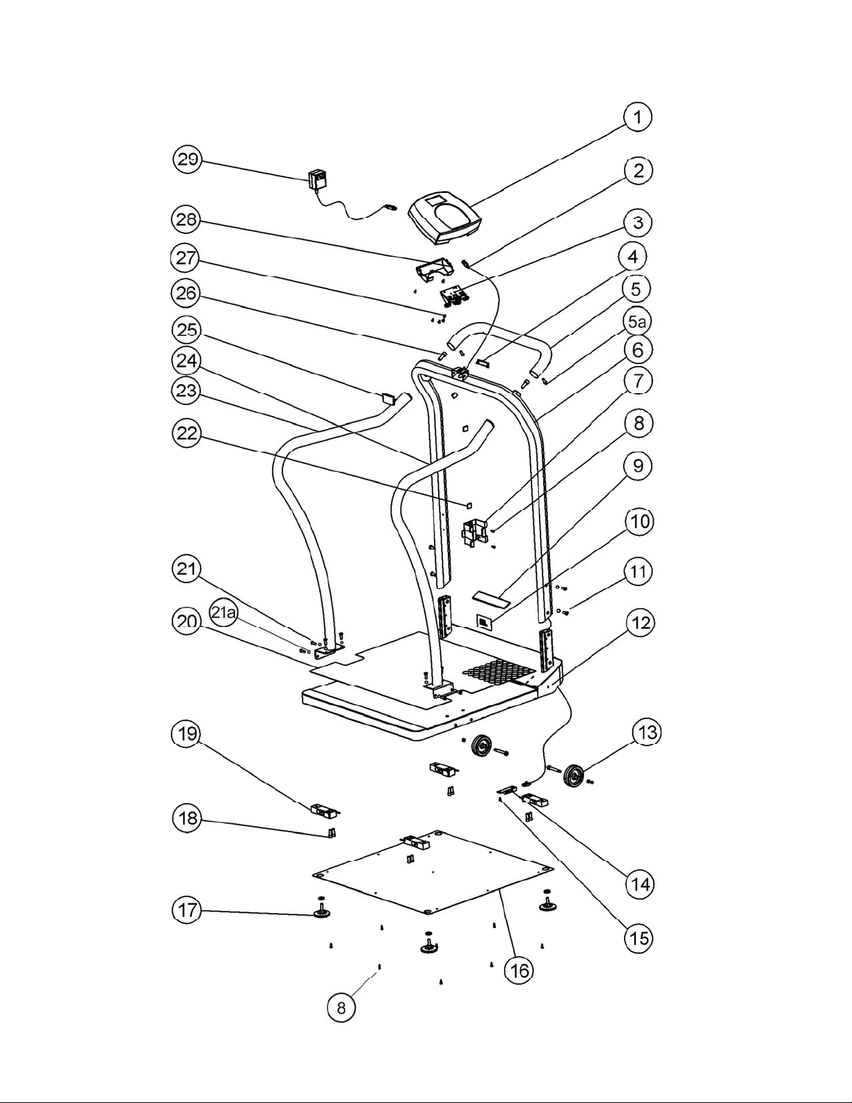
DETAILED VIEW OF 2101 SERIES SCALE
VISTA DETALLADA DE LA BÁSCULA SERIE 2101
ÉCLATÉ DE LA BALANCE SÉRIE 2101
Page 12

2101 SERIES PARTS FOR MAINTENANCE
Key
Part No. Description Qty.
No.*
1 B1109401-0 DISPLAY ASSEMBLY 1
2 B2033701-0 MAIN BOARD TO JUNCTION BOX LOAD CELL CABLE 1
3 B2266901-0 DISPLAY SUPPORT 1
4 B3822601-0 SMALL REAR COVER FOR DISPLAY SUPPORT 1
5 B3822901-0 HANDLE 1
5a SOCKET HEAD CAP SCREW M6 1.0 x ½ 2
6 B3822101-0 HANDRAIL 1
7 B3817001-0 ADAPTER HOLDER 1
8 SHEET METAL SCREW #8 x ½ 11
9 HEALTH O METER LABEL 1
10 MODEL LABEL 1
11 SOCKET HEAD CAP SCREW M8 1.25 x ¾ 4
12 B3822001-0 BASE ASSEMBLY (PLATFORM ASSEMBLY) 1
13 B2267201-0 WHEEL ASSEMBLY 2
14 B2138901-0 CONNNECTOR BOARD 1
15 PHILLIPS PAN HEAD SCREW #6 x ¼ 1
16 B3822401-0 BOTTOM COVER 1
17 B2266701-0 PLASTIC FOOT ASSEMBLY 4
18 SOCKET HEAD CAP SCREW NC5/16-18 x ¾ 8
19 B1304202-0 LOAD CELL 4
20 B3823001-0 MAT 1
21 SOCKET HEAD CAP SCREW M8 1.25 x ¾ 12
21a M8 WASHERS 12
22 B401305 PLASTIC CABLE CLIP WITH ADHESIVE BACK 4
23 LEFT SIDE HANDRAIL 1
24 RIGHT SIDE HANDRAIL 1
25 B3822501-0 FRONT COVER FOR DISPLAY SUPPORT 1
26 SOCKET HEAD SCREW M10 1.5 x 1½ 2
27 PHILLIPS PAN HEAD SCREW M4 6
28 B3822701-0 REAR COVER 1
29 ADPT30 POWER ADAPTER 120V-240V 1
* See page 10 for a detailed view of parts by number.
Page 13

WARRANTY
3- YEAR LIMITED WARRANTY
What does the Warranty Cover?
Health o meter® ProPlus® scales are warranted from date of purchase against defects of materials or in
workmanship for a period of three (3) years. If product fails to function properly, return the product,
freight prepaid and properly packed to Pelstar, LLC (see “To Get Warranty Service”, below, for
instructions). If the manufacturer determines that a defect of material or in workmanship exists, the
customer’s sole remedy will be repair or replacement of the scale at no charge. Replacement will be
made with a new or remanufactured product or component. If the product is no longer available,
replacement may be made with a similar product of equal or greater value. All parts including repaired
and replaced parts are covered only for the original warranty period.
Who is Covered?
The original purchaser of the product must have proof of purchase to receive warranty service. Please
save your invoice or receipt. Pelstar dealers or retail stores selling Pelstar products do not have the
right to alter, or modify or any way change the terms and conditions of this warranty.
What is Excluded?
Your warranty does not cover normal wear of parts or damage resulting from any of the
following: negligent use or misuse of the product, use on improper voltage or current, use contrary to
the operating instructions, abuse including tampering, damage in transit, or unauthorized repair or
alternations. Further, the warranty does not cover Acts of God, such as fire, flood, hurricanes and
tornadoes. This warranty gives you specific legal rights, and you may also have other rights that vary
from country to country, state to state, province to province or jurisdiction to jurisdiction.
To get Warranty Service make sure you keep your sales receipt or document showing
proof of purchase. Call (+1) 800-638-3722 or (+1) 708-377-0600 to receive a return
authorization (RA) number, which must be included on the return label. Attach your proof of
purchase to your defective product along with your name, address, daytime telephone
number and description of the problem. Carefully package the product and send with shipping
and insurance prepaid to:
Pelstar, LLC
Attention R/A#_____________
Repair Department
11800 South Austin Avenue - B
Alsip, IL 60803
If your scale is not covered by warranty, or has been damaged, an estimate of repair costs or
replacement costs will be provided to you for approval, prior to servicing or replacing.
Pelstar, LLC
11800 South Austin Avenue - B • Alsip, IL 60803 • USA
1-800-638-3722 or 1-708-377-0600
PLEASE REGISTER YOUR SCALE FOR WARRANTY COVERAGE AT:
http://www.homscales.com/customers/registration.aspx
ProPlus® is a registered trademark of Pelstar, LLC.
Health o meter® is a registered trademark of Sunbeam Products, Inc. used under license.
Health o meter® Professional products are manufactured, designed and owned by Pelstar, LLC.
We reserve the right to improve, enhance or modify Health o meter® Professional product features or
specifications without notice. © Pelstar, LLC 2010
Page 14

Serie 2101
Gracias por su compra de ésta báscula Health o meter® Profesional. Lea éstas
instrucciónes con cuidado, y mantenga el manual disponible para futuras consultas y
también para su uso a la hora de orientar o formar al nuevo personal que la utilizará.
ÍNDICE DE MATERIAS
ENGLISH..................................................................................................................1
ESPAÑOL ................................................................................................................13
FRANÇAIS ...............................................................................................................26
BÁSCULA ELECTRÓNICA BARIATRICA CON PASAMANOS
INSTRUCCIÓNES DE USO
PRECAUCIÓN Y ADVERTENCIA ...................................................................................... 14
ESPECIFICACIONES ........................................................................................................ 14
CONFORMIDAD / CONECTIVIDAD / ELIMINACIÓN.......................................................... 15
INSTRUCCIÓNES DE MONTAJE....................................................................................... 16
CONFIGURACIÓN / PILAS ................................................................................................ 18
INSTRUCCIÓNES BÁSICAS.............................................................................................. 19
MANTENIMIENTO .............................................................................................................. 21
TRAYACTÓRIA DE CALIBRACIÓN.................................................................................... 22
RESOLUCIÓN DE PROBLEMAS....................................................................................... 23
VISTA DETALLADA DE ESTA BÁSCULA.......................................................................... 10
PIEZAS DE RECAMBIO..................................................................................................... 24
GARANTÍA ......................................................................................................................... 25
POR FAVOR REGÍSTRE SU BÁSCULA PARA OBTENER COBERTURA DE LA GARANTIA EN:
http://www.homscales.com/customers/registration.aspx
Page 15

PRECAUCIÓN Y ADVERTENCIA
Para evitar lesiones y proteger su báscula ProPlus® de posibles averías, siga atentamente
las siguientes instrucciones. Lea todas las instrucciones antes de utilizar la báscula.
Mantenga estas instrucciones disponibles para futuras consultas y también para su uso a la hora
de orientar o formar nuevo personal que la vaya a utilizar.
• No transporte la báscula con peso en la plataforma.
• Para un pesaje exacto, la báscula debe ser colocada en una superficie plana y estable.
• Para un pesaje exacto, verifique antes de cada uso la apropiada operación según los
• procedimientos descritos en este manual.
• No use esta báscula en presencia de sustancias inflamables.
• El funcionamiento con voltajes y frecuencias diferentes a las especificadas podría hacer daño.
• Si se activa el indicador "LOW BAT", sustituya las pilas o conecte la báscula a una fuente de
alimentación lo antes posible para obtener un pesaje exacto. Consulte la página 18 para obtener
la información sobre la sustitución de las pilas.
ESPECIFICACIONES
GENERAL
La báscula electrónica bariátrica con pasamanos ProPlus® Serie 2101 de Health o meter®
Profesional usa tecnología de microprocesador altamente sofisticada. Cada báscula es un
instrumento de precisión proyectada a proveer medidas de peso exactas, confiables, repetibles y
características que hacen el proceso de pesaje simple, rápido y conveniente.
Ésta báscula usa la tecnología de pesaje sensible a movimientos, para determinar el peso de un
paciente inquieto. La modalidad de la báscula se puede modificar a medir peso vivo (consulte el
Manual de Instrucciones del Módulo de Visualización de ProPlus® para obtener información
acerca de cómo cambiar la configuración de la báscula).
El peso se puede mostrar en kilogramos o en libras (decimales, fracciones de libras o en libras /
onzas). La báscula tiene una barandilla envuelta para la comodidad y seguridad del paciente y un
eslabón giratorio / cabeza giratoria de 180˚para leer de cualquier lado de la báscula. También
incluye dos ruedas, para facilitar el transporte de un sitio a otro. Se puede operarla por su
adaptador (incluido) o por medio de 6 pilas D (no incluidas).
ESPECIFICACIONES DE LA SERIE 2101
Capacidad y Resolución
Requisitos de Alimentación
Ambiental
2101KL: 454 kg x 0.1 kg (1000 lb x 0.2 lb / ¼ lb / 4 oz)
2101KG: Max 400kg / Min 1kg, e=0.1kg (Clase III)
Adaptador 120V-240V CA, 50-60Hz - 9V CC (incluido)
o 6 pilas D (no incluidas)
Temperaturas de Operación: 10°C a 35°C (50°F a 95°F)
Temperaturas de Almacenamiento: 0°C a 50°C (30°F a 125°F)
Humedad: 85% HR (Humedad Relativa)
Dimensiones Físicas Plataforma
Largo: 56 cm (22”)
Ancho: 66 cm (26”)
Altura: 5,7 cm (2-¼”)
Báscula entera, con Pasamanos
Largo: 76 cm (30”)
Ancho: 70.5 cm (27-¾”)
Altura: 125 cm (49-2/5”)
Peso: 32.5 kg (72 lb)
Page 16

CONFORMIDAD / CONECTIVIDAD / ELIMINACIÓN
CONFORMIDAD/ APROBACIÓN DEL MODELO 2101KG
Las básculas que llevan este símbolo son conformes a los
estánderes de Clase de Exactitud III de la Directiva 90/384 EEC
INFORMACIÓN DE LA CONECTIVIDAD PARA LA SERIE 2101:
Esta báscula se puede conectar con otros dispositivos a través de un acceso del USB o por
puertos seriales, a permitir que el peso, la altura y el IMC (BMI) se transmiten directamente de la
báscula, a ayudar en cerrar una fuente de errores médicos potenciales causados por ver o leer
incorrectamente y después registrando un peso tomado. Esta báscula es EMR-EHR compatible.
Para más información en cuanto al conectar esta báscula con su ordenador, el monitor u otro
dispositivo comuníquese con la Asistencia Técnica de Health o meter® Profesional (durante el
horario normal de la semana) al (+1) 800-815-6615 o (+1) 708-377-0600.
ELIMINACIÓN DE UNA BÁSCULA DEL SERIE 2101 AL FIN DE SU VIDA ÚTIL
Los productos que llevan este símbolo son conformes a los
requisitos de la:
1. Directiva
del Consejo 90/384/EEC relativa a los instrumentos
de pesaje electrónicos de funcionamiento no automático, y
2. Directiva 93/42/EEC relativa a los productos sanitarios
Pelstar, LLC ha sido certificado oficialmente como fabricante de
productos sanitarios Health o meter® Profesional conforme a las
normas ISO13485:2003.
El sistema de calidad de Pelstar, LLC
trata del control del desarroyo, la fabricación, la venta y el
servicio de las básculas u otros sistemas de medir sanitarios.
Este producto Health o meter® Profesional no debe tratarse como un residuo normal, sino que debe
depositarse en el puesto de reciclaje para aparatos eléctricos y electrónicos. Se puede obtener más
información al respecto de las normativas nacionales, regionales o locales que resulten aplicables a la
eliminación en su comunidad o por una empresa pública de eliminación de residuos.
Page 17

INSTRUCCIÓNES DE MONTAJE
:eAntes del Montaj
Su báscula de la Serie 2101 de ProPlus® se envía dentro de un paquete. Inspéccionelo a ver si hay
daños, antes de desempaquetar la báscula. Si se encuentra daños, póngase en contacto con su empresa
de transporte o representante de Health o meter® Profesional inmediatamente. Debe presentar las
reclamaciónes pertinentes a la empresa de transporte en cuanto antes tras la recepción del paquete, si
hay daños. Los detalles en cuanto al contenido del paquete siguen abajo, como referencia mientras
desempaquete la báscula para el montaje.
Para evitar dañar las piezas de la báscula al desenvolverlas, no utilice cúter, cuchillo, tijeras ni
ningún objeto punzante para abrir el paquete. Retire cada conjunto de la caja y desempáquelos con
cuidado para evitar que las piezas de la unidad se rayen.
El Envío de la Báscula de la Serie 2101 Contiene:
(1) Conjunto de la base (plataforma) La caja pequeña y alargada contiene:
(1) Barra de apoyo central (1) Cajita con el adaptador 120V – 240V
(2) Barras de apoyo izquierdo y derecho (4) Patas
(1) Información para el usuario (1) Tapa trasera para la unidad de visualización (monitor)
(1) Caja que contiene: (1) Soporte del adaptador
(1) Unidad de visualización (monitor) (3) Llaves inglesas Allen – tres tomaños
(1) Caja pequeña y alargada (1) Bolsa de plástico que contiene:
(1) Tapa delantera para el mecanismo de inclinación
(1) Pequeña tapa trasera
El contenido que se vé en la Figura 1
Herramientas necesarias: Destornillador Phillips (no incluido), llaves inglesas Allen (incluidas).
IMPORTANTE: Para una lista detallada de las piezas incluidas, véa la lista en la página 24, con
ilustración en la página 10.
)LJXUD
Instrucciónes de Montaje de Una Báscula de la Serie 2101:
Se recomienda que el montaje se realice entre dos personas.
1. Retire la báscula de la caja y colóquela en un suelo plano, nivelado y seco.
2. Identifíque y recoja el pasamanos central, busque el cable de la celda de carga, desátelo y sáquelo por la
parte inferior.
3. Colóque el pasamanos sobre la plataforma y enhebre el cable por el soporte del pasamanos de la base, con
cuidado de que el cable no quede pinzado.
4. Deslice el pasamanos central sobre los soportes del pasamanos existentes en la base y fije el pasamanos a
sus soportes con cuatro (4) tornillos M8 de 1,25 x ¾ (B), cuatro (4) arandelas M8 (F) y la llave inglesa Allen
medio.
5. Fije los pasamanos laterales izquierdo y derecho al pasamanos central y la plataforma con los dos (2) tornillos
M10 de 1,5 x 1½ (A), ocho (8) tornillos M8 1.25 x ¾ (B) con ocho (8) arandelas M8 (F), y apriételos
ligeramente.
6. Empiéce en la parte superior de la báscula y continúe por los dos lados hasta el base a apretar por completos
los 14 tornillos en los pasamanos.
7. Fije el mango en la parte delantera del pasamanos central con dos (2) tornillos medios M6 1,0 x ½ (C), y apriételos.
8. Tire de los pasamanos laterales hacia adelante para inclinar la báscula y colóquela cuidadosamente sobre el
suelo boca abajo.
Page 18

INSTRUCCIÓNES DE MONTAJE (CONTINUACIÓN)
9. Tome el cable de la celda de carga que sobresale por la parte inferior de la base y páselo por la placa protectora de
metal que se encuentra encima de la rueda, en la base de la báscula. A continuación, conéctelo al puerto de la celda
de carga en el centro de la base.
10. Tire del cable sobrante para sacarlo por la parte superior de la báscula.
11. Enrosque las 4 patas en la parte inferior de la base. Cada pata se debe apretar a tope en el sentido de las agujas del
reloj a mano y, seguidamente, se debe aflojar 1-½ vueltas. Esto permite el funcionamiento adecuado de la celda de
carga para que la báscula sea exacta.
12. Con cuidado, vúelva a colocar la báscula en posición vertical sobre el suelo. NO DEJE CAER LA BÁSCULA. Ajuste
las patas para nivelar la báscula. Asegúrese de que las patas no estén apretadas a tope en la base (véa el paso 11).
13. Gire el soporte de la pantalla 90˚ y entonces colóque el conjunto de la pantalla cerca del soporte de la pantalla.
Enchúfe el conector del cable de la celda de carga en el puerto de la celda de carga situada en la parte de atrás de la
pantalla. A continuación, inserte el cable y fíjelo en el canal central de la pantalla. La Figura 2 anterior muestra una
ilustración. Fije
14. Deslice el conjunto de la pantalla en su soporte metálico, asegurándose de que las dos lengüetas de metal entren en
las dos ranuras de la parte posterior de la pantalla. Fije
canal que se encuentra entre el conjunto de la pantalla y su soporte.
15. Inserte los 4 tornillos de cabeza plana Phillips M4 (E) en el soporte de metal de la pantalla y apriételos (Figura 1).
16. Acople el soporte del adaptador al pasamanos central con dos (2) tornillos de chapa 8 x ½ (D) y apriételos.
17. Conecte el adaptador de alimentación al puerto de alimentación de la pantalla, inserte el cable en la parte expuesta
del segundo canal desde la izquierda en la parte de atrás de la pantalla (Figura 2, anterior). Mantenga el cable en su
lugar en la ranura de retención de la cubierta posterior y alinee las lengüetas de la cubierta posterior con las ranuras
situadas en la parte posterior del conjunto de la pantalla. Aplíque un poco de presión sobre la tapa hasta que se oiga
un chasquido, y fíjela con 2 tornillos de cabeza plana Phillips M4 (E). No conecte la báscula a una fuente de
alimentación mientras no esté completamente ensamblada.
18. Gire la pantalla a alinearla con el pasamanos central y fije las cubiertas de soporte anterior y posterior pequeña. Para
ello, aplíque un poco de presión hasta que se oiga un chasquido.
19. Fije el cable eléctrico a la parte interior del pasamanos central con las 4 sujeciones de plástico para que no estorbe.
Despegue la protección del adhesivo situado en la parte trasera de las sujeciones y fíjelas a la báscula con un poco
de presión.
20. La báscula ya está ensamblada. Enchúfe el adaptador de la báscula a una fuente de alimentación y / o inserte las
pilas.
: No enchufe el cable de alimentación todavía. Espére hasta el paso 19.
Figura 2
: Ahora se debe fijar el cable de la celda de carga en el
Page 19

CONFIGURACIÓN / PILAS
Las básculas de la Serie 2101 de ProPlus® se envían con la función “Menu Lock” (bloqueo de
menús) activada. La función de bloqueo de menús desactiva determinados botones del teclado
de la báscula a fin de evitar que usuarios no autorizados modifiquen la configuración de la
báscula. Es posible saltarse temporalmente el bloqueo de menús para personalizar la báscula con
las funciones que usted prefiera. Consulte el Manual de Instrucciones del Módulo de Visualización
de ProPlus® para obtener instrucciones sobre cómo saltarse el bloqueo de menús.
Preparación de la báscula para su uso
1. Retire las láminas de plástico que protegen el teclado y la pantalla.
2. Colóque las pilas en su compartimento (consulte la información sobre “Pilas” en la Figura 3, que
aparece a continuación).
3. Enchúfe el adaptador de alimentación de la báscula a la fuente de alimentación.
4. Asegúrese de quitar todos los objetos de la plataforma de la báscula, y pulse el botón ON/OFF
(encendido/apagado) para encender la báscula. La pantalla mostrará “Health o meter ProPlus” y
luego “000Lb00oz” o “0.0KG”. Fije
: Para ajustar la luminosidad y el contraste de la pantalla, consulte
el Manual de Instrucciones del Módulo de Visualización de ProPlus®.
5. Pulse el botón KG/LB para seleccionar la modalidad de peso (kilos o libras). Para cambiar la
modalidad de libras a fracciones o decimales, consulte el Manual de Instrucciones del Módulo de
Visualización de ProPlus®. Fije
: La báscula siempre tendrá como predeterminadas la configuración
y las unidades que se usaron por última vez (KG o LB).
6. Al desconectar el adaptador de alimentación de la báscula de la fuente de alimentación, la báscula se
alimentará de las pilas, si es que están instaladas.
: Si no ha sido posible completar el procedimiento de configuración, consulte las instrucciones de
Fije
resolución de problemas. Si no se resuelve el problema, consulte al personal de servicio técnico calificado.
Sustitución / Colocación de las Pilas
Figura 3 - Pilas
1. Desconecte la báscula.
2. Retire la tapa de las pilas de la unidad de visualización; consúlte la Figura 3 (A).
3. Desconecte el conector del cable del compartimiento para pilas del conector de las pilas (B).
4. Retire cuidadosamente el compartimiento para pilas (C) por deslizarlo del conjunto de la pantalla.
5. Sustituya las pilas por otras nuevas. Le recomendamos que utilice pilas EVEREADY Energizer® e2
6. Introduzca con cuidado el compartimiento para pilas (C) en el conjunto de la pantalla.
7. Conecte el cable del compartimiento para pilas al conector de las pilas (B).
8. Colóque la tapa de las pilas en el conjunto de la pantalla e instale el tornillo (A).
Advertencia:
Si la báscula no se utiliza durante algún tiempo, retire las pilas para evitar peligros
relacionados con la seguridad.
TM
.
Page 20

INSTRUCCIÓNES BÁSICAS
FIJE: Al encenderla, esta báscula siempre tendrá como predeterminadas la configuración y las
unidades que se usaron por última vez (lb o kg).
1. Asegúrese de que no haya ningún objeto sobre la plataforma de pesaje.
2. Pulse el botón ON/OFF para encender la báscula.
3. Espére hasta que desaparezcan las indicaciones “0LB 0OZ” o “0.0Kg” y “ZERO” en el lado
izquierdo de la pantalla.
4. Pida al paciente que se suba a la báscula. La pantalla debería indicar que está pesando hasta que
se muestre el peso de la persona. La báscula calculará el peso del paciente. Si el paciente se
mueve, la báscula podría tardar varios segundos en obtener un valor fijo para el peso.
5. Una vez que se haya mostrado el peso y mientras el paciente permanece sobre la báscula, se
recomienda realizar un segundo pesaje por apretar al botón REWEIGH (volver a pesar).
6. Una vez tomado y registrado el peso, pida al paciente que se baje de la báscula.
7. Pulse el botón ON/OFF para apagar la báscula.
El Índice de Masa Corporal, también conocido con el nombre de Índice de Quetelet, es una
fórmula que ofrece un indicador práctico y fiable de la obesidad.
: Esta báscula no calcula el IMC en pacientes que pesen 12 kg (24 libras) o menos. Si no se indica
FIJE
la altura del paciente en un plazo de 30 segundos tras pulsar el botón BMI (IMC), la báscula volverá a
la modalidad de pesaje normal.
1. Complete los pasos del 1 al 4 de la sección anterior “Para pesar a un paciente”.
2. Después de obtener el peso del paciente en la báscula, pulse el botón BMI (2) con la báscula
encendida.
3. La báscula le pedirá que indique la altura del paciente. Utilice el teclado para introducir la altura.
: Cuando se está pesando en libras, la altura se indica en incrementos de ¼ de pulgada. Para
FIJE
aumentar la altura fraccionada de los pacientes, pulse “1” para indicar “¼”, “2” para “½” y “3” para “¾”.
Cuando se está pesando en kilogramos, la altura se debe indicar en incrementos de 1 cm.
4. Una vez introducida la altura, apréte al botón ENTER.
5. La pantalla mostrará el BMI (IMC, índice de masa corporal) del paciente.
6. Apréte EXIT para volver a la modalidad de pesaje normal de la báscula.
PARA PESAR A UN PACIENTE
PARA CALCULAR EL IMC (BMI)
Page 21

INSTRUCCIÓNES BÁSICAS (CONTINUACIÓN)
Cuando se utiliza la báscula, es posible restar el peso de un objeto que acompañe al paciente, como
por ejemplo sus zapatos, del peso total a fin de determinar el peso del paciente solamente. La función
de tara realiza esta resta automáticamente. Las básculas ProPlus® permiten indicar manualmente el
peso de tara usando el teclado, o también automáticamente, como se detalla en esta sección.
TARA AUTOMÁTICA (BOTÓN)
1. Retire todo el peso de la báscula y pulse el botón ON/OFF para encenderla.
2. Espere hasta que aparezca “0LB 0OZ” o “0.0Kg” y “ZERO” en el lado izquierdo de la pantalla.
3. Coloque en la báscula el peso que desee tarar. La pantalla indicará el peso.
4. Pulse el botón TARE (tara) (9). La báscula se pondrá a cero y aparecerá la palabra “TARE” en el
ángulo superior derecho de la pantalla para indicar que hay un valor de tara para este paciente.
5. Retire el peso de la báscula. La pantalla mostrará un peso negativo igual al peso de los zapatos o
cualquier otro artículo, una vez que se haya retirado el objeto de la báscula.
6. Coloque al paciente y al objeto tarado sobre la báscula. La báscula restará del peso bruto del
paciente el peso del objeto tarado automáticamente.
7. Aparecerá el peso del paciente en la báscula.
8. El valor tarado se guarda en la memoria hasta que se modifique, borre o se apague la báscula.
9. Para quitar la tara, vuelva a pulsar el botón TARE (9). La palabra “TARE” desaparecerá de la
pantalla y se borrará el valor de la tara de la memoria. La báscula volverá a su funcionamiento
normal.
TARA MANUAL (TECLADO)
1. Asegúrese de que no haya ningún objeto sobre la plataforma de pesaje.
2. Pulse el botón ON/OFF para encender la báscula.
3. Espere hasta que aparezca “0LB 0OZ” o “0.0Kg” y “ZERO” en el lado izquierdo de la pantalla.
4. Pulse el botón TARE (tara) (9). Se le pedirá el peso de la tara.
5. Use el teclado para indicar el peso de los zapatos u otro objeto y luego pulse ENTER.
6. La pantalla mostrará el peso introducido como un valor negativo.
7. Colóque al paciente y el objeto tarado sobre la báscula. La báscula restará del peso bruto del
paciente el peso del objeto tarado automáticamente.
8. Aparecerá el peso del paciente en la báscula.
9. El valor tarado se guarda en la memoria hasta que se modifique, borre o se apague la báscula.
10. Para quitar la tara, vuelva a pulsar el botón TARE (9). La palabra “TARE” desaparecerá de la
pantalla y se borrará el valor de la tara de la memoria. También puede pulsar el botón EXIT
(salir). La báscula volverá a su funcionamiento normal.
PARA QUITAR EL VALOR DE TARA
Vuelva a pulsar el botón TARE (9) para borrar un valor de tara de la memoria. La palabra “TARE”
desaparecerá de la pantalla y se borrará el valor de la tara de la memoria. También puede pulsar el
botón EXIT (salir). La báscula volverá a su funcionamiento normal.
Consulte el Manual de Instrucciones del Módulo de Visualización de ProPlus® que se
incluye con esta báscula para obtener instrucciones completas sobre todas las funciones
y menús de la pantalla y el teclado.
FUNCIÓN DE TARA
Page 22

MANTENIMIENTO
GENERAL
Las páginas seguidas proveen instrucciónes para el mantenimiento, la limpieza, resolución de
problemas y una lista de piezas reemplazables por el operador para la báscula ProPlus
®
Serie
2101. Las operaciones de mantenimiento que no se describen en el presente manual deberá
llevarlas a cabo personal de servicio técnico calificado.
MANTENIMIENTO
Antes del primer uso o si no se ha utilizado la báscula durante un periodo prolongado,
verifique que funcione de forma correcta. Si la báscula no funciona correctamente, consulte al
personal de servicio técnico calificado.
1.
Observe el aspecto general de toda la báscula para detectar la existencia de daños o
piezas desgastadas.
2. Inspeccione el adaptador de alimentación para verificar que los cables no tengan
grietas ni estén deshilachados, o que las clavijas no estén dobladas.
LIMPIEZA
Los cuidados y la limpieza adecuados son fundamentales para garantizar un funcionamiento
preciso y eficaz a largo plazo.
Desconecte la báscula de la fuente del adaptador de alimentación.
1. Limpie todas las superficies externas con un paño o toallita de papel húmedo limpio.
Se puede usar una solución de agua y jabón antimicrobiano o antibacteriano suave.
Séquelas con un paño limpio suave.
2. No sumerja la báscula en una solución de limpieza u otro líquido.
3. No use alcohol isopropílico u otra solución para limpiar la superficie de la pantalla.
4. No use limpiadores abrasivos.
Page 23

TRAYECTORIA DE CALIBRACIÓN DE LA SERIE 2101
Esta báscula viene calibrada de fábrica y no es necesario calibrarla antes de usarla.
La báscula puede calibrarse para su mantenimiento. La calibración de su báscula ProPlus® se
realiza utilizando kilos (kg) o libras (lb), según las unidades de medida que se hayan utilizado al
comenzar el procedimiento de calibración.
Acción del Usuario Pantalla
1. Asegúrese de que la pantalla esté apagada y mantenga pulsado
unos segundos el botón HOLD/RELEASE (mantener/liberar)
mientras pulsa el botón ON/OFF.
2. Usando las teclas cd o el teclado numérico, indique la carga de
calibración en por lo menos la mitad de la capacidad de la báscula
(para obtener mejores resultados y una mayor exactitud, utilice la
capacidad total de la báscula).
3. Asegúrese de que no haya nada sobre la báscula y pulse el
botón ENTER.
4. Espere 1-3 segundos sin tocar ni sacudir la báscula para
permitir que finalice la calibración del cero.
5. Espére. “Weight calibration:
6. Ponga el peso requerido en la báscula y pulse el botón ENTER.
Espere 1-3 segundos sin tocar ni sacudir la báscula para
permitir que finalice la calibración.
7. Si se completa la calibración correctamente, aparecerá “Factor
OK!” (factor correcto) en la pantalla. Si el proceso de calibración
no se completa correctamente, aparecerá “Factor Fail!” (fallo de
factor) en la pantalla.
8. Si el procedimiento es satisfactorio, comenzará el reinicio de la
pantalla.
9. La pantalla volverá al mensaje inicial. Health o meter
10. Espére hasta que la báscula vuelva al funcionamiento normal y
retire el peso de la báscula.
“Enter load weight:
(indique el peso a poner)
400.0LB “
o “200.0KG”
“Enter load weight:
(indique el peso a poner)
400.0LB “
o “200.0KG”
“Zero calibration:
Please clear the scale”
(calibración del cero:
vacie la báscula)
“Zero calibration:
Please wait”
(calibración del cero:
espére)
Put: XXX.X” (calibración
del peso: colocar: XXX.X)
“Weight calibration
Please wait”
(calibración del cero:
espére)
“Factor Update…”
(actualización de factor)
“Factor OK!” (factor correcto)
o “Factor Fail!” (fallo de factor)
“Rebooting…
Please wait”
(reiniciando: espére)
ProPlus
Health o meter
ProPlus
Page 24

RESOLUCIÓN DE PROBLEMAS
Consulte las siguientes instrucciónes para verificar y solucionar cualquier fallo antes de ponerse
en contacto con el personal de servicio.
SÍNTOMA CAUSA POSIBLE ACCIÓN CORRECTIVA
La báscula no se prende 1. Pilas sin carga
2. Toma de corriente
defectuosa
3. Suministro de energía
deficiente
Peso cuestionable o la báscula
no vuelve a cero
1. Hay un objeto externo
que interfiere con la
báscula
2. El display no
mostró”0.0” antes del
pesaje
3. La balanza no está
colocada sobre una
superficie estable
4. La báscula no está
calibrada
5. Tara Impropia 5. Coloque el ítem a ser
El pesaje es ejecutado pero el
display muestra “weigh” y
El paciente está moviéndose;
no está tranquilo
“reweigh” a cada pocos
segundos; el proceso de
pesaje es muy demorado y
ningún peso es exhibido.
El display muestra el mensaje
“Overload”
El display muestra el mensaje
La carga en la báscula excede
su capacidad (400 kg/1000 lb)
Las pilas están vacías Cambie las pilas según las
“LOW BAT”
El display exhibe el mensaje
“Load Cell Error”
Existe un problema con una o
más de las celdas de carga o el
cable de las celdas de carga
está desconectado
1. Sustituya las pilas
2. Use otra toma de corriente
3. Sustituya el adaptador
1. Retire de la báscula el
objeto que está
interfiriendo
2. Pida al paciente que baje
de la báscula, póngala en
cero y empiece el
proceso de pesaje de
nuevo
3. Coloque la báscula en una
superficie estable y empiece el
proceso de pesaje
nuevamente
4. Compare el peso obtenido con
el valor del peso conocido
considerado peso tara en la
báscula. Apréte REWEIGH.
Cuando el peso está exhibido,
apréte TARE. Coloque al
paciente y el ítem tara
nuevamente en la báscula.
Apréte REWEIGH otra vez.
Pida al paciente que no se mueva
y que esté tranquilo o cambie la
configuración de la báscula a peso
vivo
Quíte el peso excesivo de la
báscula y úsela según sus límites
instrucciones (página 20)
Verifíque que el cable de las celdas
de carga está enchufado en la
unidad de visualización y en el
puerto de la plataforma. Si el
problema no está corregido así,
refiérase al personal de servicio
calificado a reemplazar la celda de
carga defectuosa.
Page 25

LISTA DE PIEZAS DE RECAMBIO DE LA SERIE 2101
Número * No. Del
Parte
1 B1109401-0 UNIDAD DE VISUALIZACIÓN (MONITOR) 1
2 B2033701-0 CABLE DE JUNCIÓN DE LA CAJA AL TABLERO
3 B2266901-0 UNIDAD DEL MECANISMO DE INCLINACIÓN 1
4 B3822601-0 PEQUEÑA TAPA TRASERA 1
5 B3822901-0 MANGO 1
5a TORNILLO TAPA DE CABEZA DEL SÓCALO M6 1,0 x ½ 2
6 B3822101-0 BARRA DE APOYO 1
7 B3817001-0 SOPORTE DEL ADAPTADOR 1
8 TORNILLO PARA LAMINA DE METAL #8*1/2” 11
9 ETIQUETA HEALTH O METER 1
10 ETIQUETA DEL MODELO 1
11 TORNILLO CABEZA CAP DEL SÓCALO M8 1,25 x ¾ 4
12 B3822001-0 UNIDAD DE LA BASE (UNIDAD DE PLATAFORMA) 1
13 B2267201-0 UNIDAD DE LA RUEDA 2
14 B2138901-0 TABLERO CON. DIG. 1
15 TORNILLO TRONCOCÓNICA PHILLIPS #6 x ¼ 1
16 B3822401-0 TAPA INFERIOR 1
17 B2266701-0 UNIDAD DE PIE DE PLÁSTICO 4
18 TORNILLO TAPA DE CABEZA DEL SÓCALO NC5/16-18x¾ 8
19 B1304202-0 CÉLDULA DE CARGA 4
20 B3823001-0 ESTERA 1
21 TORNILLO TAPA DE CABEZA DEL SÓCALO M8 1,25x¾ 10
22 B401305 TERMINAL DEL CABLE 4
23 BARRA DE APOYO DEL LADO IZQUIERDO 1
24 BARRA DE APOYO DEL LADO DERECHO 1
25 B3822501-0 TAPA DELANTERA 1
26 TORNILLO CABEZA DE SÓCALO M10 1,5x1½ 2
27 TORNILLO TRONCOCÓNICA PHILLIPS M4 6
28 B3822701-0 TAPA TRASERA 1
29 ADPT30 ADAPTADOR 120V-240V 1
* A ver la vista detallada por número, consulte la página 10.
Descripción Cantidad
PRINCIPAL
1
Page 26

GARANTÍA
GARANTÍA LIMITADA DE 3 AÑOS
¿Qué cubre la garantía?
Ésta báscula Health o meter® Profesional está garantizada a partir de la fecha de compra por defectos
de fabricación y mano de obra por un período de tres (3) años. Si el producto no funciona de forma
adecuada, devuélvalo a Pelstar, LLC en un embalaje apropiado y con el flete prepagado (véa a "Para
obtener el servicio de la garantía", a continuación, para obtener instrucciones). Si el fabricante determina
que la báscula tiene un defecto de fabricación o mano de obra, el cliente tendrá derecho como única
compensación a la reparación o sustitución de la báscula sin cargo alguno. La sustitución se hará con un
equipo o un componente nuevo o refabricado. Si el producto ha dejado de producirse, la sustitución se
hará con un producto semejante cuyo valor sea equivalente o superior. Todas las piezas, incluso las
piezas reparadas o sustituidas, están cubiertas únicamente durante el período de la garantía original.
¿A quién cubre la garantía?
Para poder recibir el servicio de la garantía, el comprador original del producto debe presentar una prueba de
compra. Los distribuidores autorizados que venden los productos Pelstar no tienen el derecho a alterar,
modificar ni cambiar de ninguna forma los términos y las condiciones de la presente garantía.
¿Qué excluye la garantía?
La garantía no cubre el desgaste normal de las piezas ni los daños que se produzcan como
resultado de: uso negligente o incorrecto del equipo, uso de voltaje o corriente inadecuados, uso
contrario al indicado en las instrucciones de uso, maltratos, inclusive alteraciones al equipo, daños
sufridos durante el transporte y reparaciones o modificaciones no autorizadas. Además, esta garantía
tampoco cubre los daños causados por desastres naturales, tales como incendios, inundaciones,
huracanes o tornados. La presente garantía le otorga derechos legales específicos y es posible que usted
tenga también otros derechos que sean diferentes según el país, estado, provincia o la jurisdicción.
Para obtener los servicios de garantía, asegúrese de conservar su factura de compra o el
comprobante de adquisición del producto. Lláme al (+1) 800-638-3722 o (+1) 708-377-0600
para obtener un número de autorización de devolución (RA) que deberá incluir en la etiqueta de
devolución. Envie el comprobante de compra atado al producto defectuoso, junto con su nombre,
dirección, número de teléfono para llamadas diurnas y una descripción del problema. Empaque
el producto con cuidado y envíelo con los gastos de flete y seguro prepagados a la siguiente
dirección:
Pelstar, LLC
Atención R/A#_____________
Repair Department
11800 South Austin Avenue - B
Alsip, IL 60803 EEUU
Si su báscula no está cubierta por la garantía o ha sido dañada, usted recibirá para su aprobación
un presupuesto con los costos de la reparación y los repuestos antes de que procedamos a
efectuar el servicio o la reparación.
PELSTAR, LLC
11800 South Austin Avenue - B • Alsip, IL 60803 • EEUU
1-800-638-3722 o 1-708-377-0600
POR FAVOR REGISTRE SU BÁSCULA PARA OBTENER COBERTURA DE GARANTÍA EN:
http://www.homescales.com/customers/registration.aspx
Los productos Health o meter® Profesional son fabricados y diseñados por, y propiedad de Pelstar, LLC.
ProPlus® es marca registrada de Pelstar, LLC. Health o meter® es marca registrada de
Sunbeam Products Inc. usada bajo licencia. © Pelstar, LLC 2010
Page 27

Série 2101
Merci d’avoir acheté ce produit Health o meter® Professionnelle. Veuillez lire attentivement
ce manuel et le garder à portée de main pour pouvoir le consulter à tout moment.
TABLE DES MATIÈRES
ENGLISH..................................................................................................................1
ESPAÑOL ................................................................................................................13
FRANÇAIS ...............................................................................................................26
BALANCE ELECTRONIQUE BARIATRIQUE AVEC BARRES D'APPUI
MODE D'EMPLOI
MISES EN GARDE ET AVERTISSEMENT .................................................................... 27
SPÉCIFICATIONS ET CONNECTIVITÉ D' CETTE BALANCE....................................... 27
CERTIFICATIONS / ÉLIMINATION ................................................................................ 28
MODE D'ASSEMBLAGE................................................................................................ 29
CONSIGNES D'INSTALLATION / PILES ....................................................................... 30
INSTRUCTIONS DE DÉMARRAGE RAPIDE................................................................. 31
MAINTENANCE / CALIBRAGE ...................................................................................... 33
DÉPANNAGE................................................................................................................. 34
ÉCLATÉ D' CETTE BALANCE ...................................................................................... 10
PIÈCES DE RECHANGE ............................................................................................... 35
GARANTIE..................................................................................................................... 36
MERCI D'ENREGISTRER LA BALANCE AFIN DE LA GARANTIE SUR LE:
http://www.homscales.com/customers/registration.aspx
Page 28

MISES EN GARDE ET AVERTISSEMENT
Pour prévenir toute blessure ou tout dégât accidentels, veuillez scrupuleusement vous
conformer aux instructions suivantes:
• Ne déplacez pas la balance électronique lorsque son plateau est chargé.
• Pour obtenir une lecture du poids exacte, placez la balance électronique sur une surface plane et stable.
• Pour obtenir une lecture du poids exacte, vérifiez le bon fonctionnement de la bascule en appliquant la
procédure décrite dans ce manuel avant chaque utilisation.
• Ne pas utiliser en présence de substances inflammables.
• Le fonctionnement sous d'autres tensions et fréquences que celles spécifiées dans ce manuel est
susceptible d'endommager l'appareil.
• Si l'indicateur «LOW BAT» est actif, remplacez les piles ou connectez dès que possible la balance à
une source d'alimentation de façon à obtenir une lecture du poids exacte.
SPÉCIFICATIONS D' CETTE BALANCE
GÉNÉRALITÉS
La balance électronique ProPlus® Série 2101 de Health o meter® Professionnelle utilise une technologie
très sophistiquée de microprocesseur. Chaque instrument de précision est conçu pour donner la mesure
exacte, fiable et répétable du poids et présente des caractéristiques qui font de la pesée un processus
simple, rapide et pratique.
Cette balance est réglée pour mesurer le poids par l'application d'une technologie de pesée spéciale,
sensible au mouvement, qui permet de déterminer le poids d'un patient qui n'est pas immobile. Mais elle
peut aussi être réglée pour mesurer le poids vif: cf. le Manuel d’utilisation du Module d’Affichage ProPlus
pour suivre les instructions de modification du réglage.
Le poids peut être lu en livres (nombres décimaux, fractions de lb. ou lb/oz) ou en kilogrammes. La balance
est équipée d'une barre d'appui recouverte pour assurer le confort et la sécurité du patient ainsi que d'une
tête de lecture sur pivot tournant à 180 degrés et permettant de lire le poids de n'importe quel côté de
l'appareil. Deux roues sont également fournies pour accroître la mobilité de l'appareil.
La balance peut être utilisée avec son adaptateur électrique ou avec 6 piles "D" (non incluses).
®
SPECIFICATIONS DE LA BALANCE ELECTRONIQUE SÉRIE 2101
Capacité et Résolution
Exigences électriques
Environnement
Dimensions Plateforme
2101KL: 454 kg x 0.1 kg (1000 lb x 0.2 lb / ¼ lb / 4 oz)
2101KG: Max 400kg / Min 1kg, e=0.1kg (Clase III)
Adaptateur 120V-240V CA, 50-60Hz - 9V CC
ou 6 piles "D" (non incluses)
Températures de fonctionnement: 10°C à 35°C (50°F à 95°F)
Températures de stockage: 0°C à 50°C (30°F à 125°F)
Humidité : 85% HR
Plateforme avec barre d'appui
Longueur: 56 cm (22 po)
Largeur: 66 cm (26 po)
Hauteur: 5,7 cm (2-¼ po)
Longueur: 76 cm (30 po)
Largeur: 70,5 cm (27-¾ po)
Hauteur: 125 cm (49-2/5 po)
Poids: 32,5 kg (72 lb)
L'INFORMATION DE CONNECTIVITÉ DE LA BALANCE SÉRIE 2101
Cette balance peut être reliée avec d'autres dispositifs à travers un accès de l'USB, à permettre que le poids, la
hauteur et l'IMC (BMI) sont directement transmis de la balance, pour aider à fermer une source d'erreurs médicales
potentielles causées incorrectement en copiant et ensuite en enregistrant un poids pris. Cette balance est EMR-EHR
compatible. Pour davantage d'information quant à relier à cette balance avec son ordinateur, le moniteur ou l'autre
dispositif contacter le Support Technique Health o meter® Professionnel au (+1) 800-638-3722 ou (+1) 708-377-0600
s'il vous plaît.
Page 29

CERTIFICATIONS / ÉLIMINATION
DESCRIPTION DES CERTIFICATIONS
Les produits portant ce symbole de répondre aux normes
précision de classe III de la directive 90/384 CEE
ÉLIMINATION DE LA BALANCE SÉRIE 2101
Les produits portant ce symbole de répondre aux exigen
suivantes:
1. Directive pour les non-instruments de pesage 90/384/CEE
2. La directive 93/42/CEE relative aux appareils médicaux
Pelstar, LLC a été officiellement certifiée en tant que fabricant de
dispositifs médicaux Health o meter® Professionnel selon les règles
ISO13485 :2003.
Le système de qualité de Pelstar, LLC est le
contrôle développement, fabrication, vente et service de balances
ou d'autres systèmes pour mesurer de soins de santé.
de
ces
Ce produit ne doit pas être éliminé avec les déchets ménagers. Cette balance de Health o
meter® Professionnel et doit être déposé dans un centre de recyclage des appareils
électriques et électroniques. Suivez les règlements nationaux, régionaux ou locaux qui
s'appliquent à vous pour l'élimination.
Page 30

MODE D'ASSEMBLAGE
Avant l’assemblage:
La balance électronique ProPlus® Série 2101is est expédié en pièces détachées dans un carton. Avant de déballer le
carton, vérifiez qu’il n’a pas été endommagé pendant le transport. Si vous constatez des avaries, contactez
immédiatement le transporteur ou le représentant professionnel Health o meter®. Les réclamations doivent alors être
adressées au transporteur le plus tôt possible après réception du colis. Les informations détaillées sur la suite ce que
vous trouverez à l'intérieur du carton principal, que vous déballez les pièces pour l'assemblage.
Retirez chaque ensemble du carton et déballez le matériel d’emballage avec précaution pour éviter de rayer les différentes
pièces. Mettez le carton de côté, en vue de le stocker plus tard. Afin d’éviter d’endommager les pièces lors du déballage,
n’utilisez pas de cutter, de couteau, de ciseaux ni d’objet tranchant pour ouvrir l’emballage intérieur de
protection.
Liste des pièces:
(1) Ensemble châssis (plateforme) La petite et longue boîte contient:
(
1) Main courante centrale (1) Boîte contenant l’adaptateur d’alimentation
(2) Mains courantes latérales (4) Pieds
(1) Poignee (1) Panneau arrière de l’écran
(1) Informations utilisateur (1) Support d’adaptateur
(1) Boîte contenant:: (3) Clés Allen— petite, moyen, grande
(1) Module d’affichage (1) Sachet en plastique contenant:
(1) Petite et longue boîtes (1) Panneau avant du support d’écran
(1) Petit panneau arrière du support d’écran
Outils nécessaires: Tournevis cruciforme (non inclus), clés Allen (incluses).
IMPORTANT: Veuillez consulter la liste des pièces de rechange à la page 35 pour obtenir davantage d’informations
sur chaque pièce. Une vue détaillée (éclaté) de cette balance est illustrée à la page 10.
Matériels d’assemblage (cf. Figure 1)
Figure 1
Assemblage de la balance du Série 2101:
Il est conseillé de réaliser l’assemblage avec deux personnes.
1. Placez le châssis de la balance sur un sol plat, stable et sec.
2. Localisez et prenez la main courante centrale, puis trouvez le câble de la cellule de charge, détachez-le et tirez-le hors
de la partie inférieure.
3. Placez la main courante au-dessus de la plateforme et faites passer le câble par le support de main courante dans le
châssis, en veillant à ne pas pincer le câble.
4. Faites glisser la main courante centrale au-dessus des supports de main courante sur le châssis, et fixez la main
courante à ses supports à l’aide de quatre (4) vis M8 1,25 x ¾ (B) et quatre (4) rondelles M8 (F), en utilisant la moyen
clé Allen (cf. Figure 1). Serrer légèrement la vis. NE SERREZ PAS EXCESSIVEMENT. Attendre pour serrer jusqu'à ce
que l'étape 6.
5. Fixez les mains courantes latérales gauche/droite à la main courante centrale à l’aide de quatre (4) vis M10 1,5 x 1½
(A) avec huit (8) M8 rondelles (F) et serrer légèrement.
6. En partant du haut et de travail sur les côtés et la base, serrer les 14 vis dans la main courante.
7. Fixez le poignée à l'arrière de la main courante du centre à l'aide de deux (2) vis moyen M6 1.0 x ½ (C), et serrer.
8. Tirez avant du côté des mains courantes pour faire pencher la balance et placez doucement y faire face sur le sol.
9. Prenez le câble de la cellule de charge qui dépasse de la partie inférieure du châssis et faites le passer par l’écran
métallique de protection au-dessus dans le châssis de la balance, puis branchez-le dans le port de la cellule de charge
au centre du châssis.
10. Tirez l’excès de câblage par la partie supérieure de la balance.
Page 31

MODE D'ASSEMBLAGE (SUITE)
Assemblage de la balance du Série 2101 (suite):
Figure 2
1
1. Vissez les 4 pieds dans le socle du châssis. Chaque pied doit être entièrement serré à la main, puis desserré de 1,5
tour complet. Cela permet un fonctionnement correct de la cellule de charge et favorise la précision de la balance.
12. Retournez délicatement le pèse-personne pour le mettre en position verticale sur le sol. NE FAITES PAS TOMBER
LA BALANCE. Ajustez les pieds afin de mettre à niveau la balance. Assurez-vous que les pieds ne sont pas
complètement serrés dans le châssis (cf. étape 11).
13. Tournez vous le support de l’affichage 90˚ puis position le bloc d’affichage proche de l‘support de l’affichage.
Branchez le connecteur du câble de la cellule de charge dans le port de la cellule de charge à l’arrière de l’écran,
puis insérez et fixez le câble dans le conduit central de l’écran. Consultez la Figure 2 pour une illustration.
Remarque
: Ne raccordez pas le cordon d’alimentation pour le moment. Attendez l’étape 19 pour le faire.
14. Faites glisser le module d’affichage sur le support d’écran métallique en vous assurant que les deux languettes
métalliques se logent dans les deux fentes à l’arrière de l’écran. Remarque
: Le câble de la cellule de charge
devrait à présent être en place dans le conduit situé entre le module d’affichage et le support d’écran.
15. Insérez les 4 vis cruciformes à tête cylindrique M4 dans le support d’écran métallique, puis serrez-les.
16. Fixez le support d’adaptation à la main courante centrale à l’aide de deux (2) vis à tôle N°8 x ½, puis serrez-les.
17. Connectez l’adaptateur électrique au port d’alimentation de l’écran, puis insérez et rangez le câble dans la partie
découverte du deuxième conduit à gauche à l’arrière de l’écran (cf. Figure 2 ci-dessus). Maintenez le cordon en
place par la rainure de fixation sur le panneau arrière et alignez les grandes languettes du panneau arrière avec les
fentes à l’arrière du module d’affichage. Appliquez une légère pression pour que le panneau s’enclenche et fixez-le à
l’aide de 2 vis cruciformes à tête cylindrique M4. Ne branchez pas la balance à une source électrique avant
d’avoir complètement achevé l’assemblage de la balance.
18. Pivoter l'écran de l'aligner sur la main courante centre puis fixez le panneau arrière et le petit panneau avant du
support d’écran en appliquant une légère pression pour que ces panneaux s’enclenchent.
19. Fixez le cordon d’alimentation à l’intérieur de la main courante centrale à l’aide des 4 attache-câbles en plastique
disposés de façon à ce que le cordon ne soit pas gênant. Le dos adhésif des attache-câbles s’écarte, puis les
attache-câbles peuvent être fixés au pèse-personne en appliquant une légère pression.
20. L’assemblage de la balance est à présent terminé. Branchez l’adaptateur de la balance sur une prise électrique et/ou
insérez des piles.
INSTALLATION
La Balance ProPlus® du Série 2101 est livrée avec la fonction Verrouillage du Menu activée. La fonction Verrouillage du
Menu désactive certaines touches sur le clavier de la balance, empêchant ainsi que des utilisateurs non-autorisés
effectuent des modifications de vos réglages. Le Verrouillage du Menu peut être contourné temporairement pour vous
permettre de personnaliser votre balance avec vos préférences de fonctionnalités. Veuillez consulter le Manuel
d’utilisation du Module d’Affichage ProPlus® pour les instructions sur le contournement du Verrouillage du Menu.
Avant l’utilisation
1. Retirez le film protecteur en plastique du clavier et de l'écran.
2. Placez les piles dans le logement prévu à cet effet (cf. ȗ « Remplacement des piles » et Figure 3).
3. Branchez l'adaptateur de la balance à la source d'alimentation électrique.
4. Assurez-vous que tous les objets sont retirés de la plateforme du pèse-personne, puis appuyez sur le bouton
ON/OFF pour allumer le pèse-personne. L’écran affiche «Health o meter ProPlus» puis « 000Lb00oz » ou
« 0.0KG ». Remarque : Pour régler le rétro-éclairage et/ou le contraste de l’écran, veuillez consulter le Manuel
d’utilisation du Module d’Affichage ProPlus
®.
Page 32

INSTALLATION (SUITE) / PILES
Avant l’utilisation (suite)
5. Appuyez sur la touche KG/LB pour sélectionner l’unité de poids de votre choix : livres ou kilos. Pour changer le
mode d’affichage des livres en fractions ou en décimales, veuillez consulter le Manuel d’utilisation du Module
d’Affichage ProPlus®. Remarque: Par défaut, la balance active toujours les dernières configurations et unités
utilisées (KG ou LB).
6. Lorsque vous débranchez l’adaptateur électrique du pèse-personne de la prise électrique, le pèse-personne
passe en alimentation par piles, si des piles sont installées.
Remarque: Si la procédure de configuration échoue, consultez les instructions de dépannage. Si le problème persiste,
contactez un technicien qualifié.
Remplacement des piles
1. Débranchez la balance.
2. Retirez le couvercle du logement des piles du bloc d'affichage— Figure 3 (A).
3. Débranchez le connecteur de câble du logement des piles au connecteur de cable du lodgement des piles (B).
4. Retirez le logement des piles (C) avec précautions en le faisant glisser doucement hors du bloc d'affichage.
5. Remplacez les anciennes piles par les nouvelles. Nous vous recommandons d’utiliser des piles EVEREADY
Energizer® e2™.
6. Replacez avec précautions le logement des piles (C) dans le bloc d'affichage.
7. Branchez le connecteur de câble du logement des piles au connecteur de cable du lodgement des piles (B).
8. Fixez le couvercle au bloc d'affichage et placez la vis (A).
Attention: Si la balance n’est pas utilisée pendant un certain temps, retirez les piles pour éviter tout
risque pour la sécurité.
Figure 3 - Les Piles
INSTRUCTIONS DE DÉMARRAGE RAPIDE
REMARQUE: Par défaut, la balance active toujours les dernières configurations et unités utilisées (kg ou lb)
lorsqu’il est mis sous tension.
1. Assurez-vous qu’il n’y a aucun objet sur la plateforme de pesée.
2. Appuyez sur le bouton ON/OFF pour mettre sous tension la balance.
3. Attendez que les mentions «0LB 0OZ» ou «0.0Kg» et «ZERO» apparaissent sur le côté gauche de l’écran.
4. Demandez au patient de monter sur la balance. Le balance calcule le poids du patient. En fonction des
mouvements du patient sur la balance, l’affichage du poids exact du patient peut prendre quelques secondes.
5. Une fois le poids affiché, alors que le patient se trouve encore sur le pèse-personne, nous conseillons de
procéder à une deuxième pesée en appuyant sur la touche REWEIGH.
6. Après avoir pris et noté le poids, demandez au patient de descendre de la balance.
7. Appuyez sur le bouton ON/OFF pour éteindre la balance.
L’indice de masse corporelle, ou indice Quetelet, est une formule offrant un indicateur d’obésité pratique et
fiable. REMARQUE
: Cette balance ne peut pas calculer l’IMC d’un patient pesant 12 kg (24 livres) ou moins. Si la
taille du patient n’est pas saisie dans un délai de 30 secondes, après avoir appuyé sur la touche BMI, la balance
repasse en mode de pesée normal.
1. Suivez les étapes 1 à 4 ci-dessus pour la «Pesée d’un patient».
2. Après avoir obtenu le poids du patient sur la balance, appuyez sur la touche BMI (2) pendant que la balance est
encore allumé.
3. La balance vous invite alors à entrer la taille du patient. Utilisez le pavé numérique pour entrer la taille.
CALCUL DE L’IMC (BMI)
Page 33

INSTRUCTIONS DE DÉMARRAGE RAPIDE (SUITE)
REMARQUE
: Lorsque le poids est en livres, la taille est entrée par incréments de ¼”. Pour augmenter la taille
fractionnaire du patient, appuyez sur « 1 » pour ¼”, « 2 » pour ½” et « 3 » pour ¾”. Lorsque le poids est en
kilogrammes, la taille doit être entrée par incréments de 1 cm.
4. Une fois la taille entrée, appuyez sur ENTER.
5. L’écran affiche alors l’IMC (indice de masse corporelle) du patient.
6. Appuyez sur EXIT pour revenir au mode de pesée normal de la balance.
Lorsque vous utilisez la balance, le poids d’un objet tel que les chaussures que porte le patient peut être déduit du poids
total afin de ne déterminer que le poids du patient. La fonction Tare effectue automatiquement cette déduction. Las
balances ProPlus® permettent d’entrer manuellement le poids d’un objet à l’aide du pavé numérique, ou
automatiquement, comme indiqué dans cette section.
AUTOMATIQUE (BOUTON DE FONCTION TARE)
1. Après s’être assuré qu’aucun poids ne se trouve sur la balance, appuyez sur le bouton ON/OFF pour allumer la
balance.
2. Attendez que les mentions «0LB 0OZ» ou «0.0Kg» et «ZERO» apparaissent sur le côté gauche de l’écran.
3. Placez le poids à tarer sur la balance. L’écran affiche une valeur correspondant à ce poids.
4. Appuyez sur le bouton TARE (9). La balance se réinitialise et la mention «TARE» apparaît dans la partie
supérieure droite de l’écran pour indiquer qu’il existe une valeur de tare pour ce patient.
5. Retirez le poids de la balance. L’écran affiche alors une valeur négative égale au poids des chaussures ou de tout
autre objet.
6. Placez le patient et l’objet taré sur la balance. La balance déduit automatiquement le poids taré saisi, du poids
brut du patient et de l’objet taré.
7. Le poids du patient apparaît sur l’écran de la balance.
8. La valeur tarée est enregistrée en mémoire jusqu’à ce qu’elle soit modifiée, effacée ou que la balance soit mis
hors tension.
9. Pour supprimer la mention Tare, appuyez à nouveau sur le bouton TARE (9). La mention «TARE» disparaît alors
de l’écran et la valeur de la tare est effacée de la mémoire. La balance reprend son fonctionnement normal.
MANUEL (TARE À PARTIR DU CLAVIER OU PAVÉ NUMÉRIQUE)
1. Assurez-vous qu’il n’y a aucun objet sur la plateforme de pesée.
2. Appuyez sur le bouton ON/OFF pour allumer la balance.
3. Attendez que les mentions «0LB 0OZ» ou «0.0Kg» et «ZERO» apparaissent sur le côté gauche de l’écran.
4. Appuyez sur le bouton TARE (9). L’utilisateur est invité à entrer la valeur de la tare.
5. Utilisez le pavé numérique pour entrer le poids des chaussures ou de tout autre objet, puis appuyez sur ENTER.
6. La valeur saisie s’affiche à l’écran sous la forme d’une valeur négative.
7. Placez le patient et l’objet taré sur la balance. La balance déduit automatiquement du poids brut du patient et de
l’objet taré le poids taré, tel qu’il a été saisi.
8. Le poids du patient apparaît sur l’écran de la balance.
9. La valeur tarée est enregistrée dans la mémoire jusqu’à ce qu’elle soit modifiée, effacée ou que la balance soit mis
hors tension.
10. Pour supprimer la mention Tare, appuyez à nouveau sur le bouton TARE (9). La mention «TARE» disparaît de
l’écran et la valeur de la tare est effacée de la mémoire. Vous pouvez également appuyer sur le bouton EXIT. La
balance reprend son fonctionnement normal.
SUPPRESSION DE LA VALEUR DE TARE
Appuyez à nouveau sur le bouton TARE (9) pour effacer une valeur de tare de la mémoire. La mention «TARE»
disparaît de l’écran et la valeur de la tare est effacée de la mémoire. Vous pouvez également appuyer sur le bouton
EXIT. La balance reprend son fonctionnement normal.
Vous trouverez d’autres instructions complètes concernant toutes les fonctions d’affichage
et du pavé numérique dans le Manuel d’utilisation du Module d’Affichage ProPlus® qui
CALCUL DE L’IMC (SUITE)
FONCTION TARE
accompagne cette balance.
Page 34

MAINTENANCE
Les pages qui suivent fournissent des instructions de maintenance, nettoyage, dépannage et pièces
remplaçables par l’utilisateur pour la balance ProPlus
autre que celles décrites dans ce manuel doit être accomplie par un technicien qualifié.
MAINTENANCE
®
Série 2101. Toute opération de maintenance
Avant la première utilisation et après des périodes de non-utilisation, vérifiez le bon état de marche et le
fonctionnement précis du pèse-personne. Si celui-ci ne fonctionne pas correctement, veuillez consulter un
technicien qualifié.
1. Vérifiez l’aspect général du pèse-personne pour y déceler tout dommage ou usure visible.
2. Contrôlez l’adaptateur électrique en observant la présence éventuelle de craquelures ou d’usure du
câble ou encore de broches cassées ou tordues.
NETTOYAGE
Un entretien et un nettoyage appropriés sont essentiels pour garantir l’efficacité et la précision à long
terme de l’appareil. Débranchez la balance de la prise électrique.
1. Nettoyez toutes les surfaces externes avec un chiffon ou un tissu propre et humide. Il est possible
d’utiliser un savon doux antimicrobien ou antibactérien et une solution aqueuse. Séchez avec un tissu
doux propre.
2. N’immergez pas la balance dans une solution de nettoyage ou autre solution liquide.
3. N’utilisez pas d’alcool isopropylique ou autres solutions pour nettoyer la surface de l’écran.
4. N’utilisez pas de nettoyants abrasifs.
CALIBRAGE DU SÉRIE 2101
Cette balance a été calibré en usine et ne nécessite aucun calibrage avant d’être utilisé.
La balance peut être calibré à des fins de maintenance. Le calibrage s'effectue en kilogrammes
(kg) ou en livres (lb), selon les unités de mesure utilisées au début de l'opération de calibrage
Action de l’opérateur
1. Assurez-vous que l’écran est éteint, puis appuyez et maintenez
enfoncé le bouton HOLD/RELEASE tout en appuyant sur le bouton
ON/OFF.
2. À l’aide des cd touches et/ou du pavé numérique, réglez la charge de
calibrage à au moins la moitié de la capacité du pèse-personne (pour de
meilleurs résultats et une plus grande précision, utilisez toute la capacité
du pèse-personne.
3. Assurez-vous qu’aucun objet ne se trouve sur le pèse-personne,
puis appuyez sur le bouton ENTER.
4. Veuillez attendre 1 à 3 secondes, sans toucher ni secouer le pèsepersonne, pour permettre au calibrage du point zéro de se terminer.
5. Aucune action n'est requise par l'opérateur.
6. Placez le poids requis sur le pèse-personne, et appuyez sur le
bouton ENTER. Veuillez attendre 1 à 3 secondes, sans toucher ni
secouer la balance, pour permettre au calibrage de se terminer.
7. Si le calibrage réussit, l’écran affiche « Factor OK! ». S’il échoue,
l’écran affiche « Factor Fail! ».
8. En cas de réussite, l’écran commence à se réinitialiser. Rebooting…
9. L’écran réaffiche le message de démarrage. Health o meter
10. Veuillez attendre que le pèse-personne reprenne son
fonctionnement normal, puis retirez le poids du pèse-personne.
Message affiché
« Enter load weight :
400.0LB »
ou « 200.0KG »
« Enter load weight :
400.0LB »
ou « 200.0KG »
Zero calibration :
Please clear the scale
Zero calibration:
Please wait
Weight calibration :
Put : XXX.X
Weight calibration :
Please wait
Factor Update…
« Factor OK! »
ou « Factor Fail! »
Please wait
ProPlus
Health o meter
ProPlus
.
Page 35

LOCALISATION DES PANNES
Reportez-vous aux instructions suivantes pour vérifier et rectifier une panne avant de contacter un
technicien qualifié.
SYMPTOME CAUSE POSSIBLE ACTION CORRECTIVE
La balance ne s'allume pas. 1. Les piles sont mortes
2. Prise électrique
défectueuse
3. Mauvaise alimentation
Le poids affiché est
contestable ou la balance ne
se met pas à zéro.
1. Un corps étranger et en
contact avec la balance
2. L'affichage n'indique pas la
mention « 0.0 » avant
d'effectuer la pesée
1. Remplacez les piles.
2. Utilisez une autre prise.
3. Remplacez l'adaptateur.
1. Eloignez le corps étranger de la
balance.
2. Demandez au patient de
descendre de la balance, mettezla ensuite à zéro et renouvelez la
pesée.
3. La balance n'est pas placée
sur sol plat
3. Placez la bascule sur sol plat et
recommencez le processus de
pesée.
4. La bascule n'est pas
calibrée
4. Faites les vérifications à l'aide
d'un objet dont le poids est
connu.
5. Tare incorrecte 5. Placez l'objet à tarer sur la
balance. Appuyez sur REWEIGH.
Quand le poids de l'objet
s'affiche, appuyez sur TARE.
Réinstallez le patient et l'objet
taré sur la balance. Appuyez à
nouveau sur REWEIGH.
La pesée s'effectue mais
l'écran affiche les mentions
«weigh» et «reweigh» (pesée
Le patient n'est pas immobile Demandez au patient de ne pas
bouger, ou bien réglez l'appareil sur
l'option Poids Vif.
et repesée) toutes les quelques
secondes; le processus de
pesée est trop long et aucun
poids ne s'affiche.
L'écran affiche un message de
surcharge (« Overload »)
La charge sur la bascule
dépasse la capacité de l'appareil
(400 kg / 1000 lb)
Retirez tout objet superflu et utilisez la
balance en tenant compte de ses
limites.
L'écran affiche le message
« LOW BAT »
L'écran affiche le message
« Load Cell Error » (erreur de
cellule de charge).
Les piles sont faibles Remplacez les piles suivant les
instructions.
Il y a un problème dans l'une ou
plusieurs des cellules de charge,
ou bien le câble de la cellule de
charge est déconnecté
Vérifiez le branchement du câble de la
cellule de charge aux ports du bloc
d'affichage et de la plateforme. Si cela
ne suffit pas à régler le problème,
veuillez vous adresser à un technicien
qualifié pour remplacer la cellule de
charge défectueuse.
Page 36

LISTE DES PIÈCES DE RECHANGE
Pièce* N° Code Description Quantité
1 B1109401-0 MODULE D’AFFICHAGE 1
2 B2033701-0 TABLEAU DE CONTROLE - CABLE DE LA BOITE DE
DERIVATION
3 B2266901-0 SUPPORT D’ÉCRAN 1
4 B3822601-0 PETIT COUVERCLE ARRIERE 1
5 B3822901-0 POIGNEE 1
5a VIS M6 1,0 x ½ 2
6 B3822101-0 BARRE D'APPUI 1
7 B3817001-0 SUPPORT DE L'ADAPTATEUR 1
8 VIS A TOLE #8 x ½ 11
9 FICHE SIGNALETIQUE HEALTH O METER 1
10 FICHE SIGNALETIQUE DU MODELE 1
11 VIS M8 1,25 x ¾ 4
12 B3822001-0 ENSEMBLE CHASSIS 1
13 B2267201-0 ENSEMBLE ROUE 2
14 B2138901-0 TABLEAU DE CONNEXION NUMERIQUE (CON. DIG.) 1
15 VIS A TETE PHIL. PAN 6 x ¼ 1
16 B3822401-0 COUVERCLE INFERIEUR 1
17 B2266701-0 ENSEMBLE PIEDS EN PLASTIQUE 4
18 VIS A TETE FRAISEE NC5/16-18 x ¾ 8
19 B1304202-0 CELLULE DE CHARGE 4
20 B3823001-0 TAPIS 1
21 VIS M8 1,25 x ¾ 12
21a RONDELLES M8 12
22 B401305 AGRAFE DE FIXATION DU CABLE 4
23 BARRE D'APPUI GAUCHE 1
24 BARRE D'APPUI DROITE 1
25 B3822501-0 COUVERCLE FRONTAL 1
26 VIS M10 1,5 x 1½ 2
27 VIS CRUCIFORMES A TETE CYLINDRIQUE M4 6
28 B3822701-0 COUVERCLE ARRIERE 1
29 ADPT30 ADAPTATAEUR 120V-240V 1
* Éclaté de la balance Série 2101, page 10.
1
Page 37

GARANTIE
GARANTIE LIMITÉE DE 3 ANS
Que couvre la garantie?
Cette balance Health o meter® Professionnelle est garantie à compter de la date d’achat contre les défauts de
matériaux ou de fabrication pendant une période de trois (3) ans. Si la balance ne fonctionne pas correctement,
retourner le produit à Pelstar, LCC, port prépayé et bien emballé (se reporter à la section « Pour obtenir un
service
de garantie» ci-dessous, pour obtenir les instructions). Si le fabricant détermine qu’un défaut de matériau ou de
fabrication existe, le seul recours des clients sera la réparation ou le remplacement sans frais de la balance. Le
remplacement sera effectué par un produit ou un composant neuf ou remis à neuf. Si le produit n’est plus
disponible, le remplacement sera effectué par un produit similaire de valeur équivalente ou supérieure. Toutes
les pièces, y compris les pièces réparées et remplacées sont couvertes seulement pendant la période de
garantie initiale.
A qui est couvert?
L’acheteur initial du produit doit avoir une preuve d’achat afin d’obtenir le service de garantie. Conserver le
ticket de caisse ou le reçu. Les dépositaires Pelstar ou qui vendant les produits Pelstar n’ont pas l’autorisation
de changer ou de modifier d’aucune façon les conditions générales de cette garantie.
Quelles sont les exclusions?
Votre garantie ne couvre pas l’usure normale des pièces ou les dommages causés par l’une des causes
suivantes: l’utilisation négligente ou la mauvaise utilisation du produit, l’utilisation avec une tension ou un
courant inappropriés, l’utilisation contraire aux directives d'utilisation, l'abus y compris l'altération, les
dommages en transit ou les réparations ou les modifications non autorisées. De plus, la garantie ne couvre pas
les catastrophes naturelles, comme les incendies, les inondations, les ouragans et les tornades. Cette garantie
confère des droits légaux précis et l'acheteur initial peut aussi avoir d’autres droits qui varient d’un pays à
l’autre, d’un etat à un autre, d’une province à l’autre ou d’une juridiction à une autre.
Pour obtenir un service de garantie, veiller à conserver le reçu de vente ou autre preuve d'achat.
Composer le (+1) 800-638-3722 ou (+1) 708-377-0600 pour obtenir un numéro d’autorisation de retour
(RA). Joindre une preuve d’achat au produit défectueux en plus des nom, adresse, numéro de
téléphone le jour et une description du problème. Emballer le produit soigneusement et l'envoyer port
prépayé et assuré à:
Pelstar LLC
Attention R/A#_____________
Repair Department
11800 South Austin Avenue - B
Alsip, IL 60803 États-Unis
Si la balance n'est pas couverte par la garantie ou si elle a été endommagée, une évaluation des
coûts de réparation ou de remplacement sera soumise aux fins d'approbation avant d'effectuer la
réparation ou le remplacement.
Pelstar, LLC
11800 South Austin Avenue - B, Alsip, IL 60803 • États-Unis
1-800-638-3722 ou 1-708-377-0600
MERCI D'ENREGISTRER LA BALANCE AFIN DE LA GARANTIE SUR LE:
http://www.homscales.com/customers/registration.aspx
Les produits Health o meter® Professional sont la propriété de Pelstar LLC, la quelle légalement les fabrique et les conçoit.
ProPlus® est une marque déposée de Pelstar, LLC. Health o meter® est une marque déposée de
Sunbeam Products Inc., utilisée sous licence. © Pelstar, LLC 2010
Page 38

WEIGHING SCALES FOR PROFESSIONALS IN:
ACUTE CARE • BARIATRIC • DIALYSIS
FITNESS • LONG TERM CARE • PEDIATRIC / NEONATAL
PRIMARY CARE • PROFESSIONAL HOME HEALTH • VETERINARY
Please call us with questions or visit our web site
to learn more about our full lines of professional scales.
Pelstar, LLC
11800 South Austin Avenue - B
Alsip, IL 60803 • USA
www.homscales.com
1-800-638-3722 or1-708-377-0600
 Loading...