

Page 1
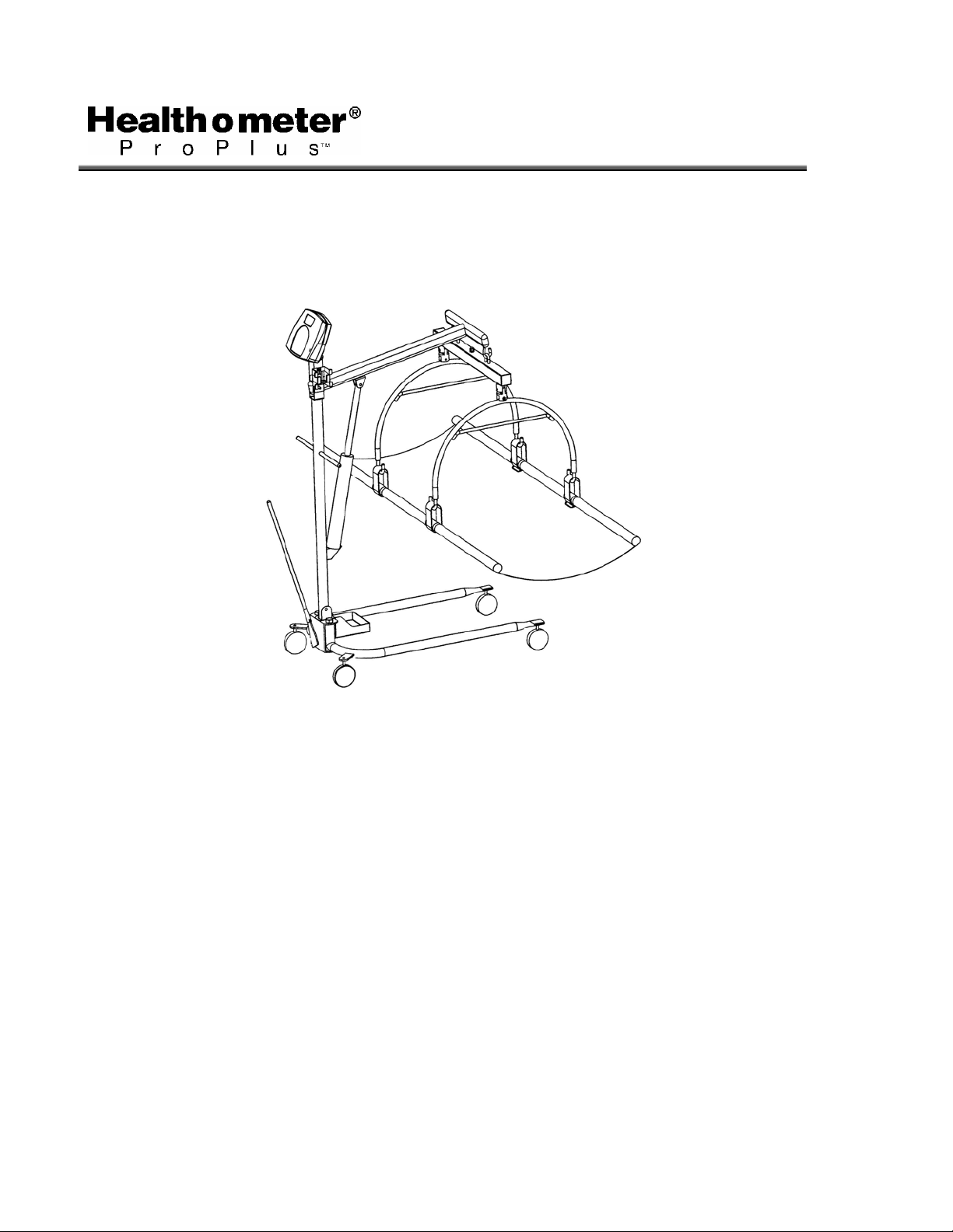
PRO PLUS® STRETCHER SCALE
MODEL 2000KL
OPERATION MANUAL
AA0339-0
Page 2

PRO PLUS® STRETCHER SCALE
MODEL 2000KL
Thank you
Please read this manual carefully and keep it handy for ready reference.
for your purchase of this product.
TABLE OF CONTENTS
CAUTION AND WARNING.................................................................................................... 2
SPECIFICATIONS.................................................................................................................3
ASSEMBLY INSTRUCTION.................................................................................................. 4
SET UP..................................................................................................................................10
OPERATION INSTRUCTIONS.............................................................................................. 11
MAINTENANCE.....................................................................................................................23
TROUBLESHOOTING........................................................................................................... 24
CALIBRATION PATH ............................................................................................................ 25
EXPLODED VIEW OF SCALE .............................................................................................. 25
PARTS LIST .......................................................................................................................... 27
WARRANTY .......................................................................................................................... 28
1
Page 3

CAUTION AND WARNING
To prevent injury and damage to your scale, please follow these instructions very carefully.
• To ensure proper operation of the ProPlus® Stretcher Scale, this operation manual should be
reviewed carefully before operation. Keep this manual available for future reference, and also
for use in the orientation of new personnel.
• If the scale becomes damaged, it should not be operated until properly serviced. All repairs
should only be performed by authorized Healthometer® Professional service personnel.
• This scale is designed for static weighing of patients only. No scale should be used for
patient transfer. Healthometer® Professional / Pelstar LLC assumes no responsibility
for patient injury or scale damage should this caution be ignored.
• Do not leave patients unattended while on the scale.
• For accurate weighing the scale must be placed on a flat and stable surface with the locking
screw locked properly and the weighing mechanism not touching the floor.
• For accurate weighing, verify proper operation according to the procedure described in this
manual before each use.
• Do not use in the presence of flammable materials.
• Operating at other voltages and frequencies than specified could damage the equipment.
• If the “LOW BAT” indicator activates, for accurate weighing, replace the batteries or connect
the scale to an AC power source as soon as possible.
• Failure to comply with the following will void scale warranty:
o Do not gas sterilize or autoclave the scale.
o Do not place liquids on top of the scale display console.
o Do not exceed recommended weigh limit of 400 lb/181kg for this
scale.
o This scale contains delicate sensors. Do not bang into doors,
elevators, etc., as damage may result.
2
Page 4

SPECIFICATIONS
GENERAL
Health o meter’s ProPlus® Stretcher Scale Model 2000KL uses highly sophisticated
microprocessor technology. This scale is designed to provide accurate, reliable and repeatable
weight measurements and features that make the weighing process simple, fast and convenient.
The scale is set up to use motion-sensing weighing technology, to determine the actual weight
of a moving patient. The scale may be changed to measure live weight; see page 19 for
instructions on changing the scale setting.
The weight can be displayed in pounds (decimals, fractions of a lb or lb/oz) or in kilograms. The
scale features a folding stretcher for easy mobility and a display assembly stand.
The unit can be operated using its AC adapter or by 6-D cell batteries (not included).
SCALE SPECIFICATIONS
Capacity and Resolution
Power Requirements
Environmental
Stretcher Dimensions Closed:
400 Lb x 0.2 Lb / ¼ lb / 4 oz (181 Kg x 0.1 Kg)
Adapter 120VAC - 6VDC - 60Hz or 6 x D size batteries
Operating temperatures: 50°F to 95°F (10°C to 35°C)
Storage temperatures: 30°F to 125°F (0°C to 50°C)
Humidity: 85%
Length: 70 ⅞” (180 cm)
Width: 6” (15 cm)
Weight: 16.5 Lb (7.5 Kg)
Fully extended:
Length: 70 ⅞” (180 cm)
Width: 29½” (75 cm)
3
Page 5
ASSEMBLY INSTRUCTIONS
Before Assembly
The Model 2000KL ProPlus® Stretcher Scale is shipped disassembled in two (2) separate
cartons. Carefully inspect all cartons for shipping damage before unpacking. If damage is found,
contact your shipper or Healthometer Professional immediately. Claims must be filed with the
shipper as soon as possible after receipt of the damaged package.
Remove each assembly from the carton and unwrap packing material carefully to prevent
scratching the unit’s parts. It is recommended that two people perform the assembly.
The scale is shipped in two (2) separate cartons as follows:
A. Large carton containing:
(1) Hydraulic pump assembly
(1) Lifter mast
(1) Base adjustment lever
(1) Lifter base with casters
B. Small carton containing:
(1) Lifter boom (1) Stretcher storage tray (4) Stretcher bars
(1) Display support (1) Adapter holder (2) Stretcher bar joint
(1) Display assembly (1) AC adapter (1) Hexagon screw with
(1) Load cell assembly (1) Display rear cover (2) Plastic washer
(2) Stretcher hoops (6) Screws for display
(1) Stretcher sheet (2) Shoulder screw and washer
Tools required: Phillips head screwdriver, adjustable wrenches, 7/16” Allen wrench.
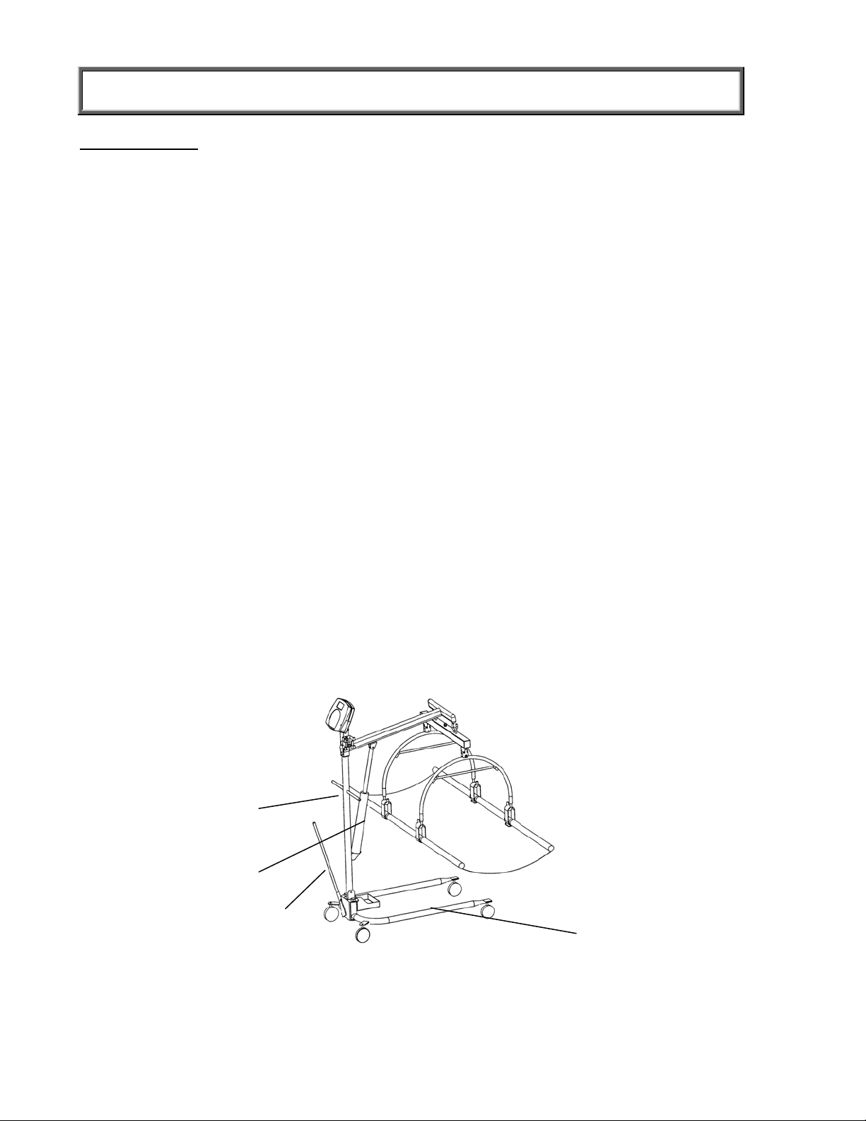
Parts of Stretcher Scale
Lifter mast
Hydraulic pump assembly
Base adjustment lever
L
Lifter base with casters
lock nut
(1) Velcro strap
Figure 1
4
Page 6
ASSEMBLY INSTRUCTIONS
Assembling the Patient Lifter
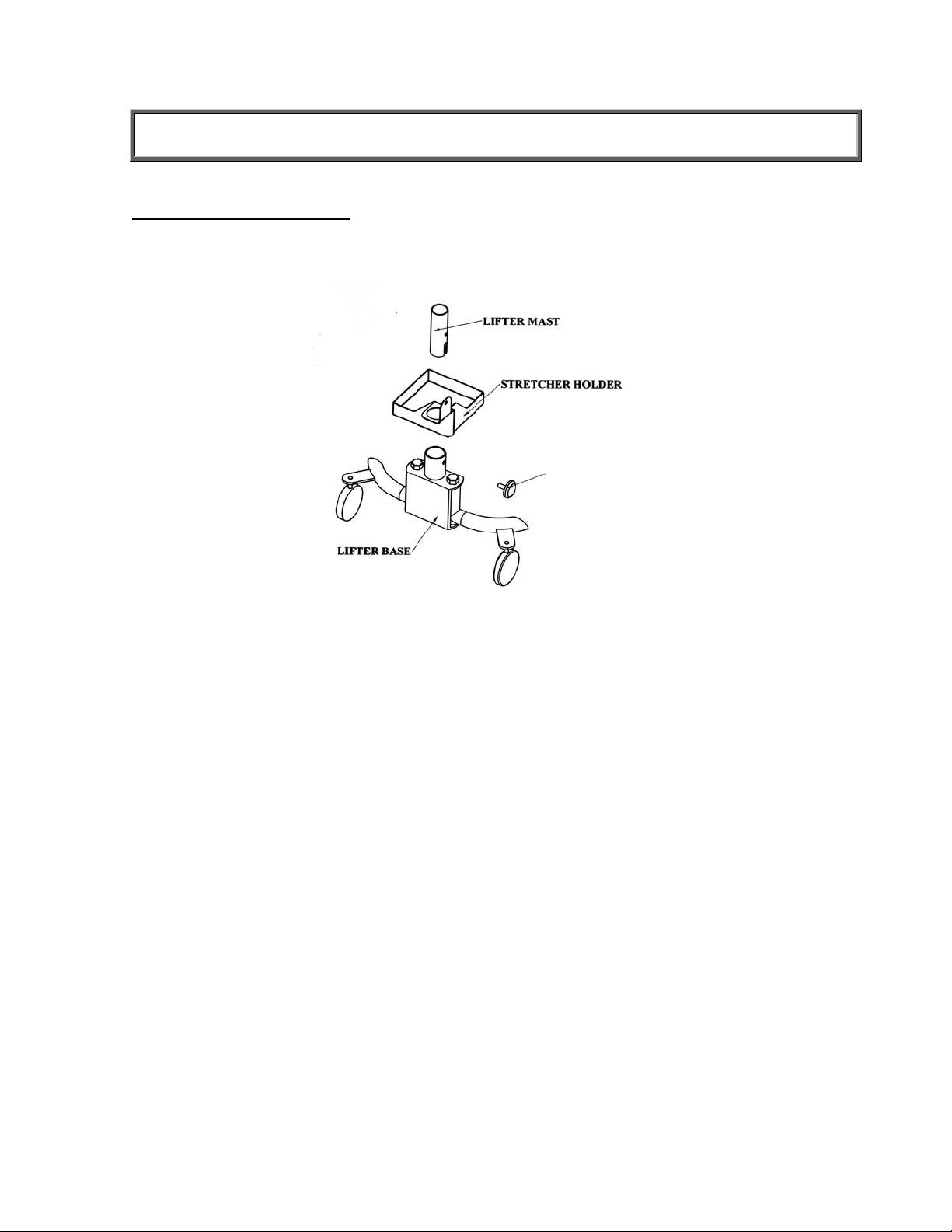
1. Place the Stretcher Storage Tray on the Lifter Base, as shown below, before attaching the
Lifter Mast.
KNOB
Figure 2
2. Remove black plastic protective caps from Lifter Mast. Insert the bottom of the Lifter
Mast and Hydraulic Pump assembly into the mast sleeve (through the Stretcher Tray
Holder) on the Lifter Base. The notch on the end of the mast fits over the round tube at
the bottom of the Mast Sleeve. The mast must lock into position in the mast sleeve,
making it impossible to rotate. Check that the mast is locked into position and that the
hole in the mast is aligned with the threaded hole in the mast sleeve.
3. Insert the threaded locking device (the plastic knob and stud chained to the base) into
the threaded hole in the mast sleeve. Tighten to lock the mast to the base. Keep mast
and base locked at all times except when removing mast from base for storage.
5
Page 7
ASSEMBLY INSTRUCTIONS
Attaching the Display and Scale to the Patient Lifter
PHILLIPS PAN HEAD
SCREW NC8-32x5/16
Figure 2
Figure 3
6
Page 8

ASSEMBLY INSTRUCTIONS
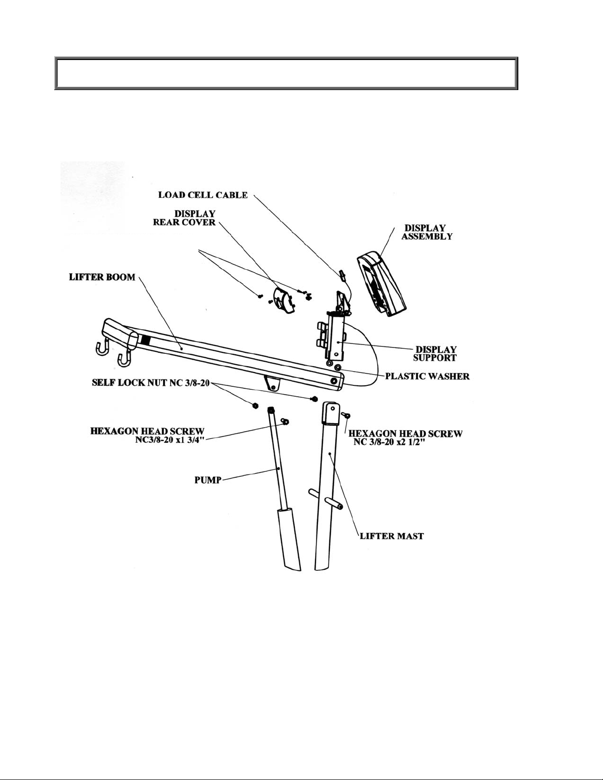
4. Connect the Lifter Boom and the Display Support to the Lifter Mast using the NC⅜-
20x2 ½” hex screw and tighten the self lock nut on its other side.
Note
: This screw is the axis of the Lifter Boom, so it is imperative that the three parts – Lifter
Boom, Lifter Mast and Display Support – be assembled in the proper order.
Place the Plastic Washers on either side of the Lifter Boom screw hole to prevent friction.
With the Boom hooks facing down, place the Lifter Boom and Washers inside the two
sides of the Lifter Mast and align the holes. Place the Display Support over the Lifter Mast
and Lifter Boom and align holes. Thread the screw through all three parts and tighten the
self lock nut on the other side well.
5. Insert the shaft end of the Pump into the eared bracket on the Lifter Boom and align the
holes. Slip the 1-3/4” nut through the bracket and the Pump shaft hole. Tighten with
locknut.
6. Insert the Base Adjustment Lever into its socket at the back of the Lifter Base. Check to
see that the bump on the outside of the socket fits securely in the notched adjusting
plate. To adjust the base legs, pull back on the adjusting lever to unlock. Move the lever
to the right to widen the base.
7. A wheel lock is provided on the Lifter Base for parking only. To lock caster, step on cam
lever on side of caster. To unlock, step on higher cam lever. NOTE: Never lock wheel
lock or block wheels when lifting someone. Wheel lock is provided for parking the Lifter
only,
8. Check the operation of the Hydraulic Pump by pumping the handle to elevate the Boom.
Make certain the control valve knob – located on the pump near the handle) is fully
tightened (clockwise).
9. To lower the Boom, slowly turn the control valve knob counterclockwise. The rate of
descent can be controlled by how much the knob is turned. The Boom may not lower
readily with weight. To test, simply apply downward force to the Boom.
Note
: If bolts, mounting pump or Lifter Mast are too tight, the Boom may not lower properly.
7
Page 9
ASSEMBLY INSTRUCTIONS
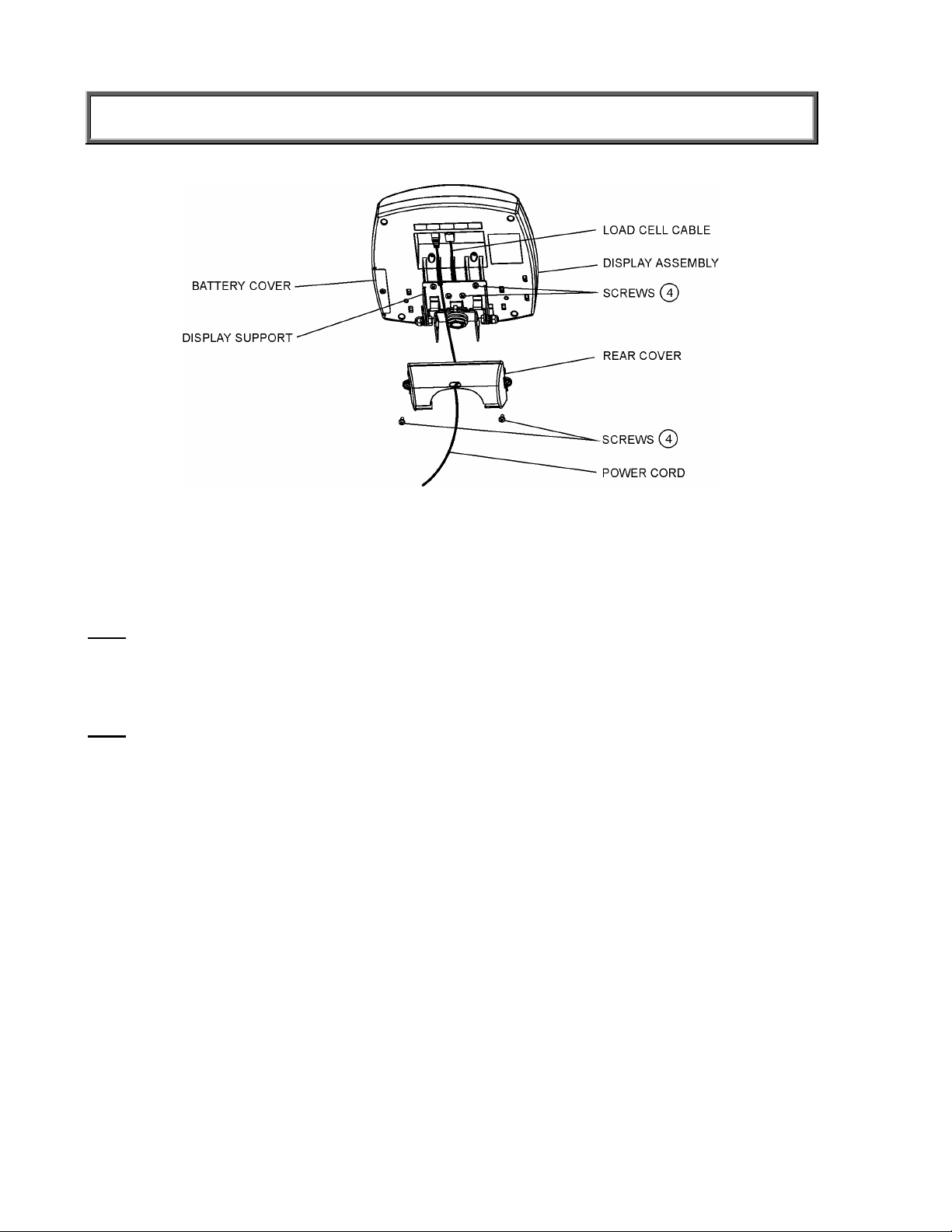
Figure 4
10. Position the Display Assembly close to the Display Support. Connect the load cell cable
connector to the load cell port on the rear of the Display Assembly and insert and secure the
cable into the center channel in the display.
Note
: Do not attach the power cord at this point.
11. Slide the display assembly onto the display support by inserting the two metal supports into
the two slots in the rear display assembly. Tuck the excess load cell cable in the Lifter Boom
tube.
Note
: The load cell cable should now be secured in the channel between the display assembly
and the display support.
12. Insert 4 screws into the display support and tighten.
13. Connect power cord to the power port in the display assembly and insert and secure the
cable into the exposed portion of the 2nd channel from the left in the display.
14. Insert the power cord into the retaining slot on the rear cover. Align the rear cover tabs with
the slots on the rear of the display assembly. Apply pressure to snap the rear cover into
place and secure with 2 screws.
8
Page 10

ASSEMBLY INSTRUCTIONS
Figure 5
15. Hang the Load Cell Assembly on the two hooks at the end of the Lifter Boom, using the
loops on top of the Load Cell Assembly.
16. Connect the end of the Load Cell Cable coming out of the center of the Load Cell Assembly
to its port in the Lifter Boom.
17 Use the two washers and shoulder screws to connect the two Stretcher Hoops to the Load
Cell Assembly and tighten well.
18. Connect the two right stretcher bars by screwing them onto one Stretcher Bar Connector, in
order to make one long Stretcher Bar.
19. Repeat step 9 with the left Stretcher Bar.
20. Insert the two bars into the open side of the channel-pockets in the Stretcher Sheet and
through the two hanging loops sewn into both sides of the Stretcher. The Stretcher Bars
should not protrude from the Stretcher Sheet at either end. Make sure one end on both
channel-pockets is sealed with Velcro.
Note
: Make sure the bars are inserted into the two hanging loops sewn on both sides of the
stretcher. This will ensure that the Stretcher Bars hang correctly from the hanging loops.
9
Page 11

SET UP
Preparing the Scale for Use
1. Remove protective plastic film from keypad and display.
2. Place batteries in the battery holder (see “Replacing Batteries”).
3. Plug the scale’s AC adapter into the power source.
4. Press the ON/OFF button to turn the scale on. The display will show “Health o Meter
Pro-Plus” and then ”000
Lb00oz”.
the display will show a negative weight equivalent to the weight of the Stretcher.
5. Hang the stretcher on the Stretcher Hoops to register a 0 weight on the display. Press the
Tare key if necessary.
6. Place a weight [not exceeding 400 Lb (180 Kg)] on the stretcher. The display should read
the correct weight.
7. Press the KG/LB button to select the weight mode (Lb/Kg).
8. Press the Reweigh button; the scale should perform the weighing process again. The
display should read “WEIGHING” until the weight calculation is complete and the weight is
displayed.
9. Remove the weight from the stretcher, the scale will return to zero and the display will read
“ZERO” on the left upper side of the screen along with
10. Disconnect the scale’s AC adapter from the power source, and the scale will switch to
battery power.
(a)
If the Stretcher weight has previously been tared out,
(b)
*
”000Lb00oz”.
Note
: If the set up procedure failed, refer to the troubleshooting instructions. If the problem is
not corrected, refer to qualified service personnel.
(a)
To adjust the display backlight and/or contrast, please refer to page 19.
(b)
To change the display mode in pounds to fractions or decimals, please refer to page 14.
Replacing Batteries
Figure 6. Replacing Batteries
#
(refer to the Parts List on page 25 for details on parts followed by
)
1. Unplug the scale.
2. Remove the battery cover from the display assembly.
3. Disconnect battery holder cable connector from the scale-battery connector.
4. Carefully remove the battery holder by sliding it out of the display assembly.
5. Replace the batteries with new ones.**
6. Carefully slide the battery holder into the display assembly.
7. Plug the battery holder cable connector to the scale-battery connector.
8. Attach the battery cover to the display assembly and install the screw.
* To change the scale default units to kilograms, or to deactivate the LB/KG button,
please contact Technical Support at 1 800 638-3722 or +1 708 598-9100.
** We recommend the use of EVEREADY Energizer
®
e2TM batteries.
10
Page 12

OPERATION INSTRUCTIONS
Preweighing the Stretcher
1. Make sure the scale is free of load (nothing is hanging from it), including the stretcher.
2. Press the ON/OFF button to turn the scale on.
3. Wait until ”000
scale will remember the last amount that was tared, so if the weight of the stretcher
had previously been tared, the scale will display a negative weight when it is turned
on again.
Note
: The ‘ZERO’ sign will show on the upper left side of the display only when the scale is free
of load, including the stretcher.
4. If the weight of the stretcher is known, enter the TARE value according to instructions in
the “Menu”, para 02. If the stretcher’s weight is unknown, place the stretcher only on the
scale; press REWEIGH. Enter the Automatic TARE by pressing the TARE button. Display
will read ”000
Note
: Once the tare is set the “TARE” sign will appear in the upper right side of the display.
Placing Patient in Stretcher
1. After setting the stretcher’s weight as tare, take the stretcher off the lifter. The display will
now show a negative weight, equivalent to the weight of the stretcher.
2. Lay the stretcher on a bed or on any other stable surface you can use to lay the patient
you wish to weigh.
3. Carefully move the patient to a lying position on the stretcher.
Note: lay the patient’s center mass as close as you can to the center of the stretcher.
4. Wheel the lifter scale close to the stretcher and lower the boom with the hoops as far as 5-
10” (12 cm -25 cm) from the patient’s body.
5. Connect the four hanging loops of the stretcher to the four hooks at the end of each
Stretcher Hoop, making sure that the loops are hanging freely from the four hooks.
Note: Make sure both hooks connecting the load cell assembly beam lie on the lifter boom. If
only one of the hooks lies on the beam it can cause inaccurate readings of weight.
6. Tighten the hydraulic control valve knob by turning it clockwise. The control valve knob is
located on the Pump near the Pump handle.
7. Use the Base Adjustment Lever to widen the Lifter Base. The Base must be spread to the
widest possible position to maximize stability.
8. Pump the hydraulic Pump handle to lift the Stretcher and patient until the entire Stretcher
is hanging from the Stretcher Hoops and is not touching the bed or any other object. Do
not lock the Wheel on the Lifter Base. If needed, the Base will move slightly to adjust for
balance.
Caution: Never move patient away from bed or leave patient unattended.
Taking Weight Measurements
1. The scale will calculate the patient’s weight. Depending upon the movement of the
stretcher, the scale may take several seconds to lock into the weight. We recommend
reweighing after the patient is lying still on the stretcher by pressing the REWEIGH button.
2. After weight measurement is obtained and recorded, lower the Stretcher and the patient to
the bed. Open the hydraulic pump control valve knob by turning it counterclockwise very
slowly to control the descent.
3. Guide the patient and Stretcher down onto the bed.
Lb00oz” and “ZERO” on the left side of the display will appear. The
Lb00oz”.
11
Page 13

OPERATION INSTRUCTIONS
4. Release the hanging loops from the lifter.
Note
: The scale is programmed to save the last setting chosen as well as the weight of the
stretcher as tare weight. This enables weighing a number of patients without having to reset the scale.
If a weight was added or reduced from the stretcher scale it is required to reset the tare
weight.
Note
: To zero the scale by using the ZERO key, take the stretcher off the lifter before pressing
ZERO key. Replace the stretcher after zeroing.
5. Press ON/OFF key to turn scale off.
12
Page 14

OPERATION INSTRUCTIONS
Figure 7. Keypad
ITEM DESCRIPTION FUNCTION
POWER Turns scale ON and OFF.
ZERO Zeros the scale prior to weighing.
Holds the value of the weighed object on the display until
HOLD/RELEASE
REWEIGH
KG/LB button
MENU Enters the menu of the scale.
BMI
PRINT Prints patient’s data (if printer is connected to the scale).
ID
TARE
EXIT
the button is pressed again to clear the value. Also used to
scroll down in the menu.
Allows repeated weighing of the patient without stepping
off the scale.
Toggles between kilograms or pounds. Also used to scroll
up in the menu.
Prompts entry of data to calculate the patient’s Body Mass
Index (BMI).
Prompts entry of patient’s identification number (ID). This
ID will be stored with all the weighing made until is cleared
or a different ID is stored.
Prompts entry of TARE value that will be deducted from
the weight on the platform. Also releases tare weight
(returns display to zero).
Reverts back one step when in the menu and data entry
modes.
ENTER Used to enter commands and values into the scale.
13
Page 15

OPERATION INSTRUCTIONS
MENU
In the menu screen the user can set preferences and/or instruct the scale how to handle stored
data. The menu can be navigated using the up and down keys (cd) or by entering the
associated menu position number with the keypad. The menu has a “roll-over” way of working:
when the user scrolls to the bottom of the menu and presses the down button, it will return to the
top of the menu.
Figure 8. Main Menu
01 WEIGHT DISPLAY MODE
(only applies to pound values, NOT the metric values)
The user can set the screen display value in either fraction of pound (¼, ½ or ¾ lb), in pounds
and ounces (resolution of 4 ounces) or in decimals (resolution of 0.2 lb). When kg is selected as
the units of use, these settings have no effect. The mode that is selected is used through all the
screens.
Figure 9. Weight Display Mode
14
Page 16

OPERATION INSTRUCTIONS
02 TARE WEIGHT
NOTE: Due to the scale’s sensitivity, we recommend using the REWEIGH function prior to
setting the TARE weight, in order to eliminate any operator interference with the item to
be tared out.
There are two ways to manually enter a tare weight (such as the weight of a stretcher , shoes,
etc): press MENU (1) and select option 02-Tare Weight or press TARE (9). If there is no weight
on the scale platform (value displayed is zero and there is no tare) and the user presses the
TARE button (9), the Tare Weight window appears and prompts the user to enter the TARE
value and to press ENTER. NOTE: The tare weight must be entered using the following
increments: 4oz, 0.2lb, ¼lb. The value entered will display in minus (-). After the TARE has been
entered, the scale goes back to normal operation. This TARE value is stored in memory until
changed or cleared.
Important: The TARE weight cannot exceed 125 lb.
The number that is to be changed will
flash and will move from the left to the
right after the appropriate number was
entered or by using the c key (left)
and the d key (right).
TARE display
indicates the weight
that has been tared
out
Figure 10. Tare Weight
Automatic Tare
The user can set a tare weight by pressing the TARE button (9) while there is a weight on the
scale platform. The display will come to zero and TARE will be displayed to indicate there is a
tare value in the memory (as displayed in Figure 10 above).
Removing the Tare
Additional pressing of the TARE button will delete the tare value from memory, TARE will
disappear from the display and the scale will resume normal operation.
03 DATA MANAGEMENT
The scale manages patient data including patient ID, weight, height, tare and BMI. The value is
stored in memory or transferred to PC. This function is performed by opening a new data file.
OPENING A NEW DATA FILE:
1. Press the ID button (7).
2. Using the keypad, type in the identification number.
3. Press ENTER.
This scale will also calculate Body Mass Index (BMI).
CALCULATING BMI:
1. Place the patient on the scale platform.
2. Press the BMI button (2).
15
Page 17

OPERATION INSTRUCTIONS
3. The scale will prompt you to enter the patient’s height. Use the keypad to enter the height in
1/4" (1=1/4, 2=1/2, 3=3/4) or 1 cm increments (use inches for weight in lb, cm for kg). Press
ENTER.
4. Display will read the patient’s BMI.
The scale offers you two options to manage your information: to transfer/download the values or
to store them. The first option automatically downloads (transfers) the value to your PC. The
second option stores the value in memory. The maximum capacity of the scale is 270 files of
different data.
01 Auto Download
02 Store in memory
03 Do not store data
Automatic Download is the default option and will transfer the
value to the PC as soon as the patient steps off the scale or
when the user presses the HOLD/RELEASE button if it was
kept in “HOLD”. If no PC is connected, the value is not
transferred and not stored and will be lost after the load is
removed from the scale.
The value is stored in memory
for later download to PC.
If the memory is close to full
the user will be warned and
given the option to transfer all
values to the PC or to clear
the memory of all values.
All the data will be cleared.
16
Page 18

OPERATION INSTRUCTIONS
04 Transfer now
05 Clear memory
04 SCALE SETTINGS
All the values stored in memory are transferred to the PC and
the scale memory is cleared of all values. If the transfer was
unsuccessful, the values are kept in memory until
successfully transferred or cleared.
All the values stored in memory will be cleared.
01 Auto Hold Time
02 Sleep Time
The user can determine how long to display the weight
reading once it is determined, regardless of whether the
patient remains on the platform. The scale defaults to no Auto
Hold Time. The maximum setting is 20 seconds Hold Time.
The user can set the time elapsed before the scale goes into
the sleep mode. The default is 1 minute. When the scale
goes into sleep mode, STANDBY is displayed on the screen.
17
Page 19

OPERATION INSTRUCTIONS
03 Auto Off Time
04 Tone Volume
The user can determine how long the scale will operate
before turning off automatically due to inactivity. Default
time is 10 minutes. If the value is set to zero, the auto off
function is disabled.
There is an option to adjust the beeping tone of the scale.
This tone should sound when the scale has determined
the weight on the platform, when a key is pressed, after
the scale is turned on, at the end of self-test, or in the case
of fault or warning.
Use the c and d keys on the keypad to adjust the
volume.
Whenever the user presses the key to change a volume, a
beep will sound to indicate the set volume level.
05 Display Date and Time
This option will turn on or
turn off the date and time
display.
18
Page 20

OPERATION INSTRUCTIONS
06 Display Backlight
07 Display Contrast
08 Live Weight
The user can set the brightness of the backlight.
The user can set the brightness of the LCD.
By selecting “Yes” the user can set the Live Weight mode
to deactivate the motion-sensing mode. In the Live Weight
mode the weight displayed will fluctuate with the patient’s
movement; the scale will not lock on quickly to the weight
as is the case in the motion-sensing mode.
Press the REWEIGH button to operate the motion-sensing
mode and to determine the correct weight on the screen.
To revert back to motion-sensing mode, change the Live
Weight setting to “No”.
05 SYSTEM SETTINGS
01 Set Time & Date
The user can set the time and date using the keypad.
To set the time move between hours, minutes and
seconds using the up and down keys cd and enter the
values on the keypad. To jump to the AM/PM line press
the ENTER button once.
19
Page 21

OPERATION INSTRUCTIONS
Set the date using the up and down keys cd and enter the
values on the keypad.
02 About
06 SYSTEM TEST
This screen displays the software version of the scale.
01 Battery Test
02 USB Connection
The scale will display the estimated amount of battery life
remaining until the batteries will have to be replaced.
NOTE: In order to complete the battery test, the scale must be
powered by batteries only. Unplug the scale from AC power
source prior to battery test.
The scale will test the connection to the PC and will display a
message “Connection is OK” or ”NO Connection”.
If “NO Connection” is displayed, check your USB connections
on the scale and on your PC and retest the connection. Refer
to qualified service personnel if problem persists.
20
Page 22

OPERATION INSTRUCTIONS
03 UI Test
The scale has a diagnostic routine where it tests the User
Interface (UI) hardware functionality (LCD, keypad). In order to
do this the user has to press all the keys according to the
messages displayed on the screen.
07 USER SETTINGS
If the requested command was not received or wrong button
was pressed, the following message will be displayed.
If after 10 seconds the requested command was not received,
the following message will be displayed. If “UI Error Failure” is
displayed, refer to qualified service personnel.
01 Retain Entered Values
This option allows the user to use the same values for ID,
height and TARE between weighing. If this option is disabled,
the user has to re-enter these values for each reading. If the
values are not entered, only the weight is stored.
NOTE: These values cannot be retained by ID number.
21
Page 23

OPERATION INSTRUCTIONS
02 Disp Height & ID
When the user selects to
display the height and ID of the
user, it will be displayed at the
bottom of the screen. We
recommend the use of this
function to ensure that the
patient’s correct ID and height
have been entered.
03 Prompt For Height
04 Prompt For ID
When this option is activated,
the user will be asked to enter
the patient’s height after every
weighing.
When this option is activated,
the user will be asked to enter
the patient’s ID number after
every weighing.
22
Page 24

MAINTENANCE
GENERAL
This section provides instructions for maintenance, cleaning, troubleshooting and operator
replaceable parts for the ProPlus
than those described in this section should be performed by qualified service personnel.
®
Stretcher Scale Model 2000KL. Maintenance operations other
MAINTENANCE
Before first use and after periods of non-use, check the scale for proper operation and function.
If the scale does not operate correctly, refer to qualified service personnel.
1. Check overall appearance of the total scale for any obvious damage, wear and tear.
2. Inspect AC adapter for cord cracking or fraying or for broken or bent prongs.
CLEANING
Proper care and cleaning is essential to ensure a long life of accurate and effective operation.
Disconnect the scale from the AC power source.
1. Clean all external surfaces with a clean damp cloth or tissue. Mild soap and water solution
may be used. Dry with a clean soft cloth.
2. Do not immerse the scale into cleaning or other liquid solution.
3. Do not use Isopropyl Alcohol or other solutions to clean the display surface.
23
Page 25

TROUBLESHOOTING
Refer to the following instructions to check and correct any failure before contacting service
personnel.
SYMPTOM POSSIBLE CAUSE CORRECTIVE ACTION
Scale does not turn on 1. Dead Battery
2. Faulty electrical outlet
3. Bad power supply
Questionable weight or
the scale does not zero
1. External object
interfering with the scale
2. The weight of the
stretcher as tare was not
set correctly
1. Replace batteries
2. Use a different outlet
3. Replace adapter
1. Remove interfering object
from the scale
2. Take the patient and the
stretcher off the scale,
zero the scale, hang the
stretcher on the scale and
enter the tare weight.
After the tare weight is set
start weighing action.
3. The patient’s center
mass is not at the center
of the stretcher and one
of the hanging hooks of
the lifter boom does not
3. Take the patient off the
stretcher and re-position
so that the center mass
will lie between the two
hoops.
lie on the lifter beam.
4. Scale is out of calibration 4. Check weight with known
weight value
Weighing is performed but
the display shows “weigh”
and “reweigh” every few
The patient is not still Ask the patient to be still or
change the scale to use the
live weight setting (p.19).
seconds; the weighing
process takes too long and
no weight is displayed.
The display shows
“Overload” message
The display shows
“LOW BAT” message
The display shows
“Load Cell Error” message
The load on the scale
exceeds the capacity
(400 Lbs)
Remove the excess weight
and use the scale according to
its limits
The batteries are empty Replace batteries according to
instructions
There is a problem with one
or more load cells or the load
cell cable is disconnected.
Check load cell cable
connection at the display and
platform assembly ports. If the
problem is not corrected, refer
to qualified service personnel
to replace the defective load
cell
24
Page 26

CALIBRATION PATH
The calibration is performed in Kg or Lb, according to the units of measure used upon entering
into the calibration path.
Operator Action Display
1. Press ON/OFF button and immediately press
and hold HOLD/RELEASE button for 3-4
seconds
2. Press ENTER Enter load weight
3. Using cd keys and/or the keypad, set the
calibration load to at least 200 lbs (for best
results and greater accuracy, use a 400 lb
weight). Press ENTER
4. Please clear the stretcher and press ENTER Zero calibration
5. Please wait without touching or shaking the
scale until the zero calibration process is
finished
6. Load the stretcher with the required weight and
press ENTER
7. Please wait without touching or shaking the
scale until the calibration process is finished
8. Press ENTER Calibration
9. Please remove weight from the stretcher Rebooting
10. Please wait until the scale resumes normal
operation
Calibration
Process
400.0
Zero calibration
Please clear the scale
Please wait
Weight calibration
Put: XXX.X
Weight calibration
Please wait
Calibration
factor: X.XXXXX
Please clear the scale
Please wait
Health O Meter
Pro Plus
37
EXPLODED VIEW OF SCALE
38
39
40 41
42
43 44
52
25
45 46
51
47
48
50
49
Page 27

EXPLODED VIEW OF SCALE (continue)
26
Page 28

PARTS LIST
Key No. Part No. Description Qty.
1 1109403-0 DISPLAY ASSEMBLY 1
2 2268101-0 TILT MECH. ASSEMBLY 1
3 3848401-0 PLASTIC WASHER 2
4 401369 PLASTIC OVAL BAR COVER 3
5 HEX. HEAD SCREW NC 3/8-16*2 1/2 1
6 HEX. HEAD SCREW NC 3/8-16*1 3/4 1
7 2268001-0 LIFTER BOOM ASSEMBLY 1
8 2034701-0 MAIN BOARD TO CON. DIG CABLE 1
9 3809801-0 BEAM ASSEMBLY 1
10 PHIL.PAN HEAD SCREW NC6-32*1/4” 2
11 2138903-0 CON. DIG BOARD 1
12 SPACER WITH EX.THREAD STUD NC6*1/4” 2
13 SOCKET BUTTON HEAD CAP SCREW NC1/4-20*3/4” 2
14 SAFETY WASHER NC3/8” 2
15 401304 HEX. SOCKET HEAD SCREW NC3/8-16*1 1/2 2
16 3808401-0 STRETCHER HOOP 2
17 401338 STRETCHER 1
18 3835701-0 STRETCHER STORAGE TRAY 1
19 3833801-0 BAR ADAPTER 2
20 3808501-0 STRETCHER BAR 4
21 3816901-0 FORK JOINT 2
22 HEX. SOCKET HEAD SHOULDER SCREW (5/16) 3/8-1” 4
23 3816801-0 LOAD CELL ADAPTER 2
24 3828301-0 LOAD CELL CONNECTING BEAM 1
25 1304202-0 LOAD CELL 2
26 HEX. SOCKET HEAD CAP SCREW NC5/16-18*3/4” 4
27 NUT NC3/8” 2
28 401337 PLASTIC RHS50*50 COVER 2
29 400579 CABLE HOLDER P.G.-7 1
30 400066 SELF LOCK NUT NC3/8” 2
31 PHIL. PAN HEAD SCREW NC8*3/8” 6
32 3822701-0 CABLE COVER 1
33 400412 SELF LOCK NUT NC6 2
34 PHIL. PAN HEAD SCREW NC6-32*3/8” 2
35 3817001-0 ADATPER HOLDER 1
36 420988 ADAPTER 6VDC 120VAC 1
37 411220 KEYPAD 400LB 1
38 INDICATOR COVER 1
39 LCD WINDOW 1
40 LCD BOARD 1
41 WN1412 CROSS HEAD SCREW K22L6 4
42 DISPLAY TO EAGLE P.C.B CABLE 1
43 WN1412 CROSS HEAD SCREW K30L6 4
44 EAGLE BOARD 1
45 INDICATOR BASE 1
46 PHIL. PAN HEAD SCREW NC6-32*3/8” 6
47 MODEL LABEL 1
48 3245801-0 INPUT/OUTPUT PORTS LABEL 1
49 PHIL. PAN HEAD SCREW NC4-40*1/4” 1
50 3822801-0 BATTERY COVER 1
51 400152 RUBBER O RING 1
52 2033801-0 BATTERY HOLDER 1
--- 63855 PATIENT LIFT 1
27
Page 29

WARRANTY
LIMITED WARRANTY
What does the Warranty Cover?
Pelstar LLC scales are warranted from date of purchase against defects of materials or in
workmanship for a period of three (3) years. If product fails to function properly, return the
product, freight prepaid and properly packed to Pelstar. See “To Get Warranty Service” below for
instructions. If manufacturer determines that a defect of material or in workmanship exists,
customers' sole remedy will be repair or replacement of scale at no charge. Replacement will be
made with a new or remanufactured product or component. If the product is no longer available,
replacement may be made with a similar product of equal or greater value. All parts including
repaired and replaced parts are covered only for the original warranty period.
Who is Covered?
The original purchaser of the product must have proof of purchase to receive warranty service.
Pelstar dealers or retail stores selling Pelstar products do not have the right to alter, or modify or
any way change the terms and conditions of this warranty.
What is Excluded?
Your warranty does not cover normal wear of parts or damage resulting from any of the
following: negligent use or misuse of the product, use on improper voltage or current, use
contrary to the operating instruction, abuse including tampering, damage in transit, or
unauthorized repair or alternations. Further, the warranty does not cover Acts of God, such as
fire, flood, hurricanes and tornadoes. This warranty gives you specific legal rights, and you may
also have other rights that vary from country to country, state to state, province to province or
jurisdiction to jurisdiction.
To get Warranty Service
Make sure you keep your sales receipt or document showing proof of purchase.
Call 1 (800) 638-3722 or 1 (708) 598-9100 to receive a return authorization number. Attach
proof of purchase to your defective product along with your name, address, daytime telephone
number and description of the problem. Carefully package the product and send with shipping
and insurance prepaid to:
Pelstar LLC
Attention R/A#_____________
Repair Department
7400 W. 100th Place
Bridgeview, IL 60455
If your scale is not covered by warranty, or has been damaged, an estimate of repair costs or
replacement costs will be provided to you for approval prior to servicing or replacing.
Pelstar LLC
7400 West 100th Place, Bridgeview IL 60455 • 1-800-638-3722 or 1-708-598-9100
www.healthometermedical.com
Health o meter ProPlus® products are manufactured, designed and owned by Pelstar LLC.
Health o meter® is a registered trademark of Sunbeam Products Inc., Boca Raton, FL 33431.
ProPlus® is a trademark of Pelstar LLC
Patents Pending
28
 Loading...