


SHELBOURNE
Grain Header Manual
09032101g
HEADSIGHT.COM | 574.546.5022


About Headsight
Headsight Contact Info
Headsight, Inc.
4845 3B Road
Bremen, IN 46506
Phone: 574-546-5022
Fax: 574-546-5760
Email: info@headsight.com
Web: www.headsight.com
Technical Assistance
Phone: 574-220-5511
About this Manual
How to use this manual
The instructions in this manual are in the order that they should be completed for new installations.
Complete all applicable instructions in each section before proceeding. Note that some sections are
labeled to indicate they only apply to certain machines or applications. An index is available in the front
of the manual to help nd technical information for previously installed systems.
This icon designates information of which
you should take note.
This icon designates an important
instruction.
This icon indicates a special tool needed
for a given task.
Disclaimers
Headsight®, Horizon®, Pinpoint®, Insight®, Foresight®, Feathersight® Truesense™ and Truesight® are
trademarks of Headsight, Inc. All other trademarks are property of their respective owners.
Suggestions
If you have any suggestions to improve this manual please call 574-546-5022 or email info@headsight.
com.
Headsight’s products are protected by one or more of the following US Patents 6202395,
6833299, 7310931, 7647753, 9609806 and other patents pending.
Copyright Headsight, Inc. 2018
i

Table of Contents
About Headsight ��������������������������������������������������������������������������������������������� i
About this Manual ������������������������������������������������������������������������������������������� i
Installation �������������������������������������������������������������������������������������������������� 1
Install Terrace Sensors (if equipped) ����������������������������������������������������������������� 2
Terrace Sensor Overview ������������������������������������������������������������������������������ 2
Mounting Sensors to Terrace Tube Brackets ������������������������������������������������������� 3
All models except XCS/XCV �������������������������������������������������������������������������� 4
All XCS/XCV models ������������������������������������������������������������������������������������ 6
Install Standard Mount Sensor (if equipped) �������������������������������������������������������� 8
Mounting Sensors to Undermount Brackets ������������������������������������������������������� 8
All models except XCS/XCV ���������������������������������������������������������������������������� 9
All XCS/XCV models �����������������������������������������������������������������������������������10
Route Wiring ���������������������������������������������������������������������������������������������12
Harness Length Table ���������������������������������������������������������������������������������12
Weatherpack Removal ��������������������������������������������������������������������������������12
Install 6ft Terrace Sensor Harnesses in Terrace Tubes (if equipped) �������������������������13
Route Left Terrace Sensor Harness to Feederhouse ���������������������������������������������15
Install Under Mount Wiring (if equipped) ���������������������������������������������������������16
Install Controller ��������������������������������������������������������������������������������������18
Sensor Adjustment ����������������������������������������������������������������������������������������19
Terrace Sensor �������������������������������������������������������������������������������������������19
Increasing or Decreasing Voltage �������������������������������������������������������������������19
Adjusting Voltage Swing ������������������������������������������������������������������������������19
Adjusting Down Pressure ����������������������������������������������������������������������������19
Parts ���������������������������������������������������������������������������������������������������������20
STATEMENT OF LIMITED WARRANTY �����������������������������������������������������������������21
ii

Installation
Before working under header always:
1. Perform all combine and header manufacturer safety
precautions for servicing header.
2. Insert stop to prevent movement of header.
3. Turn off combine and remove key from ignition.
4. Set combine parking brake.
5. Disconnect all drive shafts from the header.
Installation
1

Installation
Complete the installation portion of this header manual before continuing.
Install Terrace Sensors (if equipped)
Terrace Sensor Overview
1. Correct header setup is essential for proper operation
and protection of Terrace sensors.
• As recommended in Shelbourne’s operator’s manual,
the bottom plane of the end panel must be level or
tipped slightly upward when the header is near the
ground (at the lowest intended operation position).
2. Terrace sensor tube brackets supplied by Headsight
after 2017 have a height adjustment.
• For most crop conditions, assemble the terrace tube
bracket straight as shown - for maximum cut height
• For very short crop (or when trying to pick up down
crop) it may be necessary to position the terrace tube
bracket in its raised setting - to protect the sensor by
providing adequate clearance between the sensor
and the ground.
2

3. Pre-assemble the tubes for the desired height setting
(straight or raised) before proceeding with the installation.
• Use hardware provided in kit B660
Any time terrace tube position is adjusted, be cautious not to crush the wire routed in the tube.
The Headsight controller and combine will need to be recalibrated. Calibrate header controller
then combine any time terrace tube is adjusted.
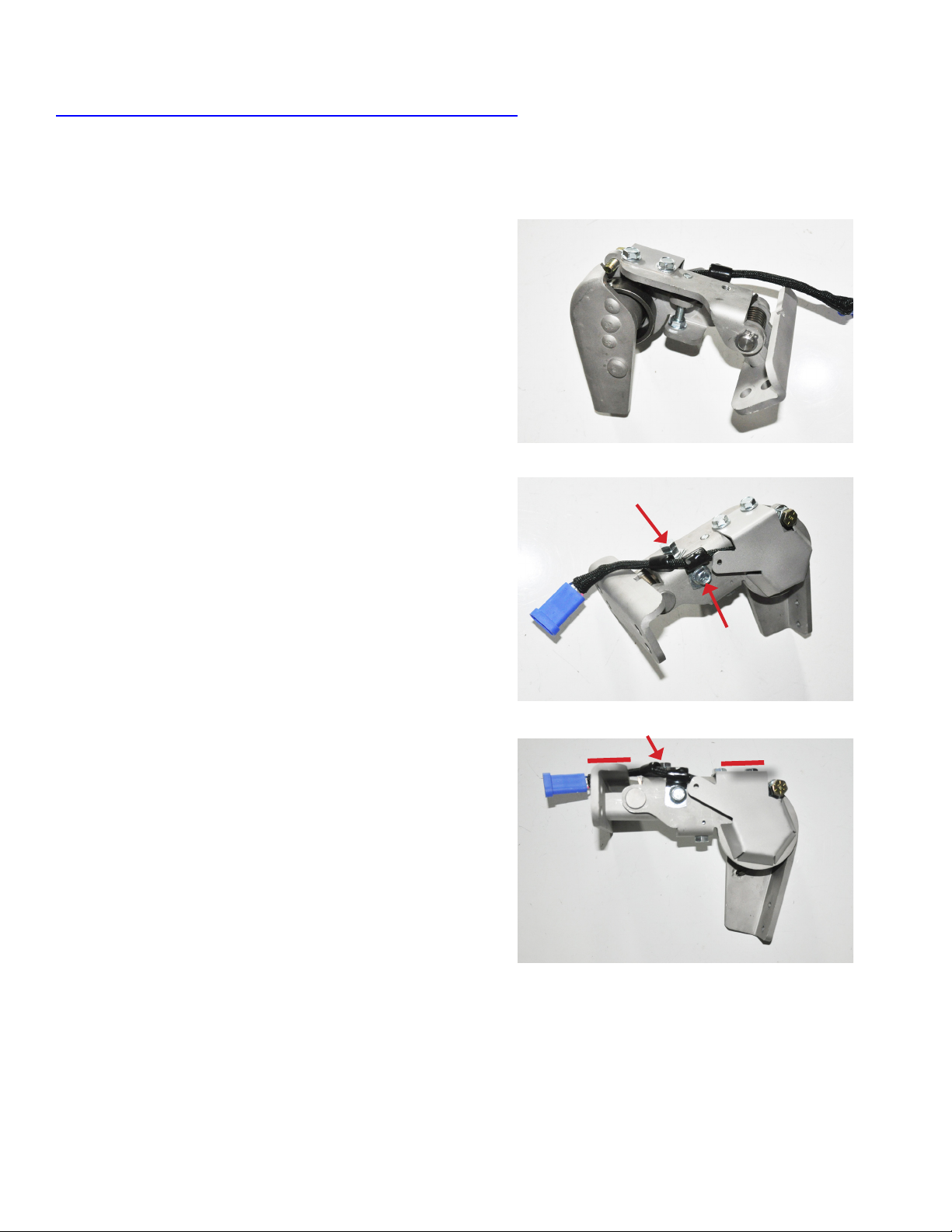
Mounting Sensors to Terrace Tube Brackets
1. Align holes in sensor and mounting bracket with spring.
• Spring must be installed short leg up and long leg
back in mounting tube
• Use hardware provided in kit B7000
Installation
2. Insert pin and secure with retaining ring.
3. Install clamp, leveling bolt (A), and jam nut.
• Place wire clamp over wire tail
• Install jam nut onto bolt
• Insert bolt through wire clamp and thread into sensor
• This bolt will be adjusted to level sensor after the tube
has been mounted on the head
4. Tighten bolt (B) holding clamp on side of sensor.
A
B
3

Installation
All models except XCS/XCV
1. Install parking stands.
2. Remove existing two bolts and discard bolts.
3. Install mounting tube to left end of head with hardware
provided in kit BWT2S.
• Enlarge front bolt hole if necessary
• A washer may be needed between bracket and frame
on front bolt for alignment
• Stand in front of header and make sure tube is
parallel with end panel
4. Repeat steps 2 & 3 for right end of head.
• Tube should align correctly without a washer
4

5. Install crop shields to left end of head with hardware
provided in kit B660.
• Bolt crop shield to tube
• Fasten top of crop shield to blue rod using bolt, nut,
and clamp
6. Mount long poly arms to terrace sensors with hardware
provided in kit BWS2.
7. Adjust the terrace sensor with Bolt (A) so sensor is
parallel to rear section of tube (indicated by red lines).
Cables and clamps shipped in BWS hardware kits are not used on Shelbourne headers.
8. Repeat steps 5-7 for right end of head.
A
Installation
9. If terrace tubes are installed in their raised position,
install crop shields as shown.
10. Adjust the terrace sensor with bolt (A) so the sensor
is parallel to the rear section of the tube (indicated by red
lines).
A
5

Installation
All XCS/XCV models
1. Remove large end shield marked A.
2. Remove bolts marked and discard.
A
3. Install mounting tube to left end of head with hardware
provided in kit BWT2S.
• Install rear bolt (A) into hole using a washer to shim
between tube bracket and header frame - nger
tighten nut
• Stand in front of header and make sure tube is
parallel with end panel
• Drill additional hole in location (B) and secure with
bolt and nut provided – nger tighten nut
• Bracket will need to be removed later to drill holes for
wire routing
4. Install mounting tube to right end of head with hardware
provided in kit BWT2S.
• Remove factory bolt form location A and discard
• Mount bracket/sensor assembly with bolt in position
(A)
• Stand in front of header and make sure tube is
parallel with end panel
• Drill additional holes in locations (B) and secure with
bolts and nuts provided
• Use washers on center bolt to ll gap between tube
bracket and header frame
A
B
A
B
6

5. Install crop shield to right end of head with hardware
provided in kit B660.
• Bolt crop shield to tube
• Fasten top of shield to blue rod using bolt, nut, and
clamp provided
6. Mount long poly arms to Terrace sensors with hardware
provided in kit BWS2.
7. Adjust terrace sensor with bolt (A) so the sensor is
parallel to the tube (indicated by red lines).
Installation
A
8. If terrace tubes are installed in their raised position,
install right crop shield as shown.
9. Adjust the terrace sensor with bolt (A) so the sensor
is parallel to the rear section of the tube (indicated by red
lines).
Cables and clamps shipped in BWS hardware kits are not used on Shelbourne headers.
Terrace tubes lowered position
10. Install crop shield to left end of head with hardware
provided in kit B660.
• Bolt crop shield to tube
• Drill a hole through blue panel in location marked and
fasten with bolt nut, and spacer washers
A
Terrace tube raised position
11. If terrace tubes are installed in their raised position,
install right crop shield as shown and bolt through slot
indicated.
12. Adjust the terrace sensor so the sensor is parallel to the
rear section of the tube bracket.
7
Installation
Install Standard Mount Sensor (if equipped)
Mounting Sensors to Undermount Brackets
1. Align holes in sensor and mounting bracket.
• Spring must be installed short leg up and long leg
back in mounting tube
• Use hardware provided in kit B7000
2. Insert pin and secure with retaining ring.
3. Install leveling bolt (A) and jam nut.
• Place a wire clamp over the wire tail
• Install jam nut onto bolt
• Insert bolt through wire clamp and thread into sensor
4. Tighten bolt (B) holding clamp on side of sensor.
5. Adjust sensor with bolt (A) so it is parallel to ange on
the bracket (indicated by red lines).
A
B
A
8

All models except XCS/XCV
1. Determine sensor mounting locations.
• Mount outer sensors rst, mounting out as far as
possible (if not equipped with terrace option)
• Mount all inner sensors as evenly spaced as possible
across head
• If equipped with terrace sensors, equally space all
standard mount sensors between them
2. Hold bracket with bolts installed and mark holes.
3. Drill the marked holes through bottom and top of beam
with 13/32” drill bit.
4. Mount bracket to frame using hardware provided in kit
B7154.
Installation
5. Install sensor to bracket with two ange nuts provided.
6. Install long wands to outer most sensors (which may be
terrace sensors) and short wands to all inner sensors.
• Use hardware provided in kit BWS1 or BWS2
Cables and clamps shipped in BWS hardware kits
are not used on Shelbourne headers.
9

Installation
All XCS/XCV models
1. Determine sensor mounting locations.
• Mount outer sensors rst, mounting out as far as
possible (if not equipped with terrace option)
• Mount all inner sensors as evenly spaced as possible
across the head
• If equipped with terrace sensors equally space all
standard mount sensors between them
• Sensors mount to curved supports as shown (right or
left side where there is space)
2. Attach previously assembled sensor to mounting
bracket with hardware provided in kit B7154.
• Depending on mounting location, you may need
bracket mounted as a right or a left as shown in
pictures
3. Clamp sensor/bracket assembly to desired gusset. Pull
up on sensor body to fully extent trip back.
• Adjust the placement until you have achieved the
dimensions indicated in the picture.
4. Drill through lower two holes in bracket with a 7/16” drill
bit.
5. Fasten bracket to head with 2 bolts, and nuts provided
in bolt kit B7154
10
1/2” Clearance

6. Install long wands to outer most sensors (which may be
terrace sensors) and short wands to all inner sensors.
• Use hardware provided in kit BWS1 or BWS2
Cables and clamps shipped in BWS hardware kits are not used on Shelbourne headers.
Installation
11

Installation
Route Wiring
1. Select appropriate wiring from chart below and mark blue connector with sensor position.
Properly routing the wiring is the most critical part of the installation process. Please take time
to ensure that you have allowed sufcient slack for motion as well as sufcient clearance from
moving header parts or crop ow.
Terrace sensors use a 6 ft extension harness to route from the sensor back to the end panel
and an addition extension harness to route to the feederhouse. All undermount sensors use
only one extension harness.
Harness Length Table
Header Width Left Left Center Center Right Center Right
0’ up to 33’ 17’
(+6’ for Terrace)
34’ and up 23’
(+6’ for Terrace)
*Use Left, Left Center, Center, Right Center and Right for 5 sensor system
*Use Left, Left Center, Right Center and Right for 4 sensor system
*Use Left, Center and Right for 3 sensor system
*Use Left and Right for 2 sensor system
10’ 17’ 23’ 33’
23’ 17’ 33’ 38’
(+6’ for Terrace)
(+6’ for Terrace)
Weatherpack Removal
1. Removing black Weatherpack connector from extension
harness is sometimes necessary to route through a small
hole.
2. Release wire retaining clip and insert removal tool
(supplied in hardware kit BWS2) over each pin and then pull
the wire out of the connector.
3. After routing the wire, are connector terminals using
removal tool. Reinstall wires into connector body with Black
into A, White, into B, and Green into C.
4. Latch wire retaining clip.
12

Install 6ft Terrace Sensor Harnesses in Terrace Tubes (if equipped)
1. If working on an XCV/XCS header, start with left end of
head. For all other header models skip to step 11.
2. Mark location directly above wire hole in terrace tube
bracket on end divider shield (A).
3. Remove tube bracket and drill a ½ inch hole for wire.
• Deburr edges of hole to protect wire.
4. Drill a 1-1/4 inch hole in the back of the end divider
shield using hole saw provided in kit BSHEL.
5. Remove Weatherpack end from 6ft extension harness.
6. Feed harness through end divider shield.
Installation
A
7. Feed harness through terrace tube up to sensor.
• It may be necessary to remove a bolt in tube bracket
to feed wire through
8. Remount terrace tube and tighten all hardware.
9. Reinstall Weatherpack connector and connect harness
to sensor and zip tie around connector.
10. Work excess wire back into end divider being careful not
to damage the wire insulation.
11. Follow steps 12-14 for right end of XCV/XCS heads and
both ends or all other heads.
12. Insert female end of harness in tube and push through
toward sensor.
• It may be necessary to remove a bolt in tube bracket
to feed wire through
13

Installation
13. Connect harness to sensor, zip tie connector and pull
back into tube.
Route Right Terrace Sensor Harness to Feederhouse
1. Fasten short extension harness with clamps as pictured.
2. Continue routing toward upper tube following existing
wiring and hydraulic hoses.
• Avoiding pinch point, moving parts and all hazards.
3. Connect correct length extension harness and route into
upper tube.
14

4. Drill 1/4” pilot hole in upper tube left of feederhouse
opening. Use 1-1/4 inch hole saw provided in kit BSHEL to
drill out pilot hole.
5. Using a wire sh, pull harness to hole and install
grommet.
Route Left Terrace Sensor Harness to Feederhouse
1. Continue routing short extension harness toward the
lower tube in the back of the end panel.
• Secure with wire clamps away from moving parts
Installation
2. Connect correct length extension harness and route
through lower tube.
3. Drill 1/4” pilot hole in lower tube left of feederhouse
opening. Use 1-1/4 inch hole saw provided in kit BSHEL
to drill out pilot hole. Using a wire sh, pull harness to hole
and install grommet.
15
Installation
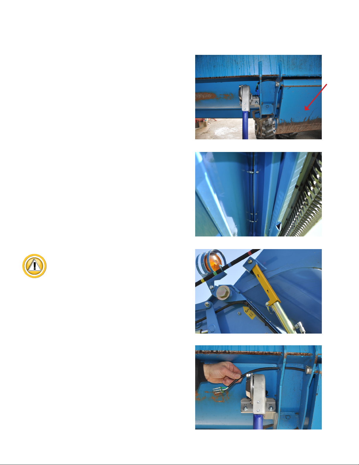
Install Under Mount Wiring (if equipped)
1. Wires must be routed behind the front beam to the
nearest skid (A) before routing back under the header pan
to protect them from crop stubble.
2. Remove the rear bolts from the skid (A) and allow the
back of the skid to hang down to provide access to drill
holes and route wire.
3. It the sensor is not mounted next to a skid, route
harness toward the skid keeping it protected behind the
front beam as shown.
A
If replacing bolts, use jack to raise cover and be
sure to install cylinder stop..
4. Select correct length extension harness.
5. For XCV/XCS heads only, remove Weatherpack
connector and route wire through hole in gusset as shown.
16
6. For older heads route wire above the gusset as shown.
7. Drill 1/4” pilot hole near top of lower tube behind center
of skid. Use 1-1/4 inch hole saw provided in kit BSHEL to
drill out pilot hole. (note: skid shoe has been removed)
8. Route wire into tube and install grommet.
9. For most heads, all harnesses can be routed in lower
tubes to left side of feederhouse.
10. Drill 1/4” pilot hole in lower tube left of feederhouse
opening. Use 1-1/4 inch hole saw provided in kit BSHEL
to drill out pilot hole. Using a wire sh, pull harness to hole
and install grommet.
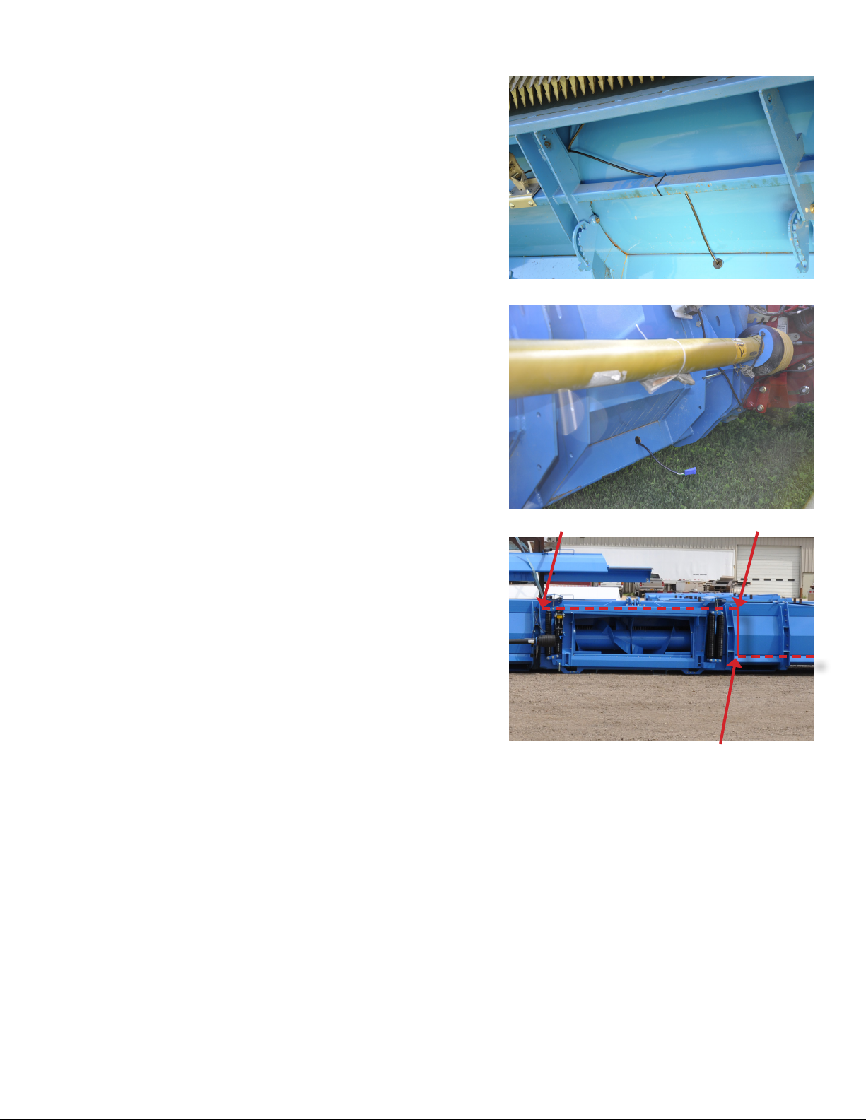
Installation
11. On XCV/XCS models, the lower tube is not open under
the feederbouse.
12. Drill 1-1/4 inch holes at locations A, B, & C and route
wires across the feederhouse in upper tube as indicated.
13. Use a sh tape to pull wires through tube and install
grommets in holes.
14. Zip tie and clamp harness where needed.
A B
C
17

Installation
Install Controller
1. Mount controller bracket to header with hardware
provided in kit B3113.
• Mount controller to bracket
2. Fasten main harness to bracket as shown with zip ties.
• For the rest of the installation instructions see the
supplied Horizon manual for system with Horizon
controller and all others see the supplied combine
manual
18

Sensor Adjustment
Terrace Sensor
Increasing or Decreasing Voltage
1. Loosen the screws indicated A.
2. Turn sensor to new location.
3. Tighten screws A.
Adjusting Voltage Swing
1. Loosen jam nut B.
2. Turn Bolt to adjust.
3. Rotating bolt counter clockwise increases voltage swing
4. Rotating bolt clockwise decreases voltage swing
5. Tighten jam nut B.
Adjusting Down Pressure
1. Loosen jam nut A.
2. Turn bolt to adjust tension.
3. Rotating bolt counter clockwise decreases down
pressure.
4. Rotating bolt clockwise increases down pressure.
5. Tighten jam nut A.
A
A
B
Sensor Adjustment
A
19

Parts
12
3
4
5
6
78
12
3
4
5
6
78
A
26* B7000 BOLT KIT, INCLUDES ITEMS WITH AN ASTERISK*
27 HT7000 COMPLETE SENSOR ASSEMBLY STANDARD
28 HT7001 COMPLETE SENSOR ASSEMBLY FOR SHELBOURNE UNDERMOUNTS
(ASSEMBLY EXCLUDES ITEMS 1, 20, 24, 25, & 26*)
(ASSEMBLY EXCLUDES ITEMS 19, 20, 24, 25, & 26*)
24 HT701-BU LONG WAND, BLUE NYLON 1
25 PFBxx HARNESS (xx - LENGTH IN FT)
LENGTHS: 6, 10, 17, 23, 33, & 38
B
17 08100136 O-RING, SIZE-014 1
18 HT7111 SENSOR ARM 1
19 HT631 CROP DIVIDE TIP 1
20 08200187 M8-1.25x30 SERRATED FLANGE BOLT 2
21 08200249 M8-1.25x55 HEX BOLT 1
22 HT7106 SPRING ADJUSTING CLIP 1
23 08200258 M10-1.5 HEX NUT 1
C
11 HT2128 SENSOR 1
12 08100144 O-RING, SIZE-210 1
13 HT7101 SENSOR BODY 1
14 08100141 BUSHING 1
15 HT7109 BEARING BLOCK 1
16 HT7104 SPRING 1
1
D
10 08200248 M5-0.80x20, SHCS 4
7 HT7105 TRIP BACK SPRING 1
8 HT7116 PIN 1
9 08200247 M10-1.5x30, HEX BOLT 1
3 08100102 5/16 CABLE CLAMP, 3/8 HOLE 2
4 08100132 RETAINING RING 2
5 08200119 M8-1.25, SERRATED FLANGE NUT 2
6 08200246 M8-1.25x45 HEX BOLT 1
E
ITEM NUMBER PART NUMBER DESCRIPTION QUANTITY
1 HT7117 SHIELD 1
2 08200245 M8-1.25x12, SERRATED FLANGE BOLT 3
F
25
G
H
1
NOTE: SENSOR CALIBRATION
TARGET HIGH VOLTAGE = 4.30V (ACCEPTABLE RANGE 4.20V - 4.35V)
TARGET LOW VOLTAGE = 0.70V (ACCEPTABLE RANGE 0.65V - 0.95V)
9
10
21
22
5
23
11
12
24
20
13
4
19
THE INFORMATION CONTAINED ON THIS DRAWING IS PROPRIETARY TO
HEADSIGHT, INC. ANY UNAUTHORIZED USE OF SUCH CONTENTS IS
STRICTLY PROHIBITED.
HT7000_PARTS
TERRACE SENSOR PARTS
HEADSIGHT INC.
Parts
CHG LEVEL
02
C
A
MATERIAL N/A
UNLESS OTHERWISE SPECIFIED
DIMENSIONS ARE IN INCHES
DIMENSIONS W/O TOL ARE BASIC
THIRD ANGLE
PROJECTION
SHEET OF
DATE
AUG 8, 17
1
1
B
C
D
E
14
15
17
F
2
3
4*
3*
6*
5*
7*
8*
16
HT7000_PARTS
18
G
H
20

STATEMENT OF LIMITED WARRANTY
For Headsight® Products
Headsight Inc. (Headsight) warrants its new products to be free from defects in material and workmanship for a period of twelve
(12) consecutive months following the date of purchase by the retail purchaser.
Headsight Inc. (Headsight) warrants its new corn sensors assemblies for a period of thirty-six (36) months.
Headsight warrants genuine Headsight replacement parts and components to be free from defects in material and workmanship
for a period of six (6) consecutive months following the date of purchase or the remainder of the original equipment warranty
period, whichever is longer.
Headsight’s obligation under these warranties shall be limited to repairing or replacing, free of charge to the original purchaser,
any part that, in Headsight’s judgment, shows evidence of such defect.
Limitations to Warranty
This warranty does not cover:
• Warranty claims directly resulting from improper installation of the product.
• Any product damaged by accident, abuse, misuse, or negligence after shipment from Headsight.
• Any unauthorized product alteration or modication.
• Any unauthorized repairs made with parts other than genuine Headsight parts.
• Any repairs performed by anyone other than Headsight or an authorized Headsight dealer unless specically authorized
by Headsight.
Warranty Procedure
• Troubleshooting should be done between farmer/dealer and Headsight through our technical assistance @
574.220.5511.
• Labor reimbursement will occur only pre-arranged through Headsight technical assistance and be scheduled to a at rate
basis or reasonable time allowance in Headsight’s judgment.
• There is no mileage reimbursement.
• Diagnostic time will not be reimbursed except in pre-arranged circumstances.
• Warranty claims should be on typical dealer service work order with a number and name to be attached for any future
correspondence.
• All warranty work must be performed, and claims submitted, within thirty (30) days of the occurrence of the claim and
within the warranty period.
• All parts removed during warranty repair must be returned to Headsight with Headsight’s Return Form within thirty (30)
days of the occurrence of the claim and within the warranty period.
• Headsight, Inc. reserves the right to either inspect the product at the original retail purchaser’s location or require it to be
returned to Headsight, Inc. for inspection.
Limitation of Liability
Headsight makes no express warranties other than those, which are specically described herein. Any description of the goods
sold hereunder, including any reference to buyer’s specications and any descriptions in circulars and other written material
published by Headsight is for the sole purpose of identifying such goods and shall not create an express warranty that the goods
shall conform to such description.
THIS WARRANTY IS EXPRESSLY IN LIEU OF ALL OTHER WARRANTIES EXPRESSED OR IMPLIED. There are no implied
warranties of merchantability or tness of a particular purpose. This warranty states Headsight’s entire and exclusive liability and
buyer’s exclusive remedy or any claim for damages in connection with the sale of furnishing of Headsight products, their design,
suitability for use, installation or operation, or for any claimed defects herein. HEADSIGHT WILL IN NO EVENT BE LIABLE
FOR ANY INCIDENTAL OR CONSEQUENTIAL DAMAGES WHATSOEVER, NOR FOR ANY SUM IN EXCESS OF THE PRICE
RECEIVED FOR THE GOODS FOR WHICH LIABILITY IS CLAIMED.
No representative of Headsight nor any dealer associated with Headsight has the authority to change the items of this warranty
in any manner whatsoever, and no assistance to purchaser by Headsight in the repair of operation of any Headsight product
shall constitute a waiver of the conditions of this warranty, nor shall such assistance extend or revive it.
Headsight reserves the right to make improvements in design or changes in specications at any time, without incurring any
obligation to owners of units previously sold. Warranty: 1/2017
21

P 574.546.5022 • F 574.546.5760
4845 3B Rd • Bremen, IN 46506
info@headsight.com
www.headsight.com
 Loading...