

Page 1

HEADSIGHT.COM I 574.546.5022
Terrahawk
Model HT5200
Operations and Settings
090xxxxxa
Page 2

i
Notices for Operation of Terrahawk in the US
Note: This equipment has been tested and found to comply with the limits for a Class A digital
device, pursuant to part 15 of the FCC Rules. These limits are designed to provide reasonable
protection against harmful interference when the equipment is operated in a commercial
environment. This equipment generates, uses, and can radiate radio frequency energy and, if
not installed and used in accordance with the instruction manual, may cause harmful
interference to radio communications. Operation of this equipment in a residential area is
likely to cause harmful interference in which case the user will be required to correct the
interference at his own expense.
THIS DEVICE COMPLIES WITH PART 15 OF THE FCC RULES. OPERATION IS SUBJECT TO THE
FOLLOWING TWO CONDITIONS.
(1) THIS DEVICE MAY NOT CAUSE HARMFUL INTERFERENCE, AND
(2) THIS DEVICE MUST ACCEPT ANY INTERFERENCE RECEIVED, INCLUDING
INTERFERENCE THAT MAY CAUSE UNDESIRED OPERATION.
Warning: Changes or modifications not expressly approved by the party responsible for
compliance could void the user’s authority to operate this equipment.
IMPORTANT NOTE: This device is considered a UWB imaging device and is subject to FCC
Coordination requirements under the CFR Tile 47 Chapter I, Sub chapter A, Part 15, Subpart F
, Section 15.525. As such it is the responsibility of the users of these systems to submit the
following information to the FCC prior to use of these systems. The users of UWB imaging
devices shall supply operational areas to the FCC Office of Engineering and Technology, which
shall coordinate this information with the Federal Government through the National
Telecommunications and Information Administration. The information provided by the UWB
operator shall include the name, address and other pertinent contact information of the user,
the desired geographical area(s) of operation, and the FCC ID number and other nomenclature
of the UWB device. If the imaging device is intended to be used for mobile applications, the
geographical area(s) of operation may be the state(s) or county(ies) in which the equipment
will be operated. The operator of an imaging system used for fixed operation shall supply a
specific geographical location or the address at which the equipment will be operated. This
material shall be submitted to Frequency Coordination Branch, OET, Federal Communications
Commission, 445 12th Street, SW, Washington, D.C. 20554, Attn: UWB Coordination. The
operator shall comply with any constraints on equipment usage resulting from this
coordination.
Notes:
The device is to be used for agricultural purposes, at a height of one meter above crop heights,
but not to exceed 12 feet (3.7 meters) above the soil surface.
Multiple Terrahawk transmitters intended to be mounted on a single piece of farming machinery
(a combine harvester, ground tiller, fertilizer, etc.) in any installation shall be positioned for
operation with a minimum separation distance of 1.5 m (~ 5 feet) between transmitters.
The Terrahawk’s emissions shall be aimed downward toward the ground so they can be
attenuated by the presence of crops, and shall not be operated at a height of greater than 1
meter when there are no crops beneath the device.
The Terrahawk shall only be installed on farming machinery (combine harvesters, ground tillers,
fertilizers, etc.) and operated in fields that are located in rural or predominantly agricultural areas
as generally defined by the United States Geological Survey National Land Cover Database
(NLCD) classifications 81 (Pasture/Hay) and 82 (Cultivated Crops).
Operation of this device shall be limited to parties eligible for licensing under the provisions of
part 90 of the Commission’s rules (e.g., persons regularly involved in activities such as the
operation of farms, ranches, or similar land areas, for the quantity production of crops or plants;
including soil plowing, soil conditioning, seeding, fertilizing, or harvesting for agricultural
activities). No operation in city gardens or on trees is permitted.
Terrahawk devices used in the US must be coordinated with the FCC prior to use. A coordination
postcard was included in the front of this manual for your convenience.
Page 3

ii
Notices for Operation of Terrahawk in Canada
This device complies with Industry Canada licence-exempt RSS standard(s).
Operation is subject to the following two conditions: (1) this device may not cause
interference, and (2) this device must accept any interference, including interference
that may cause undesired operation of the device.
Le présent appareil est conforme aux CNR d'Industrie Canada applicables aux
appareils radio exempts de licence. L'exploitation est autorisée aux deux conditions
suivantes : (1) l'appareil ne doit pas produire de brouillage, et (2) l'utilisateur de
l'appareil doit accepter tout brouillage radioélectrique subi, même si le brouillage est
susceptible d'en compromettre le fonctionnement.
Under Industry Canada regulations, this radio transmitter may only operate using an
antenna of a type and maximum (or lesser) gain approved for the transmitter by
Industry Canada. To reduce potential radio nterference to other users, the antenna
type and its gain should be so chosen that the equivalent isotropically radiated power
(e.i.r.p.) is not more than that necessary for successful communication.
Conformément à la réglementation d'Industrie Canada, le présent émetteur radio
peut fonctionner avec une antenne d'un type et d'un gain maximal (ou inférieur)
approuvé pour l'émetteur par Industrie Canada. Dans le but de réduire les risques de
brouillage radioélectrique à l'intention des autres utilisateurs, il faut choisir le type
d'antenne et son gain de sorte que la puissance isotrope rayonnée équivalente
(p.i.r.e.) ne dépasse pas l'intensité nécessaire à l'établissement d'une communication
satisfaisante.
This equipment complies with the ICES RF radiation exposure limits set forth for an
uncontrolled environment. This equipment should be installed and operated with a
minimum distance of 20cm between the radiator and any part of the human body.
Cet équipement est conforme aux limites d'exposition aux radiations ICES définies
pour un environnement non contrôlé . Cet équipement doit être installé et utilisé à
une distance minimale de 20 cm entre le radiateur et une partie de votre corps.
Note: This Ground Penetrating Radar Device shall be operated only when directed at
the ground within one meter of the surface under analysis.
Remarque: Ce dispositif de radar à pénétration au sol ne doit être utilisé que
lorsqu'il est dirigé vers le sol à moins d'un mètre de la surface en analyse.
Note: This Ground Penetrating Radar Device shall only be operated for purposes
associated with the agricultural industry.
Remarque: Cet appareil de radar à pénétration au sol ne doit être utilisé qu'à des
fins associées à l'industrie agricole.
Page 4
iii
About Headsight
Headsight Contact Info
Headsight, Inc
Bremen, IN 46506
Phone: 574-546-5022
Fax: 574-546-5760
Email: [email protected]
Web: www.headsight.com
Technical Assistance
Phone: 574-220-5511
About this Manual
How to use this manual
For new installations, follow all applicable instructions in each of the
numbered sections (1, 2, etc) in the order that they are presented in this manual.
The information in the lettered appendices (A, B, etc) is for service or advanced
settings which you will not need for most installations, but may want to reference
in the future.
This icon designates information of which you should take note.
This icon designates an important instruction.
Disclaimers
Headsight®, Horizon®, Pinpoint®, Insight®, Foresight®, Feathersight®,
Truesense™ and Truesight® are trademarks of Headsight, Inc. All other
trademarks are property of their respective owners.
Suggestions
If you have any suggestions to improve this manual –please call 574-546-5022 or
email [email protected].
Portions of this product are protected by US Patents 6202395, 6833299,
7310931, 7647753 and other US and international patents, issued and
pending.
Copyright Headsight, Inc. 2016
Page 5

4
Table of Contents
About Headsight iii
Headsight Contact Info iii
Technical Assistance iii
About this Manual iii
How to use this manual iii
Disclaimers iii
Suggestions iii
1. Theory of Operation 5
2. Sensor Power and Status 6
2.1. Powering the Terrahawk sensors 6
2.2. Sensor light Status 6
3. Setup 7
3.1. System Setup 7
3.2. Assigning Sensors 7
3.3. Range 8
3.4. Offset 9
3.5. OSD / ISD 10
3.5.1. Theory of Operation 10
3.5.2. Setting OSD and ISD 10
4. Operation 12
Page 6
5
1. Theory of Operation
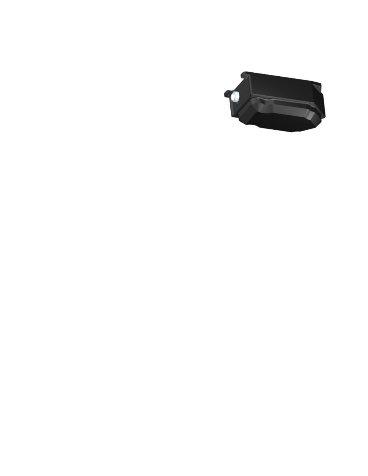
The Terrahawk ground penetrating radar sensor
is designed to mount on the header of an
agricultural harvester to measure the distance to
the ground and/or crop. This data may be used
for header control as well as logged for analysis.
Sensors should be mounted in accordance with
the installation manual for the specific header
being used.
Terrahawk sensors are connected through a CAN bus on the header to a
Horizon base controller mounted on the header near the single point connection.
The user interface for the Horizon base controller is generally an OEM or
aftermarket UT in the cab of the combine. This manual explains the operation
and settings for the Terrahawk units through Horizon interface on the UT.
Page 7

6
2. Sensor Power and Status
2.1. Powering the Terrahawk sensors
1. Terrahawk sensors are powered by connecting them to the Horizon
header CAN network.
2. The Horizon CAN network is tied to key power so the sensors are emitting
when the machine is keyed on.
2.2. Sensor light Status
The LED near the connector of the sensor indicates its status.
1. Flashing green – active, emitting and receiving signal
Page 8
7
3. Setup
3.1. System Setup
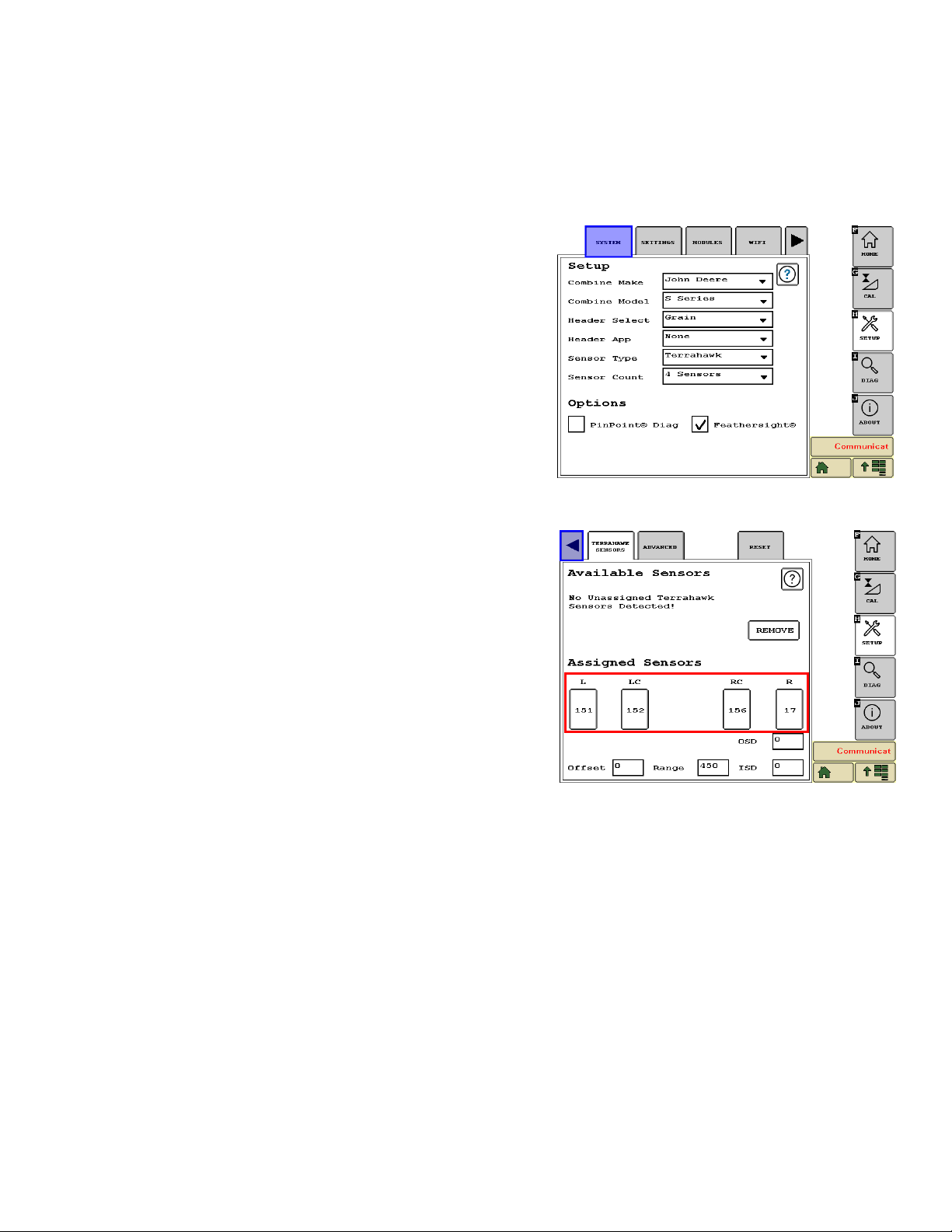
1. On the UT interface in the cab, open the
Horizon pool, and press the “Setup”
softkey on the right.
2. Press the “System” tab along the top.
3. Input the information of your combine and
header.
a. For Sensor type select
“Terrahawk”
b. Check “Feathersight” if you have a
platform head and plan to run near
the ground
3.2. Assigning Sensors
1. On the UT interface in the cab, open the
Horizon pool, and press the “Setup”
softkey on the right.
2. Scroll over in the tabs along the top and
press “Terrahawk Sensors”.
3. The sensor locations are displayed on the
screen and the last 3 digits of each
sensor serial number are display on the
sensor icon. The location of these serial
numbers must match the actual location
of the sensors on the head.
4. Horizon has the ability to read the serial
number of each Terrahawk sensor but cannot tell the location of the
sensors on the head. During initial setup of the system, it will guess that
the sensor with the lowest serial number is on the left and that each
sensor position moving across the head to the right has a higher serial
number.
5. If two serial numbers are in the wrong place, simply press the icons of the
two incorrect sensors on the screen and the serial numbers will be
swapped.
Page 9

8
3.3. Range
1. On the UT interface in the cab, open the
Horizon pool, and press the “Setup”
softkey on the right.
2. Scroll over in the tabs along the top and
press “Terrahawk Sensors”.
3. The range setting specifies the allowable
range of operation (min to max cut height)
in millimeters. 450mm (18 inches) often
works well.
4. Increasing the “Range” value gives a
larger allowable range of cut height but
reduces the amount of sensitivity within
the range.
5. Decreasing the “Range” value gives a
smaller allowable range of cut height but
increases the amount of sensitivity within
the range.
Page 10
9
3.4. Offset
6. On the UT interface in the cab, open the
Horizon pool, and press the “Setup”
softkey on the right.
7. Scroll over in the tabs along the top and
press “Terrahawk Sensors”.
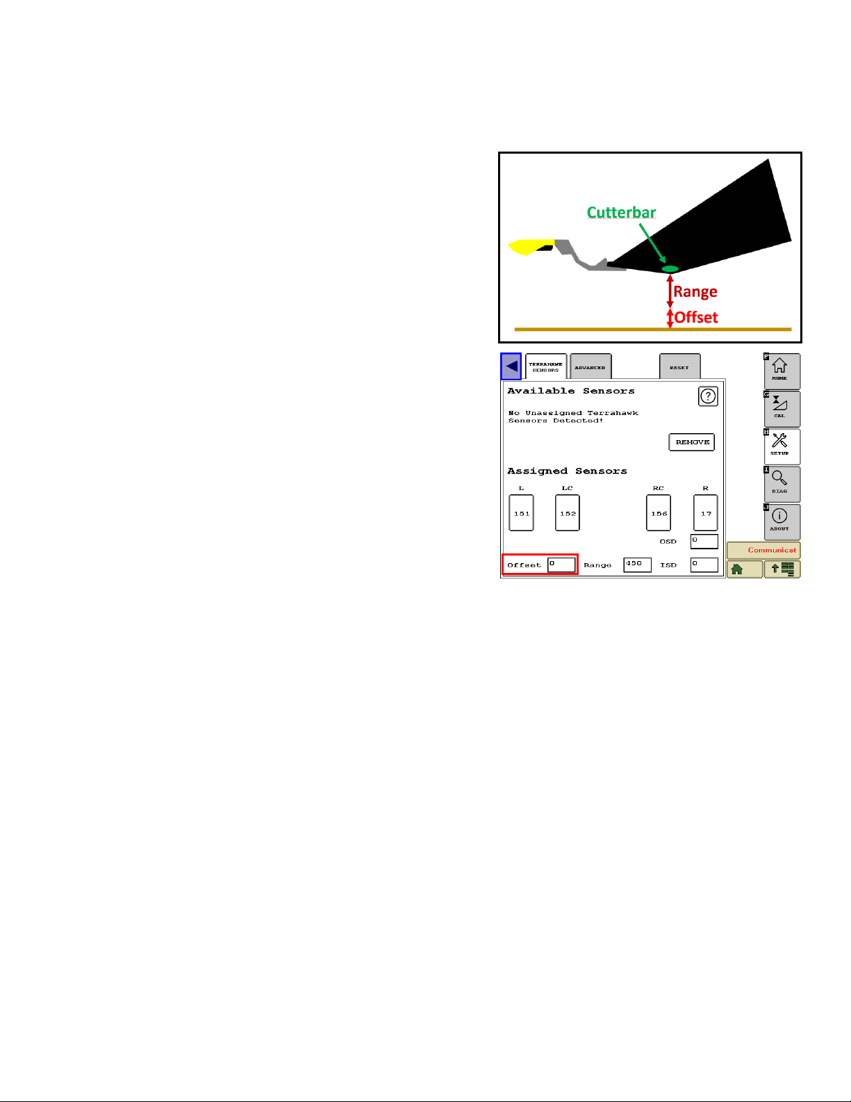
1. After setting the range, an offset can be
added if needed. The offset is input in
millimeters and is used to shift the range
up from the ground. This allows you to
increase cut height without increasing the
range (since increasing the range will
decrease the sensitivity).
2. The default value for offset is 0 and if your
desired cut height is within 18 inches of
the ground, it is probably fine to leave it
there.
3. By definition, the offset value is raising the
bottom end of the operating range - so if
you add an offset, you will no longer be
able to cut at the ground.
4. The combine will perform the best if you
use an offset value that allows you to cut
in the center of the combines height
range.
5. Since having an offset value means you cannot cut close to the ground
the Feathersight option must be turned off (“Setup” softkey, “System” tab).
Page 11
10
3.5. OSD / ISD
3.5.1. Theory of Operation
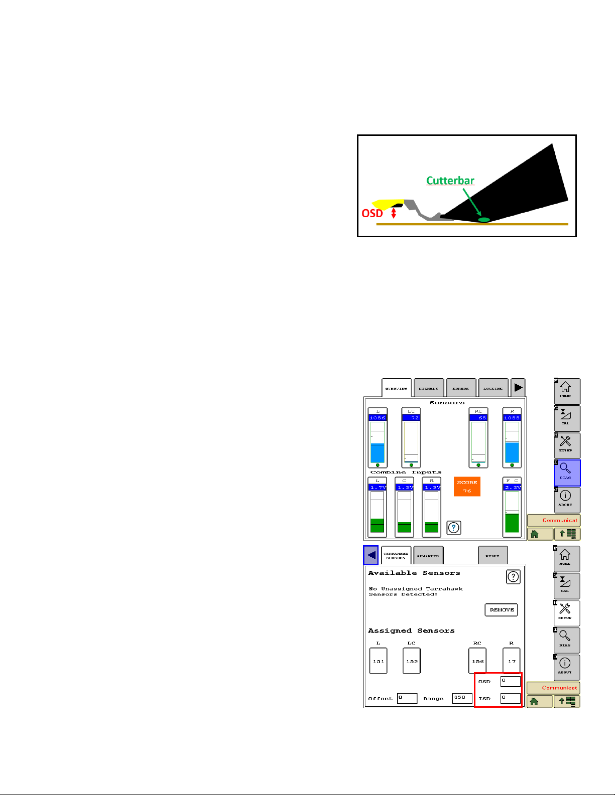
1. It is difficult for a Terrahawk sensor to
see things that are very close to it.
Sometimes the sensor will see
something (or think it sees something) in
its very near field vision. The sensor is
most responsive to things that are close
to it, so when this happens it tends to
overreact and quickly raise the header
out of the crop. OSD and ISD stand for “Outer Start Distance” and “Inner
Start Distance” respectively. This is the start distance where the sensor
will begin looking so if something comes closer to the sensor than this
value, the sensor will ignore it. Properly setting OSD and ISD can
significantly improve the stability of the header control. OSD and ISD
should be set as large as possible without missing values (representing
objects) that are critical.
3.5.2. Setting OSD and ISD
1. Set the header on the ground.
2. On the UT interface in the cab, open the
Horizon pool, and press the “Diagnostic”
softkey on the right.
3. Select the “Overview” tab along the top.
4. If all sensors are mounted under the head,
the reading of each sensor should be
approximately the same. In the screen
shot shown, the outer sensors are raised
terrace mounts out in front of the end
dividers so the value of the outer sensors
is much higher.
5. First set the ISD. Since the header is
resting on the ground, the value of the
inner sensors should theoretically never
go below 65 if the ground is level.
However, the purpose of the sensor it to
read variance in the ground so a good
setting might be 35. This is 30 mm less
than the bottom of the range meaning that
if the head is all the way on the ground
and there is a 30mm variance in the
ground from one radar reading to the next
(a very short time ) the radar should be
Page 12

11
able to see it.
6. Next set the OSD. The same principle applies, the lowest value in the
example is 1056. Since these sensors are farther out in front of the
combine, there could likely be more variance so a good value for OSD
would probably be around 1000.
Page 13

12
4. Operation
1. Be sure initial settings have been entered and Horizon has been
calibrated.
2. Calibrate the Header to the combine per combine operator’s manual.
3. Operate the Headsight Height control system the same as an OEM
combine height control system.
4. Fine tune all combine speed and sensitivity adjustments for best
performance.
Page 14
13
Page 15

14
This page is intentionally left blank.
Page 16

15
 Loading...