

Page 1

TECHNICAL MANUAL
OPERATOR’S MANUAL
ARMY MODEL OH-58A/C
HELICOPTER
TM 55-1520-228-10
This manual supersedes TM 55-1520-228-10 and TM 55-1520236-10, 7 April 1978, including all changes.
HEADQUARTERS, DEPARTMENT OF THE ARMY
17 JANUARY 1989
Page 2

Page 3
TM 55-1520-228-10
WARNING
An operating procedure, practice, etc., which, if not correctly followed, could result in personnel injury or
loss of life.
An operating procedure, practice, etc., which, if not strictly observed, could result in damage to or destruction
of equipment.
NOTE
An operating procedure, condition, etc., which it is essential to highlight.
WARNING
PRECAUTIONARY DATA
Personnel performing operations, procedures and practices which are included or implied in this technical manual
shall observe the following warnings. Disregard of
injury or loss of life.
these warnings or precautionary information can cause serious
WARNING
STARTING ENGINE
Coordinate all cockpit actions with ground observer. Ensure that rotors and blast areas are clear and fire guard is
posted, if available.
WARNING
FIRE EXTINGUISHER
Exposure to high concentrations of monobromotribluoromethane (CF Br) extinguishing agent or toxic fumes produced by the agent should be avoided. Th
cause frostbite or low temperature burns.
e liquid should not be allowed to come into contact with the skin, as it may
WARNING
GROUND OPERATION
Engines will be started and ope
rated only by authorized personnel. Reference AR 95–1.
WARNING
ELECTROLYTE
Battery electrolyte is harmful to the skin and clothing. Neutralize any spilled electrolyte by flushing contacted areas
thoroughly with water.
Change 12 a
Page 4
TM 55-1520-228-10
When smoke, suspected carbon monoxide fumes, or symptoms of anoxia exist, the crew s
immediately ventilate cabin and shut off heater.
Turbine fuels and lubricating oil contain additives which are poisonous and readily absorbed through
the skin. Do not allow them to remain on skin longer than necessary.
Prolonged contact with liquid or mist can irritate eyes and skin. After prolonged contact with skin,
immediately wash contacted area with soap and water. If liquid
with clean water. If liquid is swallowed, do not induce vomiting; get immediate medical attention.
Wear rubber gloves when handling liquid. If prolonged contact with mist is likely, wear an appropriate respirator. When fluid is decomposed by heating, t
CARBON MONOXIDE
hould
HANDLING FUEL AND OILS
HANDLING HYDRAULIC FLUID (MIL-H-83282)
contacts eyes, flush immediately
oxic gases are released.
HAZARDOUS CARGO
Items of cargo possessing dangerous physical pr
etc., must be handled with extreme caution and in accordance with established regulations. Refer
to TM 38-250.
Sound pressure levels in this aircraft during some operating conditions exceed the Surgeon General’s hearing conservation criteria as defined in TB MED 501. Hearing protection devices, such as
the aviator helmet or earplugs are require
during its operation.
d to be worn by all personnel in and around the aircraft
operties, such as explosives, acids
NOISE
, fl ammable,
b Change 14
Page 5
Page 6

Page 7

TM 55-1520-228-10
C 14
CHANGE HEADQUARTERS
No. 14 DEPARTMENT OF THE ARMY
WASHINGTON, D.C.,
TECHNICAL MANUAL
31 March 2006
OPERATOR’S MANUAL
ARMY MODEL OH-58/AC
HELICOPTER
DISTRIBUTION STATEMENT A:
TM 55-1520-228-10, 17 January 1989, is changed as follows:
1. Remove and insert pages as indicated below. New or changed text material is indicated by a vertical
bar in the margin. An illustration change is indicated by a miniature pointing hand.
Remove Pages Insert Pages
a and b a and b
A and B A and B
2-1 through 2-4 2-1 through 2-4
2-7 through 2-10 2-7 through 2-10
2-13 and 2-14 2-13 and 2-14
2-23 and 2-24 2-23 and 2-24
2-29 and 2-30 2-29 and 2-30
2-35 through 2-38 2-35 through 2-38
2-46.1 and 2-46.2 2-46.1 and 2-46.2
2-49 through 2-52 2-49 through 2-52
2-57 and 2-58 2-57 and 2-58
3-3 and 3-4 3-3 and 3-4
5-1 and 5-2 5-1 and 5-2
(5-3 blank)/5-4 through 5-12 (5-3 blank)/5-4 through 5-12
6-1 and 6-2 6-1 and 6-2
8-5 through 8-8 8-5 through 8-8
8-11 through 8-14 8-11 through 8-14
9-1 through 9-13/(9-14 blank) 9-1 through 9-13/(9-14 blank)
Approved for public release; distribution is unlimited.
2. Retain this sheet in front of manual for reference purposes.
Page 8

TM 55-1520-228-10
C14
By Order of the Secretary of the Army:
Official:
JOYCE E. MORROW
Administrative Assistant to the
Secretar
y of the Army
0528701
DISTRIBUTION:
To be distributed in accordance with Initial Distribution Number
TM 55-1520-228-10.
PETER J. SCHOOMAKER
General, United States Army
Chief of Staff
(IDN) 310230 requirements for
Page 9

TM 55-1520-228-10
y
C13
CHANGE HEADQUARTERS
NO. 13 DEPARTMENT OF THE ARMY
WASHINGTON, D.C., 30 August 2005
TECHNICAL MANUAL
OPERATOR’S MANUALS
ARMY MODEL OH-58A/C
HELICOPTER
DISTRIBUTION STATEMENT A: Approved for public release; distribution is unlimited.
TM 55-1520-228-10, dated 17 January 1989, is changed as follows:
1. Remove and insert pages as indicated below. New or changed text material is indicated by a
vertical bar in the margin. An illustration change is indicated by a miniature pointing hand.
Remove Pages Insert Pages
A and B A and B
2-11 and 2-12 2-11 and 2-12
(5-3 blank) and 5-4 (5-3 blank) and 5-4
2. Retain this sheet in front of manual for reference purposes.
By Order of the Secretary of the Army:
Official:
PETER J. SCHOOMAKER
General, United States Army
Chief of Staff
SANDRA R. RILEY
Administrative Assistant to the
Secretar
of the Army
0519202
DISTRIBUTION: To be distributed in accordance with Initial Distribution Number (IDN) 310230,
requirements for TM 55-1520-228-10.
Page 10

Page 11

TM 55-1520-228-10
C 12
CHANGE HEADQUARTERS
DEPARTMENT OF THE ARMY
NO. 12 WASHINGTON, D.C., 10 June 2005
TECHNICAL MANUAL
OPERATOR’S MANUAL
ARMY MODEL OH-58/AC
HELICOPTER
DISTRIBUTION STATEMENT A: Approved for public release; distribution is unlimited.
TM 55-1520-228-10, 17 January 1989, is changed as follows:
1. Remove and insert pages as indicated below. New or changed text material is indicated by a vertical
bar in the margin. An illustration change is indicated by a miniature pointing hand.
Remove Pages Insert Pages
a and b a and b
A and B A and B
2-1 through 2-12 2-1 through 2-12
2-27 and 2-28 2-27 and 2-28
2-37 and 2-38 2-37 and 2-38
2-43 and 2-44 2-43 and 2-44
2-49 through 2-52 2-49 through 2-52
2-55 through 2-60 2-55 through 2-60
2-63 and 2-64 2-63 and 2-64
(5-3 blank)/ 5-4 (5-3 blank)/ 5-4
7-79 and 7-80 7-79 and 7-80
8-7 and 8-8 8-7 and 8-8
9-7 and 9-8 9-7 and 9-8
2. Retain this sheet in front of manual for reference purposes.
By Order of the Secretary of the Army:
Official:
SANDRA R. RILEY
Administrative Assistant to the
Secretar
DISTRIBUTION: To be distributed in accordance with Initial Distribution Number (IDN) 310230,
requirements for TM 55-1520-228-10.
y of the Army
0512202
PETER J. SCHOOMAKER
General, United States Army
Chief of Staff
Page 12

Page 13

TM 55-1520-228-10
C11
CHANGE HEADQUARTERS
DEPARTMENT OF THE ARMY
NO. 11 WASHINGTON, D.C. 1 April 2003
TECHNICAL MANUAL
OPERATOR’S MANUAL
ARMY MODEL OH-58A/C
HELICOPTER
DISTRIBUTION STATEMENT A: Approved for public release; distribution is unlimited.
TM 55-1520-228-10, 17 January 1989, is changed as follows:
1. Remove and insert pages as indicated below . New or changed text material is indicated by a vertical bar in the
margin. An illustration change is indicated by a miniature pointing hand.
Remove pages Insert pages
a and b a and b
A and B A and B
i through iv i through iv
1-1 and 1-2 1-1 and 1-2
2-1 through 2-4 2-1 through 2-4
2-11 through 2-14 2-11 through 2-14
2-17 through 2-20 2-17 through 2-20
2-23 through 26 2-23 through 2-26
2-27 through 2-30 2-27 through 2-30
2-33 and 2-34 2-33 and 2-34
2-43 and 2-44 2-43 and 2-44
2-46.1 through 2-54 2-46.1 through 2-54
2-57 and 2-58 2-57 and 2-58
2-61 through 2-67(2-68 blank) 2-61 through 2-67(2-68 blank)
3-1 through 3-8.1/(3-8.2 blank) 3-1 through 3-8.2
– – – – – – 3-8.3 and 3-8.4
3-11 through 3-14 3-11 through 3-14
3-17 through 3-20 3-17 through 3-20
3-23 through 3-24.1/ (3-24.2 blank) 3-23 through 3-24.1/ (3-24.2 blank)
3-27 and 3-28 3-27 and 3-28
3-31 through 3-32.2 3-31 through 3-32.2
– – – – – – (3-32.3 blank)/ and 3-32.4
3-33 through 3-36 3-33 through 3-36
5-1 through 5-10 5-1 through 5-10
6-1 through 6-7/(6-8 blank) 6-1 through 6-7/(6-8 blank)
7-1 through 7-6 7-1 through 7-6
7-59 through 7-62 7-59 through 7-62
7-79 and 7-80 7-79 and 7-80
Page 14

TM 55-1520-228-10
C11
Remove pages Insert pages
7-81/(7-82 blank) – – – – – –
(7-83 blank)/7-84 (7-83 blank)/7-84
8-1 through 8-12 8-1 through 8-12
8-15 through 8-17/(8-18 blank) 8-15 through 8-17/(8-18 blank)
9-1 and 9-2 9-1 and 9-2
9-7 and 9-8 9-7 and 9-8
9-11 through 9-14 9-11 through 9-14
A-1/(A-2 blank) A-1 and A-2
Index-1 through Index-9/(Index-10 blank) Index-1 through Index-9/(Index-10 blank)
2. Retain this sheet in front of manual for reference purposes.
By Order of the Secretary of the Army:
Official:
ERIC K. SHINSEKI
General, United States Army
Chief of Staff
JOEL B. HUDSON
Administrative Assistant to the
Secretary of the Army
0304901
DISTRIBUTION:
To be distributed in accordance with Initial Distribution Number (IDN) 310230, requirements for
TM 55-1520-228-10.
Page 15

TM 55-1520-228-10
C10
CHANGE HEADQUARTERS
DEPARTMENT OF THE ARMY
NO. 10 WASHINGTON, D.C., 28 July 2000
TECHNICAL MANUAL
OPERATOR'S MANUAL
ARMY MODEL OH-58A/C
HELICOPTER
DISTRIBUTION STATEMENT A: Approved for public release; distribution is unlimited.
TM 55-1520-228-10, 17 January 1989, is changed as follows:
1. Remove and insert pages as indicated below. New or changed text material is indicated by vertical bar in the margin.
An illustration change is indicated by a miniature pointing hand.
Remove Pages Insert Pages
a and b a and b
A/(B blank) A and B
i through iv i through iv
1-1 and 1-2 1-1 and 1-2
2-3 through 2-12 2-3 through 2-12
2-17 and 2-18 2-17 and 2-18
2-21 and 2-22 2-21 and 2-22
----------- 2-22.1/(2-22.2 blank)
2-23 and 2-24 2-23 and 2-24
----------- 2-26.1 and 2-26.2
2-27 through 2-36 2-27 through 2-36
2-39 through 2-44 2-39 through 2-44
2-49 and 2-50 2-49 and 2-50
2-55 and 2-56 2-55 and 2-56
2-63 and 2-64 2-63 and 2-64
2-65/(2-66 blank) 2-65 and 2-66
------------ 2-67/(2-68 blank)
3-1 through 3-4 3-1 through 3-4
3-7 and 3-8 3-7 and 3-8
------------ 3-8.1/(3-8.2 blank)
3-23 and 3-24 3-23 and 3-24
3-24 1/(3-24.2 blank) 3-24.1/(3-24.2 blank)
3-25 through 3-30 3-25 through 3-30
3-33/(3-34 blank) 3-33 through 3-36
------------- 3-37/(3-38 blank)
4-1 though 4-20 4-1/(4-2 blank)
Page 16

TM 55-1520-228-10
C10
Remove Pages Insert Pages
5-1 and 5-2 5-1 and 5-2
5-3 and 5-4 (5-3 blank) /5-4
5-5 through 5-12 5-5 through 5-12
6-1 through 6-6 6-1 through 6-6
6-7 and 6-8 6-7/(6-8 blank)
6-9/(6-10 blank) 6-9/(6-10 blank)
7-1 through 7-4 7-1 through 7-4
7-7 through 7-14 7-7 and 7-8
7-15/(7-16 blank) ---------7-17 through 7-46 ---------7-55 and 7-56 7-55 and 7-56
7-59 through 7-62 7-59 through 7-62
7-77 and 7-78 7-77 and 7-78
8-3 through 8-8 8-3 through 8-8
----------- 8-8.1/(8-8 2 blank)
8-9 through 8-16 8-9 through 8-16
8-17/(8-18 blank) 8-17/(8-18 blank)
9-1 and 9-2 9-1 and 9-2
9-7 through 9-10 9-7 through 9-10
9-13 and 9-14 9-13/(9-14 blank)
9-15/(9-16 blank) 9-15/(9-16 blank)
A-1/(A-2 blank) A-1/(A-2 blank)
Index-1 through Index-8 Index-1 through Index-8
Index-9/(Index-10 blank) Index-9/(Index-10 blank)
2. Retain this sheet in front of manual for reference purposes.
By Order of the Secretary of the Army:
Official:
ERIC K. SHINSEKI
General, United States Army
Chief of Staff
JOEL B. HUDSON
Administrative Assistant to the
Secretary of the Army
.
0011522
DISTRIBUTION: To be distributed in accordance with Initial Distribution Number (IDN) 310230, requirements for
TM 55-1520-228-10.
Page 17

URGENT
TM 55-1520-228-10
C 9
CHANGE
NO. 9
DEPARTMENT OF THE ARMY
WASHINGTON, D.C., 18 July 1997
HEADQUARTERS
Operator"s Manual
ARMY MODEL OH-58A/C HELICOPTER
DISTRIBUTION STATEMENT A:
TM 55-1520-228-10, 17 January 1989, is changed as follows:
1.
Remove and insert pages as indicated below. New or changed text material is indicated by
vertical bar in the margin. An illustration change is indicated by a miniature pointing hand.
Remove pages
2-33 and 2-34
3-23 and 3-24
3-31 and 3-32
8-5 and 8-6
Approved for public release; distribution is unlimited
Insert pages
2-33 and 2-34
3-23 and 3-24
3-24.1/(3-24.2 blank)
3-31 and 3-32
3-32.1 and 3-32.2
8-5 and 8-6
2.
Retain this sheet in front of manual for reference purposes.
By Order of the Secretary of the Army:
DENNIS J. REIMER
General, United States Army
Chief of Staff
Administrative Assistant to the
Secretary of the Army
03872
DISTRIBUTION:
To be distributed in accordance with DA Form 12-31-E, block no. 0230, requirements for
TM 55-1520-228-10.
Page 18

Page 19
Page 20
Page 21
Page 22

Page 23
Page 24

Page 25

TM 55-1520-228-10
C 5
URGENT
CHANGE HEADQUARTERS
DEPARTMENT OF THE ARMY
NO. 5 WASHINGTON, D.C., 22 July 1991
Operator’s Manual
ARMY MODEL OH-58A/C HELICOPTER
TM 55-1520-228-10, 17 January 1989, is changed as follows:
1. Remove and insert pages as indicated below. New or changed text material is indicated by a vertical bar in the
margin. An illustration change is indicated by a miniature pointing hand.
Remove pages Insert pages
3-27 and 3-28 3-27 and 3-28
5-11 and 5-12 5-11 and 5-12
8-17/8-18 8-17/8-18
2. Retain this sheet in front of manual for reference purposes.
By Order of the Secretary of the Army:
GORDON R. SULLIVAN
General, United States Army
Official:
PATRICIA P. HICKERSON
Chief of Staff
Colonel, United States Army
The Adjutant General
DISTRIBUTION:
To be distributed in accordance with DA Form 12-31-E, block no. 0230, -10 and CL maintenance requirements for TM
55-1520-228-10.
URGENT
Page 26

Page 27

TM 55-1520-228-10
URGENT C4
CHANGE HEADQUARTERS
DEPARTMENT OF THE ARMY
NO. 4 WASHINGTON, D.C., 31 July 1990
Operator’s Manual
ARMY MODEL OH-58A/C HELICOPTER
TM 55-1520-228-10, 17 January 1989, is changed as follows:
1. Remove and insert pages as indicated below. New or changed text material is indicated by a vertical bar in the
margin. An illustration change is indicated by a miniature pointing hand.
Remove pages Insert pages
2-21 and 2-22 2-21 and 2-22
2-45 and 2-46 2-45 and 2-46
2-46.1 and 2-46.2
3-23 and 3-24 3-23 and 3-24
3-25 and 3-26 3-25 and 3-26
2. Retain this sheet in front of manual for reference purposes.
By Order of the Secretary of the Army:
CARL E. VUONO
General, United States Army
Official:
WILLIAM J. MEEHAN II
Chief of Staff
Brigadier General, United States Army
The Adjutant General
DISTRIBUTION:
To be distributed in accordance with DA Form 12-31, -10 and CL Maintenance requirements for OH-58A and OH-58C
Helicopter, Observation.
URGENT
Page 28

Page 29

URGENT TM 55-1520-228-10
C 3
CHANGE HEADQUARTERS
DEPARTMENT OF THE ARMY
NO. 3 WASHINGTON, D.C., 6 March 1990
Operator’s Manual
ARMY MODEL OH-58A/C HELICOPTER
TM 55-1520-228-10, 17 January 1989, is changed as follows:
1. Remove and insert pages as indicated below. New or changed text material is indicated by a vertical bar in the
margin. An illustration change is indicated by a miniature pointing hand.
Remove pages Insert pages
6-7 and 6-8 6-7 and 6-8
2. Retain this sheet in front of manual for reference purposes.
By Order of the Secretary of the Army:
CARL E. VUONO
General, United Stages Army
Official:
Chief of Staff
WILLIAM J. MEEHAN II
Brigadier General, United States Army
The Adjutant General
DISTRIBUTION:
To be distributed in accordance with DA Form 12-31, -10 and CL Maintenance requirements for OH-58A and OH-58C
Helicopter, Observation.
URGENT
Page 30

Page 31

URGENT
NOTICE: THIS CHANGE HAS BEEN PRINT ED AND DISTRIBUT ED OUT OF SEQUENCE. IT SHOULD BE INSERT ED
IN THE MANUAL AND USED. UPON RECEIPT OF THE EARLIER SEQUENCED CHANGE INSURE A MORE
CURRENT CHANGE PAGE IS NOT REPLACED WITH A LESS CURRENT PAGE.
TM 55-1520-228-10
C 2
CHANGE HEADQUARTERS
DEPARTMENT OF THE ARMY
NO. 2 WASHINGTON, D.C., 11 October 1989
Operator’s Manual
ARMY MODEL OH-58A/C HELICOPTER
TM 55-1520-228-10, 17 January 1989, is changed as follows:
1. Remove and insert pages as indicated below. New or changed text material is indicated by a vertical bar in the
margin. An illustration change is indicated by a miniature pointing hand.
Remove pages Insert pages
5-11 and 5-12 5-11 and 5-12
8-13 and 8-14 8-13 and 8-14
2. Retain this sheet in front of manual for reference purposes.
By Order of the Secretary of the Army:
CARL E. VUONO
General, United States Army
Official:
WILLIAM J. MEEHAN II
Chief of Staff
Brigadier General, United States Army
The Adjutant General
DISTRIBUTION:
To be distributed in accordance with DA Form 12-31, -10 and CL Maintenance requirements for OH-58A and OH-58C
Helicopter, Observation.
URGENT
Page 32

Page 33

TM 55-1520-228-10
C 1
CHANGE HEADQUARTERS
DEPARTMENT OF THE ARMY
NO. 1 WASHINGTON, D.C., 1 February 1990
OPERATOR’S MANUAL
ARMY MODEL OH-58A/C
HELICOPTER
TM 55-1520-228-10, 17 January 1989, is changed as follows:
1. Remove and insert pages as indicated below. New or changed text material is indicated by a vertical bar in the
margin. An illustration change is indicated by a miniature pointing hand.
Remove pages Insert pages
a through c/d a through c/d
i through iv i through iv
1-1 and 1-2 1-1 and 1-2
2-1 through 2-4 2-1 through 2-4
2-7 through 2-14 2-7 through 2-14
2-21 and 2-22 2-21 and 2-22
2-25 and 2-26 2-25 and 2-26
2-29 and 2-30 2-29 and 2-30
2-41 and 2-42 2-41 and 2-42
2-51 and 2-52 2-51 and 2-52
2-57 and 2-58 2-57 and 2-58
3-3 through 3-8 3-3 through 3-8
4-1 and 4-2 4-1 and 4-2
4-5 through 4-20 4-5 through 4-20
5-7 and 5-8 5-7 and 5-8
6-1 and 6-2 6-1 and 6-2
6-7 and 6-8 6-7 and 6-8
6-8.1/6-8.2
8-1 through 8-8 8-1 through 8-8
9-1 and 9-2 9-1 and 9-2
9-9 through 9-15/9-16 9-9 through 9-15/9-16
A-1/A-2 A-1/A-2
Index 1 through Index 9/10 Index 1 through Index 9/10
2. Retain this page in front of manual for reference purposes.
By Order of the Secretary of the Army:
CARLE. VUONO
General, United States Army
Official:
WILLIAM J. MEEHAN II
Chief of Staff
Brigadier General, United States Army
The Adjutant General
DISTRIBUTION:
To be distributed in accordance with DA Form 12-31, -10 and CL Maintenance requirements for OH-58A and OH-58C
Helicopter, Observation.
Page 34

Page 35

TM 55-1520-228-10
LIST OF EFFECTIVE PAGES
Insert latest changed pages. Dispose of superseded pages in accordance with regulations.
NOTE: On a changed page, the portion of the text affected by the latest change is indicated by a vertical
line, or other change symbol, in the outer margin of the page. Changes to illustrations are indicated by
miniature pointing hands.
DATES OF ISSUE FOR ORIGINAL AND CHANGED PAGES ARE:
Original .. 0 …. 17 January 1989
Change .. 1 …. 1 February 1990
Change .. 2 …. 11 October 1989
Change .. 3 …. 6 March 1990
Change .. 4 …. 31 July 1990
Change .. 5 …. 22 July 1991
Change .. 6 …. 15 April 1992
Change .. 7 …. 30 June 1994
TOTAL NUMBER OF PAGES IN THIS PUBLICATION IS 265, CONSISTING OF THE FOLLOWING:
Page *Change Page *Change
No. No. No. No.
Cover ....................................................... 0
blank......................................................... 0
a ............................................................ 12
b ............................................................ 14
c .............................................................. 1
d blank ..................................................... 0
A and B .................................................14
i through iv ............................................. 11
1-1 and 1-2 ............................................ 11
2-1 ......................................................... 14
2-2 ......................................................... 12
2-3 ......................................................... 10
2-4 ......................................................... 14
2-5 .......................................................... 12
2-6 ........................................................... 0
2-7 ......................................................... 14
2-8 ......................................................... 14
2-9 ......................................................... 10
2-10 ....................................................... 14
2-11 ....................................................... 13
2-12 ....................................................... 12
2-13 ....................................................... 14
2-14 through 2-17 .................................... 0
2-18 through 2-20 .................................. 11
2-21 through 2-22................................... 10
2-22.1 .................................................... 10
2-22.2 blank ..........................................10
2-23 ....................................................... 14
2-24 ....................................................... 11
2-25 ......................................................... 0
2-26 ....................................................... 11
2-26.1 and 2-26.2 .................................. 10
2-27 ....................................................... 10
2-28 ....................................................... 12
2-29 ......................................................... 0
Change .. 8 …. 25 June 1996
Change .. 9 …. 18 July 1997
Change ..10 …. 28 July 2000
Change ..11 …. 1 April 2003
Change ..12 …. 10 June 2005
Change .. 13 …. 30 August 2005
nge .. 14 …. 31 March 2006
Cha
2-30 ....................................................... 14
2-31 and 2-32 ........................................ 10
2-33 and 2-34 ...................................... 11
2-35 ....................................................... 10
2-36 and 2-37 ........................................ 14
2-38........................................................ 12
2-39 ......................................................... 0
2-40 through 2-42 ................................. 10
2-43 and 2-44 ........................................ 12
2-45 and 2-46 ......................................... 4
2-46.1..................................................... 11
2-46.2..................................................... 14
2-47 and 2-48 ....................................... 11
2-49 ....................................................... 14
2-50 ....................................................... 11
2-51 ....................................................... 14
2-52 ......................................................... 7
2-53 ....................................................... 11
2-54 ......................................................... 7
2-55 ....................................................... 12
2-56 ......................................................... 0
2-57 ....................................................... 11
2-58 ....................................................... 14
2-59 ......................................................... 0
2-60 ....................................................... 12
2-61 ....................................................... 11
2-62 ......................................................... 0
2-63 ....................................................... 12
2-64 and 2-65 ....................................... 10
2-66 and 2-67 ....................................... 11
2-68 blank ............................................. 10
3-1 and 3-2 ............................................ 11
3-3 and 3-4 ............................................ 14
3-5 ......................................................... 11
3-6 ........................................................... 0
*Zero in this column indicated an original page. Change 14 A
Page 36

TM 55-1520-228-10
LIST OF EFFECTIVE PAGES (CON’T)
Page *Change
No. No.
3-7 ......................................................... 10
3-8 ......................................................... 11
3-8.1 through 3-8.4 ................................ 11
3-9 and 3-10 ............................................ 0
3-11 through 3-14 .................................. 11
3-15 and 3-16 .......................................... 0
3-17 through 3-20 .................................. 11
3-21 and 3-22 .......................................... 0
3-23 and 3-24......................................... 11
3-24.1 .................................................... 11
3-24.2 blank ............................................9
3-25 ......................................................... 0
3-26 ....................................................... 10
3-27 ....................................................... 11
3-28 ......................................................... 0
3-29 and 3-30 ........................................ 10
3-31 and 3-32 ........................................ 11
3-32.1 and 3-32.2 .................................. 11
3-32.3 blank ..........................................11
3-32.4 .................................................... 11
3-33 ....................................................... 11
3-34 ....................................................... 10
3-35 ....................................................... 11
3-36 and 3-37 ........................................ 10
3-38 blank ............................................10
4-1 ......................................................... 10
4-2 blank ...............................................10
5-1 ......................................................... 14
5-2 ......................................................... 11
5-3 blank ................................................10
5-4 .......................................................... 14
5-5 ......................................................... 11
5-6 and 5-7 ............................................ 14
5-8 ......................................................... 10
5-9 ......................................................... 11
5-10 ....................................................... 14
5-11 ......................................................... 2
5-12 ....................................................... 14
6-1 ......................................................... 11
6-2 ......................................................... 14
6-3 ......................................................... 11
6-4 ......................................................... 10
6-5 ......................................................... 11
6-6 ........................................................... 0
6-7 ......................................................... 11
6-8 blank ...............................................10
6-8.1 ........................................................ 1
Page *Change
No. No.
6-8.2 blank .............................................. 1
6-9 ......................................................... 10
6-10 blank ............................................... 0
7-1 through 7-3 ..................................... 11
7-4 ........................................................... 0
7-5 ......................................................... 11
7-6 and 7-7 ............................................. 0
7-8.......................................................... 10
7-9 through 7-46 deleted ....................... 10
7-47 through 7-54 ................................... 0
7-55 and 7-56 ....................................... 10
7-57 and 7-58 ......................................... 0
7-59 ....................................................... 10
7-60 ....................................................... 11
7-61 blank ............................................. 11
7-62 ....................................................... 11
7-63 through 7-76 ................................... 0
7-77 and 7-78 ........................................ 10
7-79 ......................................................... 0
7-80 ....................................................... 12
7-81 ......................................................... 0
7-82 blank ............................................... 0
7-83 blank ............................................. 11
7-84 ....................................................... 11
7-85.......................................................... 0
7-86 blank ............................................... 0
8-1 ........................................................... 0
8-2 and 8-3 ........................................... 11
8-4 ......................................................... 10
8-5 ......................................................... 14
8-6 ......................................................... 11
8-7 ......................................................... 14
8-8.......................................................... 12
8-9 and 8-10 .......................................... 11
8-11 through 8-14 .................................. 14
8-15 ....................................................... 11
8-16 ....................................................... 10
8-17 ....................................................... 11
8-18 blank ............................................... 5
9-1 through 9-13 .................................... 14
9-14 blank .............................................. 14
A-1 and A-2 ........................................... 11
Index-1 through Index-9......................... 11
Index-10 blank ........................................ 0
B Change 14
Page 37

TM 55-1520-228-10
TECHNICAL MANUAL HEADQUARTERS
NO. 55-1520-228-10 DEPARTMENT OF THE ARMY
WASHINGTON, D.C., 17 JANUARY 1989
OPERATORS MANUAL
FOR
ARMY MODEL OH-58A/C HELICOPTER
REPORTING ERRORS AND RECOMMENDING IMPROVEMENTS
You can improve this manual. If you find any mistakes or if you know of a way to improve these
procedures, please let us know. Mail your letter, or DA Form 2028 (Recommended Changes to
Publications and Blank Forms), located in the back of this manual, directly to: Commander, U.S. Army
Aviation and Missile Command, ATTN: AMSAM-MMC-MA-NP, Redstone Arsenal, AL 35898-5000.
A reply will be furnished to you. Y ou may also provide DA Form 2028 information to AMCOM via e-mail,
fax, or the World Wide Web. Our fax number is: DSN 788-6546 or Commercial 256-842-6546. Our
e-mail address is: [email protected] .mil. Instructions for sending an electronic 2028 may be found
at the back of this manual immediately preceding the hard copy 2028. For the World Wide Web use:
https://amcom2028.redstone.army.mil.
TABLE OF CONTENTS
Chapter/Section Page
CHAPTER 1 INTRODUCTION 1-1. . . . . . . . . . . . . . . . . . . . . . . . . . . . . . . . . . . . . . . . . . . . . . . . . . . . . . .
CHAPTER 2 HELICOPTER AND SYSTEMS DESCRIPTION AND OPERATION
Section I Helicopter 2-1. . . . . . . . . . . . . . . . . . . . . . . . . . . . . . . . . . . . . . . . . . . . . . . . . . . . . . . . . . . . .
II Emergency Equipment 2-18. . . . . . . . . . . . . . . . . . . . . . . . . . . . . . . . . . . . . . . . . . . . . . . . . .
III Engines and Related Systems 2-18. . . . . . . . . . . . . . . . . . . . . . . . . . . . . . . . . . . . . . . . . . .
IV Fuel System 2-28. . . . . . . . . . . . . . . . . . . . . . . . . . . . . . . . . . . . . . . . . . . . . . . . . . . . . . . . . . .
V Flight Controls 2-30. . . . . . . . . . . . . . . . . . . . . . . . . . . . . . . . . . . . . . . . . . . . . . . . . . . . . . . . .
VI Hydraulic System 2-32. . . . . . . . . . . . . . . . . . . . . . . . . . . . . . . . . . . . . . . . . . . . . . . . . . . . . . .
VII Power Train System 2-33. . . . . . . . . . . . . . . . . . . . . . . . . . . . . . . . . . . . . . . . . . . . . . . . . . . .
VIII Main and Tail Rotor Groups 2-34. . . . . . . . . . . . . . . . . . . . . . . . . . . . . . . . . . . . . . . . . . . . . .
IX Utility System 2-35. . . . . . . . . . . . . . . . . . . . . . . . . . . . . . . . . . . . . . . . . . . . . . . . . . . . . . . . . .
X Heating and Ventilation 2-35. . . . . . . . . . . . . . . . . . . . . . . . . . . . . . . . . . . . . . . . . . . . . . . . . .
XI Electrical Power Supply and Distribution System 2-40. . . . . . . . . . . . . . . . . . . . . . . . . . . .
XII Lighting 2-43. . . . . . . . . . . . . . . . . . . . . . . . . . . . . . . . . . . . . . . . . . . . . . . . . . . . . . . . . . . . . . .
XIII Flight Instruments 2-45. . . . . . . . . . . . . . . . . . . . . . . . . . . . . . . . . . . . . . . . . . . . . . . . . . . . . .
XIV Servicing, Parking, and Mooring 2-48. . . . . . . . . . . . . . . . . . . . . . . . . . . . . . . . . . . . . . . . . .
CHAPTER 3 AVIONICS
Section I Communications 3-5. . . . . . . . . . . . . . . . . . . . . . . . . . . . . . . . . . . . . . . . . . . . . . . . . . . . . . .
II Navigation 3-17. . . . . . . . . . . . . . . . . . . . . . . . . . . . . . . . . . . . . . . . . . . . . . . . . . . . . . . . . . . . .
III Transponder and Radar 3-24. . . . . . . . . . . . . . . . . . . . . . . . . . . . . . . . . . . . . . . . . . . . . . . . .
IV Sincgars AN/ARC-201 Radio Set 3-34. . . . . . . . . . . . . . . . . . . . . . . . . . . . . . . . . . . . . . . . .
Change 11 i
Page 38

TM 55-1520-228-10
TABLE OF CONTENTS (Cont)
Chapter/Section Page
CHAPTER 4 MISSION EQUIPMENT
Section I Mission Avionics (Not Applicable) 4-1. . . . . . . . . . . . . . . . . . . . . . . . . . . . . . . . . . . . . . . . .
II Armament (Not Applicable) 4-1. . . . . . . . . . . . . . . . . . . . . . . . . . . . . . . . . . . . . . . . . . . . . .
CHAPTER 5 OPERATING LIMITS AND RESTRICTIONS
Section I General 5-1. . . . . . . . . . . . . . . . . . . . . . . . . . . . . . . . . . . . . . . . . . . . . . . . . . . . . . . . . . . . . . .
II Systems Limits 5-1. . . . . . . . . . . . . . . . . . . . . . . . . . . . . . . . . . . . . . . . . . . . . . . . . . . . . . . . .
III Power Limits 5-7. . . . . . . . . . . . . . . . . . . . . . . . . . . . . . . . . . . . . . . . . . . . . . . . . . . . . . . . . . .
IV Load Limits 5-8. . . . . . . . . . . . . . . . . . . . . . . . . . . . . . . . . . . . . . . . . . . . . . . . . . . . . . . . . . . .
V Airspeed Limits 5-8. . . . . . . . . . . . . . . . . . . . . . . . . . . . . . . . . . . . . . . . . . . . . . . . . . . . . . . . .
VI Maneuvering 5-10. . . . . . . . . . . . . . . . . . . . . . . . . . . . . . . . . . . . . . . . . . . . . . . . . . . . . . . . . . .
VII Environmental Restrictions 5-12. . . . . . . . . . . . . . . . . . . . . . . . . . . . . . . . . . . . . . . . . . . . . .
CHAPTER 6 WEIGHT/BALANCE AND LOADING
Section I General 6-1. . . . . . . . . . . . . . . . . . . . . . . . . . . . . . . . . . . . . . . . . . . . . . . . . . . . . . . . . . . . . . .
II DD Form 365 6-9. . . . . . . . . . . . . . . . . . . . . . . . . . . . . . . . . . . . . . . . . . . . . . . . . . . . . . . . . .
CHAPTER 7 PERFORMANCE DATA
Section I Introduction 7-1. . . . . . . . . . . . . . . . . . . . . . . . . . . . . . . . . . . . . . . . . . . . . . . . . . . . . . . . . . . .
II Temperature Conversion 7-6. . . . . . . . . . . . . . . . . . . . . . . . . . . . . . . . . . . . . . . . . . . . . . . .
III Torque Available
IV Hover
V Takeoff
VI Cruise
VII Drag
A Deleted. . . . . . . . . . . . . . . . . . . . . . . . . . . . . . . . . . . . . . . . . . . . . . . . . . . . . . . . . . . . . .
A Deleted. . . . . . . . . . . . . . . . . . . . . . . . . . . . . . . . . . . . . . . . . . . . . . . . . . . . . . . . . . . . .
A Deleted. . . . . . . . . . . . . . . . . . . . . . . . . . . . . . . . . . . . . . . . . . . . . . . . . . . . . . . . . . . . .
A Deleted. . . . . . . . . . . . . . . . . . . . . . . . . . . . . . . . . . . . . . . . . . . . . . . . . . . . . . . . . . . . . . .
VIII Climb – Descent
IX Idle Fuel Flow
X Torque Available
XI Hover 7-56. . . . . . . . . . . . . . . . . . . . . . . . . . . . . . . . . . . . . . . . . . . . . . . . . . . . . . . . . . . . . . . . .
XII Takeoff (Not Applicable) 7-60
XIII Cruise 7-62. . . . . . . . . . . . . . . . . . . . . . . . . . . . . . . . . . . . . . . . . . . . . . . . . . . . . . . . . . . . . . . .
XIV Drag
C 7-76. . . . . . . . . . . . . . . . . . . . . . . . . . . . . . . . . . . . . . . . . . . . . . . . . . . . . . . . . . . . .
XV Climb – Descent 7-78. . . . . . . . . . . . . . . . . . . . . . . . . . . . . . . . . . . . . . . . . . . . . . . . . . . . . . . .
XVI Idle Fuel Flow 7-84
A Deleted. . . . . . . . . . . . . . . . . . . . . . . . . . . . . . . . . . . . . . . . . . . . . . . . . . . . .
A Deleted. . . . . . . . . . . . . . . . . . . . . . . . . . . . . . . . . . . . . . . . . . . . . . . . . . . . .
A Deleted. . . . . . . . . . . . . . . . . . . . . . . . . . . . . . . . . . . . . . . . . . . . . . . . . . . . . . .
C 7-47. . . . . . . . . . . . . . . . . . . . . . . . . . . . . . . . . . . . . . . . . . . . . . . . . . . .
. . . . . . . . . . . . . . . . . . . . . . . . . . . . . . . . . . . . . . . . . . . . . . . . .
. . . . . . . . . . . . . . . . . . . . . . . . . . . . . . . . . . . . . . . . . . . . . . . . . . . . . . . . . .
CHAPTER 8 NORMAL PROCEDURES
Section I Mission Planning 8-1. . . . . . . . . . . . . . . . . . . . . . . . . . . . . . . . . . . . . . . . . . . . . . . . . . . . . . .
II Operating Procedures and Maneuvers 8-2. . . . . . . . . . . . . . . . . . . . . . . . . . . . . . . . . . . .
III Instrument Flight 8-11. . . . . . . . . . . . . . . . . . . . . . . . . . . . . . . . . . . . . . . . . . . . . . . . . . . . . . .
IV Flight Characteristics 8-1 1. . . . . . . . . . . . . . . . . . . . . . . . . . . . . . . . . . . . . . . . . . . . . . . . . . . .
V Adverse Environmental Conditions 8-14. . . . . . . . . . . . . . . . . . . . . . . . . . . . . . . . . . . . . . . .
CHAPTER 9 EMERGENCY PROCEDURES
Section I Helicopter Systems 9-1. . . . . . . . . . . . . . . . . . . . . . . . . . . . . . . . . . . . . . . . . . . . . . . . . . . . .
II Mission Equipment (Not Applicable) 9-13
APPENDIX A REFERENCES A-1
INDEX ALPHABETICAL INDEX Index-1
. . . . . . . . . . . . . . . . . . . . . . . . . . . . . . . . . . . . . . . . . . . . . . . . . . . . . . . . .
. . . . . . . . . . . . . . . . . . . . . . . . . . . . . . . . . . . . . . . . . . . . . . . . .
. . . . . . . . . . . . . . . . . . . . . . . . . . . . . . . . . . . . . . .
ii Change 11
Page 39

LIST OF ILLUSTRATIONS
A
TM 55-1520-228-10
Figure Title Page
2-1 General Arrangement A 2-2. . . . . . . . . . . . . .
2-2 General Arrangement
2-3 Compartment Diagram
2-4 Pilot and Copilot/Observer
Station Diagram 2-8. . . . . . . . . . . . . . . . . . . . . .
2-5 Principal Dimensions 2-1 1. . . . . . . . . . . . . . . . . .
2-6 Turning Radius and Ground
Clearance 2-13. . . . . . . . . . . . . . . . . . . . . . . . . .
2-7 Float Gear Equipped Helicopter
2-8 Locking Devices for Doors 2-15. . . . . . . . . . . . .
2-9 WSPS Configuration 2-17. . . . . . . . . . . . . . . . . .
2-10 Engine
2-11 Engine
A DELETED. . . . . . . . . . . . . . . . . . . .
C 2-20. . . . . . . . . . . . . . . . . . . . . . . . . .
2-12 Overhead Console 2-22. . . . . . . . . . . . . . . . . . . .
2-12.1 Overhead Console with
AN/ARC-201 (Typical) 2-22.1. . . . . . . . . . . . .
2-13 Instrument Panel and Console
(Typical)
A 2-25. . . . . . . . . . . . . . . . . . . . . . .
2-14 Instrument Panel and Console
(Typical)
C 2-26. . . . . . . . . . . . . . . . . . . . . . .
2-14.1 Instrument Panel and Console
with AN/ARC-201 (Typical)
2-14.2 Instrument Panel and Console
with AN/ARC-201 (Typical)
2-15 Auxiliary Fuel System 2-29. . . . . . . . . . . . . . . . .
2-16 Heating and Ventilation
2-17 Heater Control and Vent Pull
Knobs
C 2-38. . . . . . . . . . . . . . . . . . . . . . . . .
2-18 Electrical System Schematic 2-41. . . . . . . . . . .
2-19 Warning and Caution Panels 2-47. . . . . . . . . . .
2-20 Servicing Diagram
2-21 Servicing Diagram
2-22 Gravity Refueling with Closed
Circuit Receiver 2-59. . . . . . . . . . . . . . . . . . . . .
2-23 Refueling Receptacle 2-61. . . . . . . . . . . . . . . . .
2-24 Ground Handling Equipment,
Covers, Rotor Tiedowns, and
Mooring Diagram 2-66. . . . . . . . . . . . . . . . . . . .
2-25 Paved Surface Mooring
Configuration (OH-58A/C) 2-67. . . . . . . . . . . .
3-1 Antenna Locations 3-4. . . . . . . . . . . . . . . . . . . . .
3-2 Communication System Control
Panel C-6533/ARC 3-6. . . . . . . . . . . . . . . . . . .
3-3 AN/ARC-114 and AN/ARC-114A
Control Panel 3-7. . . . . . . . . . . . . . . . . . . . . . . .
3-4 AN/ARC-115 Control Panel 3-9. . . . . . . . . . . . .
3-5 AN/ARC-116 Control Panel 3-10. . . . . . . . . . . .
3-6 UHF/AM Radio Sets AN/ARC-164,
RT -1167/ARC-164(V), and
RT-1167C/ARC-164(V) 3-11. . . . . . . . . . . . . .
3-7 AN/ARC-51BX Control Panel
3-8 Voice Security Equipment
TSEC/KY-58 3-15. . . . . . . . . . . . . . . . . . . . . . . .
C 2-4. . . . . . . . . . . . . .
A 2-6. . . . . . . . . . . . . .
A 2-14. . . .
A 2-26.1. . . . .
C 2-26.2. . . . .
A 2-36. . . . . . . . . . . .
A 2-49. . . . . . . . . . . . . . . .
C 2-51. . . . . . . . . . . . . . . .
A DELETED.
Figure Title Page
3-9 AN/ARN-89 (ADF) Control Panel 3-18. . . . . . .
3-10 Radio Bearing Heading Indicator 3-20. . . . . . .
3-11 CONUS Navigation Receiver
Control Panel
3-12 Course Deviation Indicator (CDI)
3-13 Transponder APX-72 Control
Panel
A 3-25. . . . . . . . . . . . . . . . . . . . . . . . . .
3-14 Transponder Set Control Panel
3-15 Operating Controls for Proximity
Warning System DELETED. . . . . . . . . . . . . .
3-16 Radar Altimeter 3-31. . . . . . . . . . . . . . . . . . . . . .
3-17 Radar Signal Detecting Set
AN/APR-39A(V)1 3-32.4. . . . . . . . . . . . . . . . .
3-18 AN/ARC-201 Control Panel &
Zeroize Switch 3-36. . . . . . . . . . . . . . . . . . . . . .
4-1 Components of Armament
System
4-2 Gun Assembly Mounted
4-3 Armament Control Panel
4-4 Reflex Sight M70E1 Control and
Reticle
A DELETED. . . . . . . . . . . . . . . . . . .
4-5 Bullet Trap Assembly DELETED. . . . . . . . . . .
4-6 Air-to-Air Stinger (ATAS) Missile
System
4-7 Pilot Display Unit (PDU)
Controls
4-8 Pilot Display Unit (PDU) Symbology
and Displays DELETED. . . . . . . . . . . . . . . .
4-9 ATAS Control Panel Switches and
Functions
4-10 ATAS Cyclic Switches
5-1 Instrument Markings
5-2 Instrument Markings 5-4. . . . . . . . . . . . . . . . . . .
5-3 Airspeed Operating Limit 5-9. . . . . . . . . . . . . . .
5-4 Practice Autorotation Landing
Limits Crosswind Components 5-1 1. . . . . . . .
6-1 Helicopter Station Diagram 6-1. . . . . . . . . . . . .
6-2 Center of Gravity Limit Chart 6-4. . . . . . . . . . . .
6-3 Cargo Space 6-5. . . . . . . . . . . . . . . . . . . . . . . . . .
6-4 Fuel Loading Chart 6-6. . . . . . . . . . . . . . . . . . . .
6-5 Personnel Loading 6-7. . . . . . . . . . . . . . . . . . . . .
6-6 Ammunition Table
6-7 Armament Table
6-7.1 ATAS Missile System Table
6-8 Cargo Moment Chart 6-9. . . . . . . . . . . . . . . . . . .
7-1 Temperature Conversion Chart 7-7. . . . . . . . . .
7-2 Maximum Torque Available (30
Minute Operation) Chart
7-3 Torque Available (Continuous
Operation) Chart
7-4 Hover Chart
C 3-22. . . . . . . . . . . . . . . . . . .
C 3-23. . .
C 3-28. . . . .
A DELETED. . . . . . . . . . . . . . . . . .
A DELETED. . . . .
A DELETED. . . .
CS DELETED. . . . . . . . . . . . . . .
CS DELETED. . . . . . . . . . . . . . .
CS DELETED. . . . . . . . . . . . .
CS DELETED. . . .
A 5-2. . . . . . . . . . . . . . .
A DELETED. . . . . . . . . .
A DELETED. . . . . . . . . . . .
CS DELETED
A DELETED. . .
A DELETED. . . . . . . . . .
DELETED. . . . . . . . . . . . . . . .
Change 11 iii
Page 40

TM 55-1520-228-10
Figure Title Page
7-5 Takeoff Chart A DELETED. . . . . . . . . . . . . .
7-6 Cruise Chart
7-7 Drag Chart
7-8 Climb – Descent Chart
7-9 Climb Performance
7-10 Idle Fuel Flow Chart
7-11 Maximum Torque Available (30
Minute Operation) Chart
7-12 Torque Available (Continuous
Operation) Chart 7-52. . . . . . . . . . . . . . . . . . . .
7-13 Hover Chart 7-57. . . . . . . . . . . . . . . . . . . . . . . . .
7-14 Takeoff Chart DELETED
7-15 Cruise Chart 7-63. . . . . . . . . . . . . . . . . . . . . . . . .
7-16 Drag Chart 7-77. . . . . . . . . . . . . . . . . . . . . . . . . .
7-17 Climb – Descent Chart
7-18 Climb Performance
7-19 Idle Fuel Flow Chart
8-1 Exterior Check Diagram 8-4. . . . . . . . . . . . . . . .
8-2 Effects of Wind Azimuth on Aircraft 8-13. . . . .
9-1 Emergency Exits and Equipment 9-3. . . . . . . .
9-2 Autorotational Glide Characteristics
Chart 9-5. . . . . . . . . . . . . . . . . . . . . . . . . . . . . . .
9-3 Minimum Height for Safe Landing
after Engine Failure Chart 9-6. . . . . . . . . . . . .
A DELETED. . . . . . . . . . . . . . .
A DELETED. . . . . . . . . . . . . . . . .
A DELETED. . . . . .
A DELETED. . . . . . . . .
A DELETED. . . . . . . . .
C 7-48. . . . . . . . .
. . . . . . . . . . . . . . . . . .
C 7-79. . . . . . . . . . . .
C DELETED. . . . . . . . .
C 7-85. . . . . . . . . . . . . .
iv Change 11
Page 41

CHAPTER 1
INTRODUCTION
TM 55-1520-228-10
1-1. GENERAL.
These instructions are for use by the operator. They
apply to all Army OH-58A/C helicopters.
1-2. WARNINGS, CAUTIONS, AND NOTES
DEFINED.
Warnings, cautions, and notes are used to emphasize
important and critical instructions and are used for the
following conditions.
WARNING
Highlights an essential operating or
maintenance procedure, practice,
condition, statement, etc. which if
not strictly observed, could result in
injury to, or death of, personnel or
long term health hazards.
CAUTION
Highlights an essential operating or
maintenance procedure, practice,
condition, statement, etc. which if
not strictly observed, could result in
damage to, or destruction of
equipment or loss of mission
effectiveness.
NOTE
procedures is mandatory except when modification is
required because of multiple emergencies, adverse
weather, terrain, etc. Your flying experience is recognized, and therefore, basic flight principles are not included. It is required that THIS MANUAL BE CARRIED
IN THE HELICOPTER A T ALL TIMES.
1-4. APPENDIX A, REFERENCES.
Appendix A is a listing of official publications cited within
the manual applicable to and available for flight crews.
1-5. INDEX.
The index lists, in alphabetical order, every titled paragraph, figure (F), and table (T) contained in this manual.
Chapter 7 performance data has an additional index
within that chapter.
1-6. ABBREVIATIONS.
Designator symbols and abbreviations shall be used in
conjunction with text contents, headings, and titles to
show effectivity of the material. Chapter 7 contains a list
of abbreviations used in this publication.
1-7. ARMY AVIATION SAFETY PROGRAM.
Reports necessary to comply with the safety program
are prescribed in AR 385-40.
Highlights an essential operating or
maintenance procedure, condition,
or statement.
1-3. DESCRIPTION – MANUAL.
This manual contains the complete operating instructions and procedures for the Army OH-58A/C helicopter.
The primary mission of this helicopter is that of observation and is designed for landing and take off from prepared and unprepared surfaces. The observance of
1-8. DESTRUCTION OF ARMY MATERIAL
TO PREVENT ENEMY USE.
For information concerning destruction of Army materiel
to prevent enemy use, refer to TM 750-244-1-5.
1-9. FORMS AND RECORDS.
Army aviators flight record and helicopter maintenance
records which are to be used by crewmembers are prescribed in DA PAM 738-751 and TM 55-1500-342-23.
Change 11 1-1
Page 42

TM 55-1520-228-10
1-10. HELICOPTER DESIGNATION SYSTEM.
The designation system prescribed by AR70-50 is used
in helicopter designations as follows:
EXAMPLE OH-58A
The designation system prescribed by AR70-50 is used
in helicopter designations as follows:
O
H
– 5 8
A
Series Symbol
1-11. DESIGNATOR SYMBOLS.
NOTE
All OH-58A and OH-58C model aircraft
are now equipped with the T63-A-720
Engine.
Designator symbols
used in conjunction with text contents, text headings
and illustration titles to show limited effectivity of the
material. One or more designator symbols may follow a
text heading or illustration title to indicate proper effectivity , unless the material applies to all series and configurations within the manual. If the material applies to all
series and configurations, no designator symbols will
be used. Where practical, descriptive information is condensed and combined for all models to avoid duplication.
Armament subsystems are no longer
applicable to OH-58A/C aircraft. All references to armament subsystems have
been removed from this manual.
A OH-58A and C OH-58C are
NOTE
Design Number
Helicopter (Basic Mission)
Observation (Modified Mis-
sion)
1-12. USE OF WORD SHALL, SHOULD,
AND MAY.
Within this technical manual the word “shall” is used to
indicate a mandatory requirement. The word “should” is
used to indicate a non-mandatory , but preferred, method of accomplishment. The word “may” is used to indicate an acceptable method of accomplishment.
1-2 Change 11
Page 43

CHAPTER 2
HELICOPTER AND SYSTEMS DESCRIPTION
AND OPERATIONS
SECTION I. HELICOPTER
TM 55-1520-228-10
2-1. GENERAL.
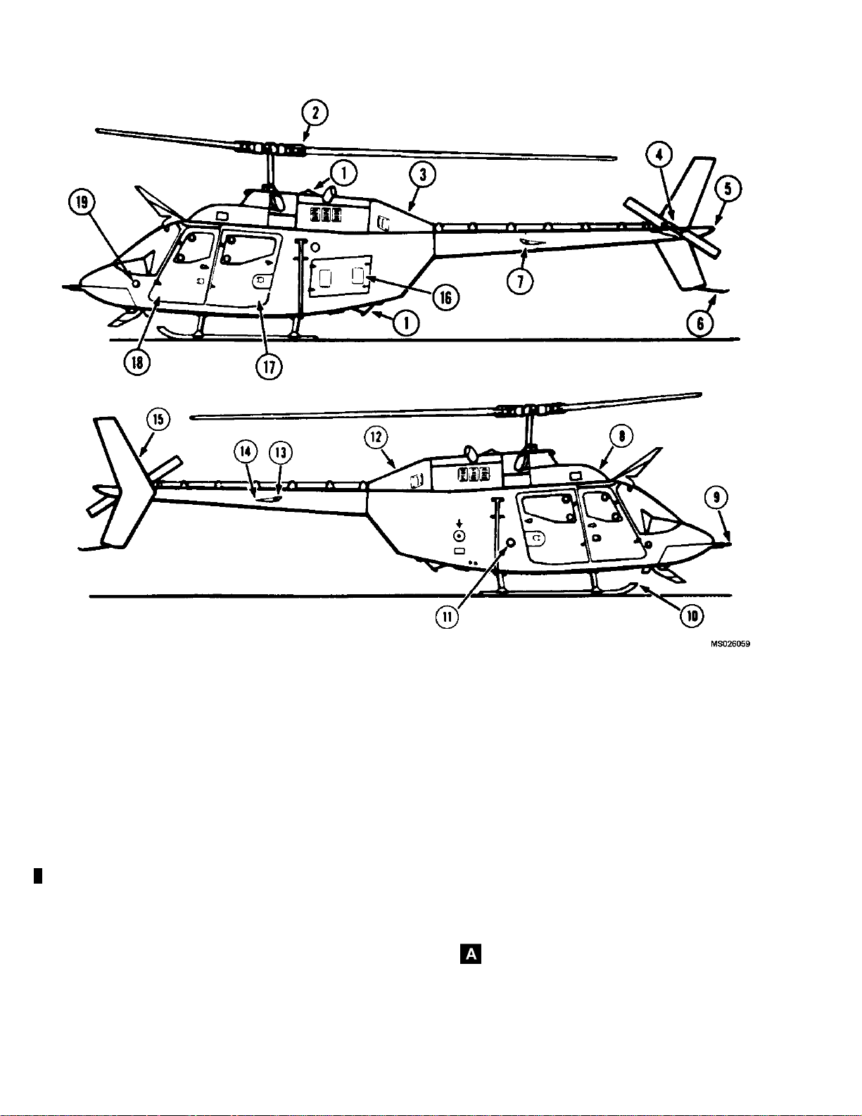
The OH-58A/C helicopter (figure 2-1
C.) is a single engine, observation type helicopter de-
signed for landing and takeoff from prepared or unprepared surfaces. The fuselage consists of the forward
section, intermediate or transition section, and the aft
or tailboom section. The forward section provides the
cabin and fuel cell enclosure as well as pylon support.
Entrance to the cabin is provided by two doors on each
side. The pilot station ( figure 2-3
is located on the right and the copilot/observer station is
located on the left side of the helicopter. The area aft of
the pilot and copilot may be used as a cargo/pass
ger compartment. The intermediate section supports
the engine and includes the equipment and electronic
compartment. The tailboom supports the hor
bilizer, vertical sta bilizer, and tail rotor. The basic structure of the forward section consists of a lower-curved
honeycomb sandwich panel and an upper
aluminum beam. The core of the sandwich structure is
aluminum alloy throughout. The faces are aluminum alloy except in the fuel cell region, w
glass. The aluminum alloy sandwich panel is capable of
withstanding the specified design cargo loadings, while
the fiberglass sandwich suppor
The rotor, transmission, and engine are supported by
the upper longitudinal beam. The upper and lower structures are interconnected by
and a centerpost to form an integrated structure. The
most forward and aft bulkheads act as carry-through
structure for the skid lan
boom is a monocoque structure with aluminum skin and
aluminum substructure.
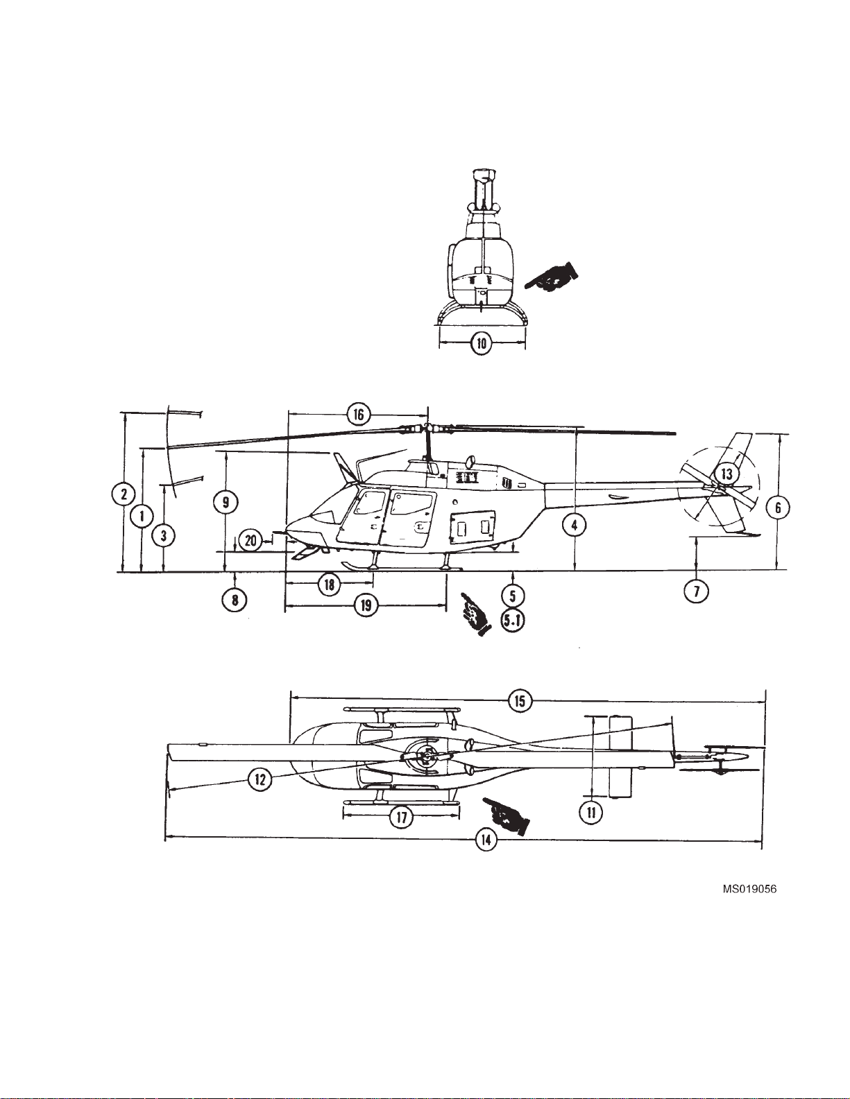
a. Dimensions. Princi
copter areas are shown in figure 2-5.
ts the fuel c ell pressures.
three fuselage bulkheads
ding gear crosstubes. The tail-
pal dimensions of the heli-
A. and figure 2-2
A. and figure 2-4 C.)
en-
izontal sta-
longitudinal
here they are fiber-
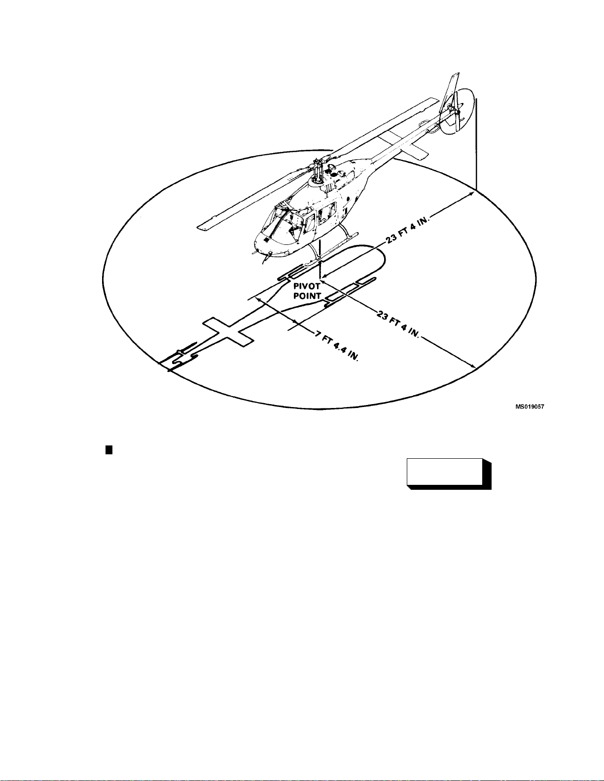
b. Turning Radius and Ground Clearance. (Refer
to figure 2-6.)
c. Weights. The h elicopter weight empty and gross
operating weight will change according to the configuration or equipment installed for the type of mission to
be performed. Refer to Chapter 6, Weight/Balance and
Loading.
d. Crew Configuration. The crew consists of the
pilot alone, pilot and copilot, or pilot and observer.
2-2. PASSIVE DEFENSE.
The armor protection is a combination of ceramic and
fiberglass composite with a small amount of dual hardness steel. The armor protection is removable.
Crew Protection.Armor protection is f urn ished for
the pilot and copilot and consists of panels on seat bottom, seat back, and outboard side of each seat.
2-3. LAND ING GEAR SYSTEM.
a. Standard System. The landing gear system is
a skid type, consisting of two laterally mounted arched
crosstubes, attached to two formed longitudinal skid
tubes. Then landing gear structure members are made
from formed aluminum alloy tubing with steel skid shoes
to minimize skid wear. The gear assembly is attached
with straps/clamps at four points to the fuselage structure, therefore, gear removal for maintenance can easily
be accomplished. The manually retractable and quickly
removable wheel assemblies have been provided to
facilitate helicopter ground han dlin g operations.
b. High Skid Gear. The high skid gear, when installed, will provide an approximate additional 14 inches
of ground clearance. T
accomplished in snow and rough terrain areas.
his will improve landings to be
Change 14 2-1
Page 44
TM 55-1520-228-10
1.
2. Main Rotor Hub and Blades 12.
3.
4. Tail Rotor Hub and Blade 14.
5.
6.
7.
8. Forward Transmission Fairing 18.
9. Pitot Tube 19.
10.
Figure 2-1. General Arrangement (Sheet 1 of 2)
2-2 Change 12
Anti-Collision Light
Engine Oil Tank Drain Access Door
Position Light (White)
Tail Skid
Position Light (Red)
Landing Gear
11.
13.
15. Vertical Fin
16.
17.
Fuel Filler Cap
Aft Engine Cowling
Position Light (Green)
Horizontal Stabilizer
Battery and Avionics Compartment Door
Passenger Door (Left)
Copilot Door
Left Static Port
Page 45
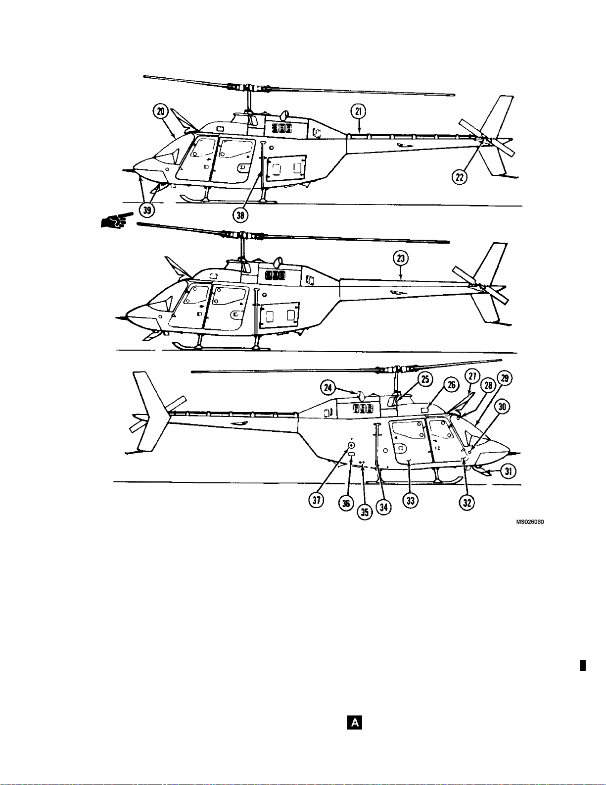
TM 55-1520-228-10
20. Windshield 31.
21.
22.
23.
24. Engine Exhaust 35. Battery Vent
25. Engine Air Inlet 36. External Power Receptacle
26. Forward Transmission Fairing Inspection Door 37.
27.
28.
29.
30.
Tail Rotor Driveshaft
Tail Rotor Gearbox
Tail Rotor Driveshaft and Cover (if installed)
UpperCutterAssembly
Free Air Temperature (FAT) Gage
Windshield Deflector/Cutter Assembly
Right Static Port
F igure 2-1. General Arrangement (Sheet 2 of 2)
32. Pilot Door
33.
34.
38.
39. Landing Light
Lower Cutter Assembly
Passenger Door (Right)
FM Homing Antenna (Right Side)
Ground Receptacle
FM Homing Antenna (Left Side)
Change 10 2-3
Page 46
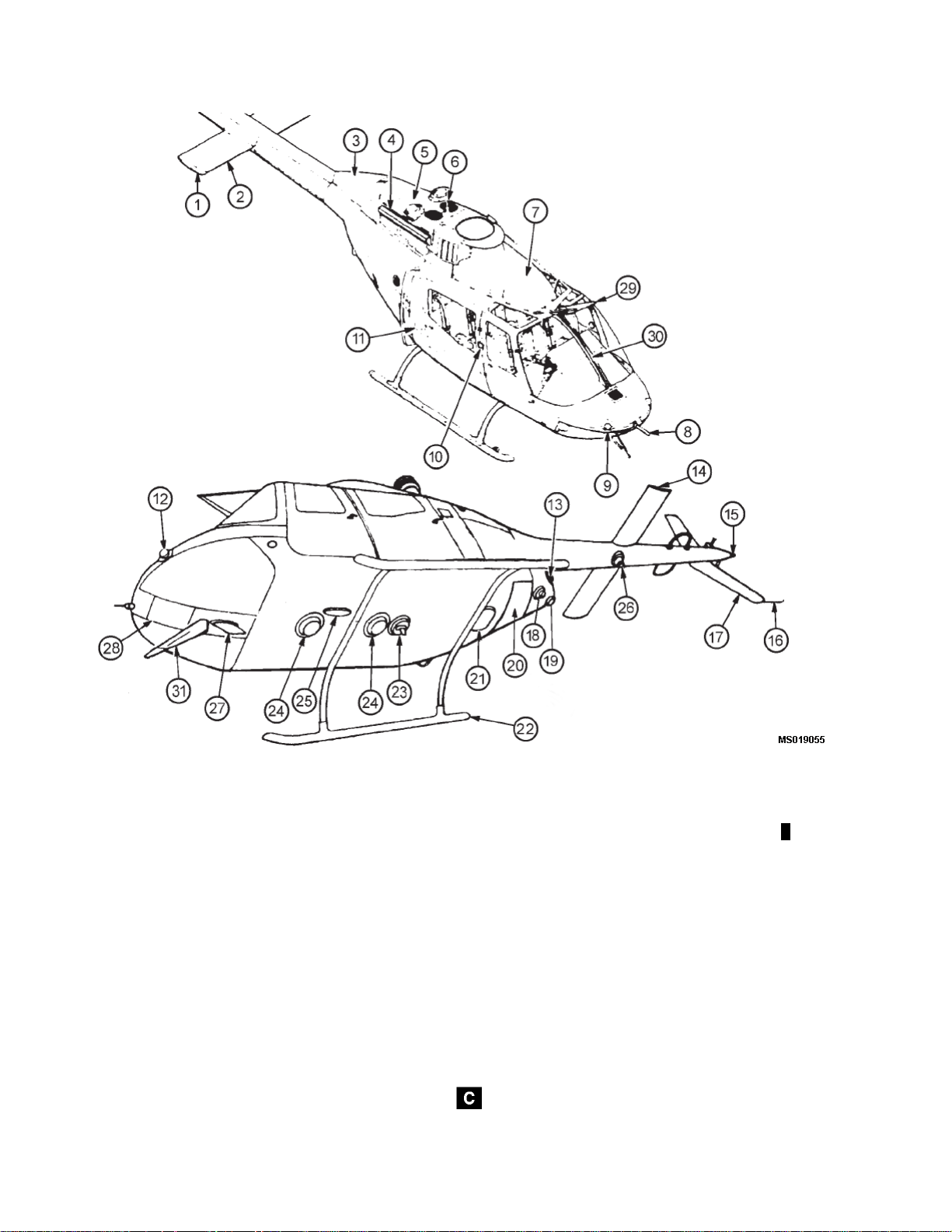
TM 55-1520-228-10
1.
2.
3.
4.
5.
6.
7.
8. Pilot Tube 24. Radar Altimeter Antenna
9. Right Forward Radar Warning Antenna 25. Marker Beacon Antenna
10. Door Lock 26. Transponder Antenna
11.
12.
13.
14.
15.
16.
2-4 Change 14
Position Light (Green)
Horizontal Stabilizer
Aft Engine Cowling
Infrared Suppression Shield
Aft Engine Cowling
Upper Anti-Collision Light
Forward Transmission Fairing 23. Radar Warning Blade Antenna
Fuel Filler Cap
Left Forward Radar Warning Antenna
Left Aft Radar Warning Antenna
Position Light (Red)
Position Light (White)
Tail Skid
Figure 2-2. General Arrangement Typical (Sheet 1 of 2)
17. Vertical Fin
18.
19.
20.
21. ADF Loop Antenna
22.
27. UHF Antenna
28. Landing Light
29.
30.
31.
Lower Anti-Collision Light
Aft Proximity Warning Antenna
ADF Sensor Antenna
Landing Gear
Upper Cutter Assembly
Windshield Deflector/Cutter Assembly
Lower Cutter Assembly
Page 47
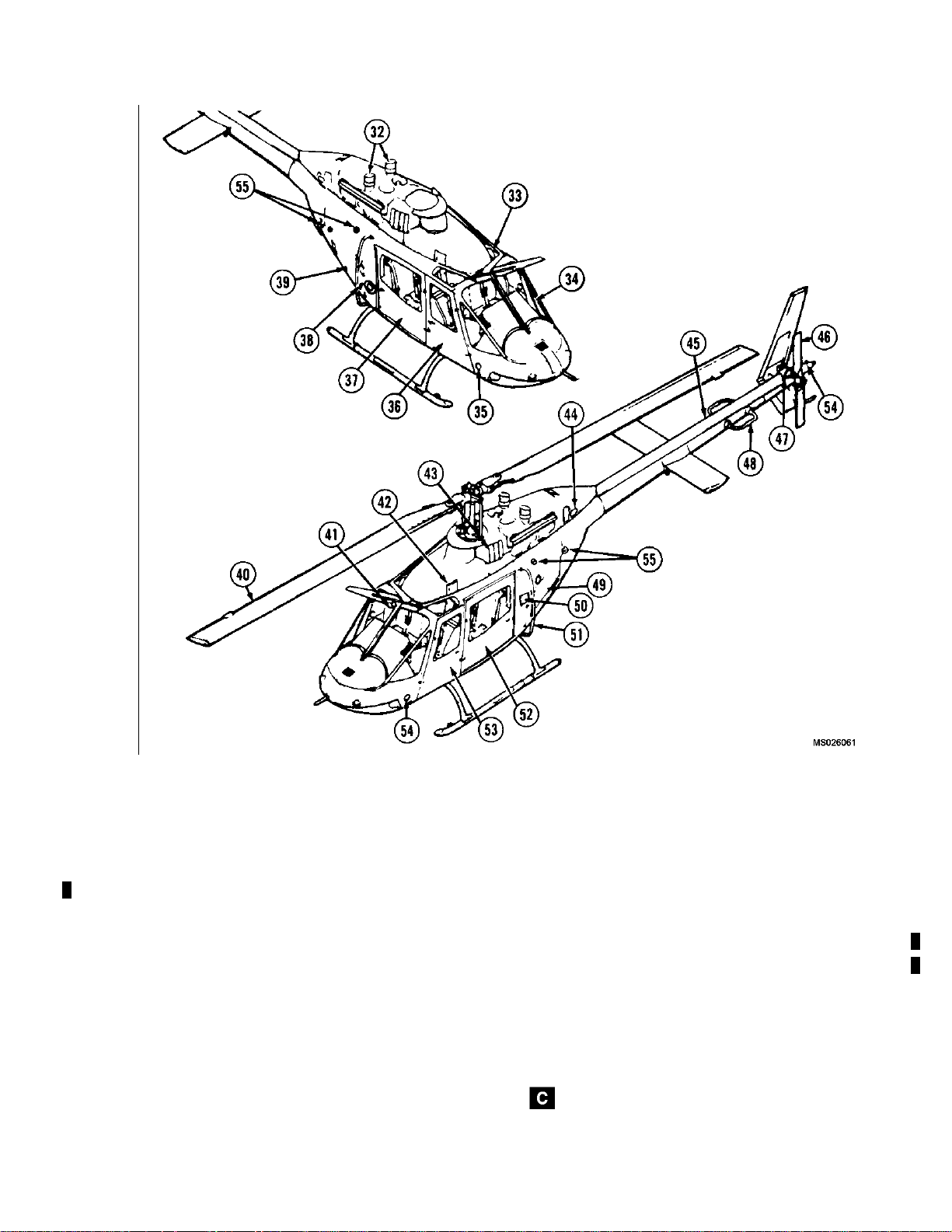
TM 55-1520-228-10
32.
33. FM No. 2 Antenna 46. Tail Rotor Blade and Hub
34.
35.
36. Pilot Door 49.
37. Passenger Door 50.
38. Battery Vent 51. FM Homing Antenna
39. External Power Receptacle 52. Passenger Door
40. Main Rotor Blades and Hub 53.
41.
42. Forward Transmission Fairing Inspection Door
43. Engine Air Inlet 56.
44.
Infrared Engine Exhaust
Windshield (Flat Glass)
Right Static Port
Free Air Temperature (FAT) Gage
Engine Oil Tank Drain Access Door
Figure 2-2. General Arrangement Typical (Sheet 2 of 2)
45.
47.
48.
54.
55.
Tail Rotor Driveshaft Cover
Tail Rotor Gearbox
VOR Antenna
Battery and Avionics Compartment Door
Step
Copilot Door
Left Static Port
NVG Position Lights
Ta il C o ne
Change 12 2-5
Page 48
TM 55-1520-228-10
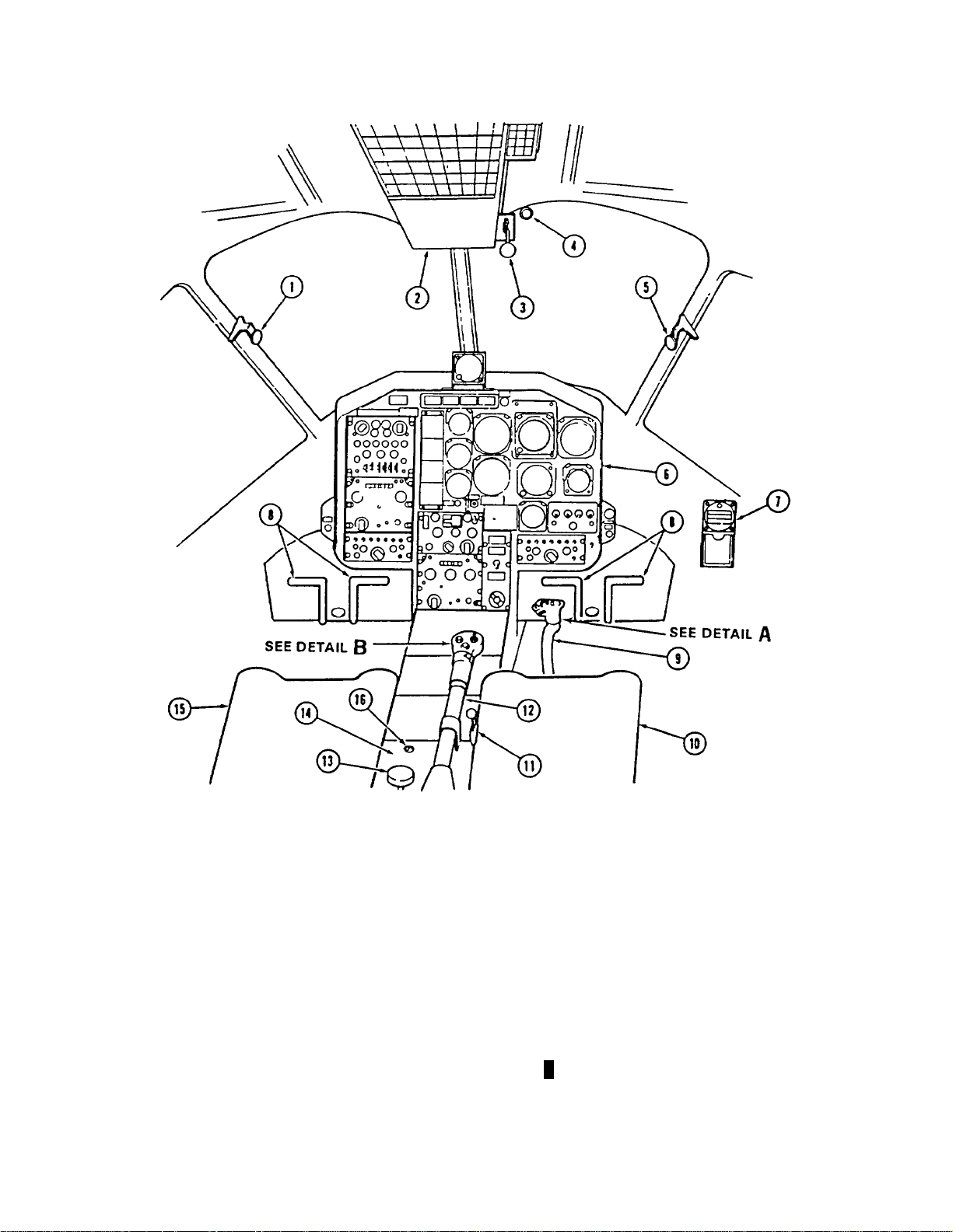
(Figure 2-3 Sheet 1 of 2)
(Figure 2-3 Sheet 2 of 2)
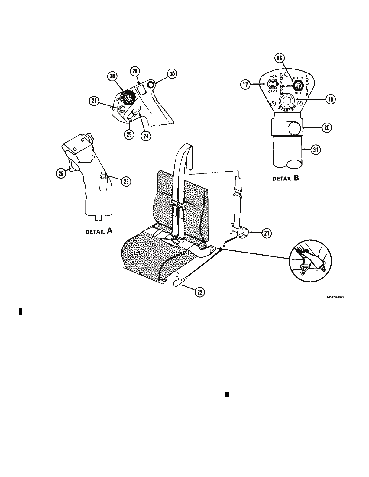
1. Copilot Door Emergency Jettison Handle
2. Overhead Console
3. Fuel Shutoff Valve
4. Free Air Temperature (FAT) Gage
5. Pilot Door Emergency Jettison Handle
6. Instrument Panel
7. Magnetic Compass
8. Anti-Torque Pedals
Figure 2-3. Compartment Diagram
9. Pilot Cyclic Stick
10. Pilot Seat
11. Inertia Reel Control Handle
12. Pilot Collective Stick
13. Collective Friction Control Adjustment
14. Pedestal
15. Copilot Seat
16. Ignition Key Lock Switch
206061-90-1
A (Sheet 1 of 2)
2-6
Page 49
TM 55-1520-228-10
17.
18.
19.
20.
Governor RPM Switch
Search/Landing Lights
Starter Switch
Engine Idle Release Control
25.
Radio Transmit Switch
26. Not Used
27. Not Used
28. Not Used
21. Inertia Reel 29. Not Used
22.
Inertia Reel Control Handle
30.
Force Trim S witch
23. Not Used 31. Throttle
24.
ICS Sw itch
Figure 2-3. Compartment Diagram
32.
Controllable Landing Light Switch
A. (Sheet 2 of 2)
Change 14 2-7
Page 50
TM 55-1520-228-10
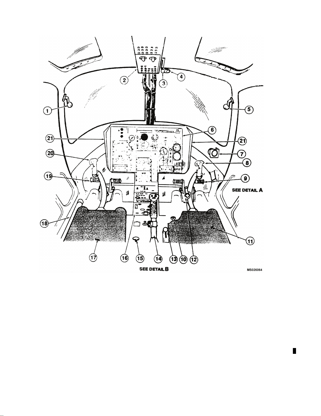
NOTE
Round glass model shown
1. Copilot Door Emergency Jettison Handle 12. Anti-Torque Pedal Adjuster
2. Overhead Console 13. Inertia Reel Control Handle
3. Fuel ShutoffValve 14. Pilot Collective Stick
4. Free Air Temperature (FAT) Gage 15. CollectiveFrictionControlAdjustment
5. Pilot Door Emergency Jettison Handle 16. Console
6. Instrument Panel 17. Copilot Seat
7. Magnetic Compass 18. Copilot Collective Stick
8. Pilot Cyclic Stick 19. Copilot Anti-Torque Ped als
9. Pilot Anti-Torque Pedals 20. Copilot Cyclic Stick
10. Cyclic Friction Control Adjustment 21. Glareshield
11. Pilot Seat
Figure 2-4. Pilot and Copilot/Observer Station Diagram (Sheet 1 of 3)
2-8 Change 14
Page 51
TM 55-1520-228-10
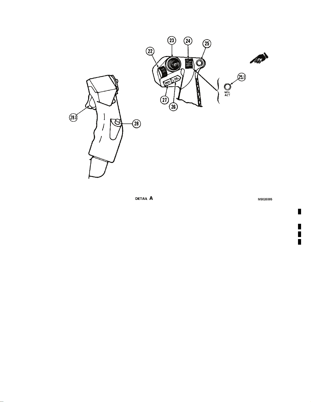
22. Not Used 26.
23. Not Used 27.
ICS Switch
Radio Transmit Switch
24. Not Used 28. Not Used
25.
Force Trim Switch
28.1 Not Used
25.1 Not Used
Figure 2-4. Pilot and Copilot/Observer Station Diagram (Sheet 2 of 3)
Change 10 2-9
Page 52
TM 55-1520-228-10
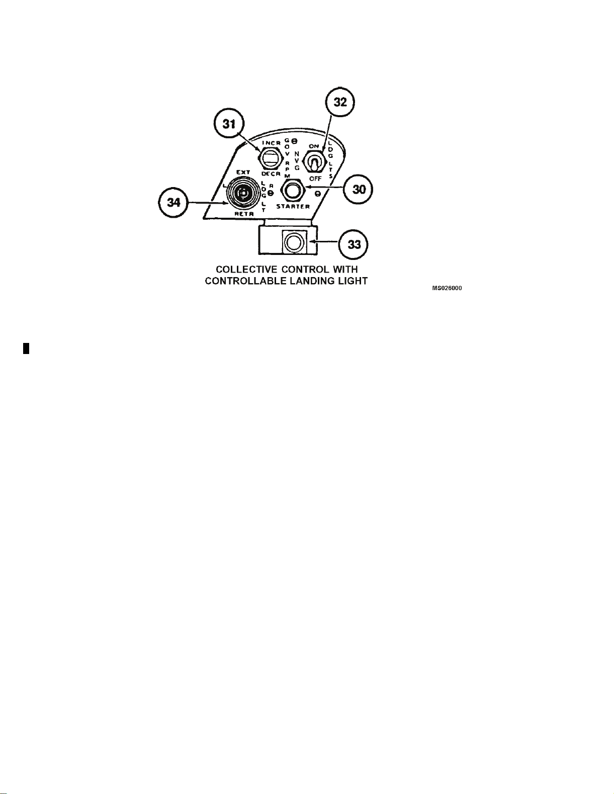
29. Deleted
30.
Starter S witch
31.
Governor RPM Switch
32.
Search/Landing Lights
33.
Engine Idle Release Control
34.
Controllable Landing Light Switch
35. Deleted
Figure 2-4. Pilot and Copilot/Observer Station Diagram (Sheet 3 of 3)
2-10 Change 14
Page 53
TM 55-1520-228-10
Figure 2-5. Principal Dimensions (Sheet 1 of 2)
Change 13 2-11
Page 54

TM 55-1520-228-10
HEIGHT STANDARD
SKID GEAR
1.
Forward Tip of Main Rotor (Static Position to Ground
withDroop) ...................................
2.
Forward Tip of Main Rotor to Ground (Tie-Down) . 12. ft. 0.0 in. 12 ft. 6.0 in. 12 ft. 1.9 in.
3.
Forward Tip of Main Rotor to Ground (Tie-Down) . 6 ft. 8.0 in. 7 ft. 2.0 in. 6 ft. 10.0 in.
4.
Ground to Top of Main Rotor Reservoirs . . . . . . . . . 9 ft. 7.0 in. 10 ft. 9.0 in. 10 ft. 10.0 in.
5.
Bottom ofCabin ...............................
6.
Top of Vertical Stabilizer . . . . . . . . . . . . . . . . . . . . . . . . 8 ft. 1.5 in. 10 ft. 1.5 in. 11 ft. 1.0 in.
7.
Tail Skidto Ground ............................ 1 ft. 4.4 in. 3 ft. 4.4 in. 4 ft. 4.0 in.
8.
LowerCuttertoGround ........................
9.
UpperCuttertoGround ........................ 7 ft. 9.5 in. 9 ft. 9.5 in. 9 ft. 10.5 in.
WIDTH
10.
SkidGear ..................................... 6 ft. 5.4 in. 7 ft. 3.0 in. 11 ft. 6.1 in.
11.
Horizontal Stabilizer . . . . . . . . . . . . . . . . . . . . . . . . . . . 6 ft. 5.2 in. No Change No Change
DIAMETERS
12. MainRotor ....................................
9 ft. 6.0 in. 10 ft. 0.0 in. 9 ft. 7.9 in.
13.0 in. 27.0 in. 28.0 in.
12.0 in.
35 ft. 4.0 in. No Change No Change
HIGH SKID
GEAR
2 ft. 2.0 in. 2 ft. 3.0 in.
FLOAT
GEAR
13. TailRotor .....................................
LENGTH
14.
Overall (Main Rotor Fore and Aft) to Af
Skid ..........................................
15.
Nose of Cabin to Aft End of Tail Skid . . . . . . . . . . . . 32 ft. 2.0 in. No Change No Change
16.
Nose of Cabin to Center Line 8 ft. 1
Rotor .........................................
17.
SkidGear ..................................... 8 ft. 1.3 in. 10ft. 4.2 in. 19 ft. 5.0 in.
18.
Nose of Cabin to Center Line of F
Tube .........................................
19.
Nose of Cabin to Center Line of Aft Forward Cross
Tube .........................................
20. PitotTube ..................................... 6.8 in.
* Check antennas that may protrude lower
Figure 2-5. Principa
t End of Tail
0.1ofMain
orward Cross
l Dimensions (Sheet 2 of 2)
5 ft. 5.0 in. No Change No Change
40 ft. 11.8 in. No Change No Change
8 ft. 10.1 in. No Change No Change
6 ft. 0.0 in. 5 ft. 9.4 in. 5 ft. 11.7 in.
10 ft. 9.0 in. 10 ft. 6.3 in. 10 ft. 8.7 in.
No Change No Change
2-12 Change 12
Page 55
TM 55-1520-228-10
Figure 2-6. Turning Radius and Ground Clearance
c.
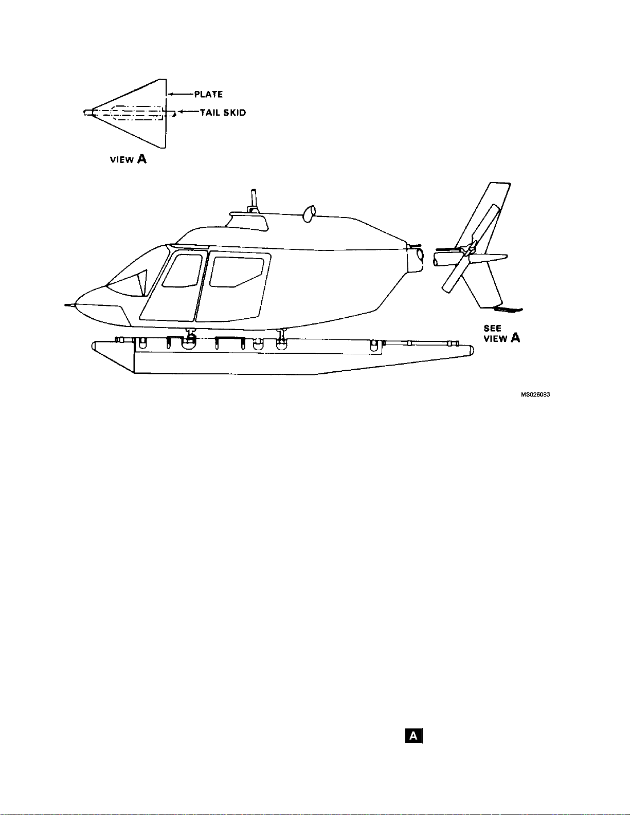
A. Floa
ts of two streamlined multi-ce ll inflatable floats,
consis
float support tubes, crosstubes, and necessary fittings
required to equip the helicopter for water landings. A
gular plate is attached to the tail skid for added con-
trian
trollability and protection of the tail rotor in the event of a
tail low water landing. Landing may be made on smooth
ces that do not have protrusions that could damage
surfa
floats.
d. Tail Skid. A tubular steel tail skid is attached to
wer section of the v ertical fin and provides protec-
the lo
tion for the tail rotor in landings by indicating a tail low
condition.
tGear.The float landing gear (fig ure 2-7)
2-4. COCKPIT AND CABIN DOORS.
WARNING
Inadvertent jettisoning of cockpit doors is possible if jettison handle is utilized as a handhold,
d rest during flight.
or han
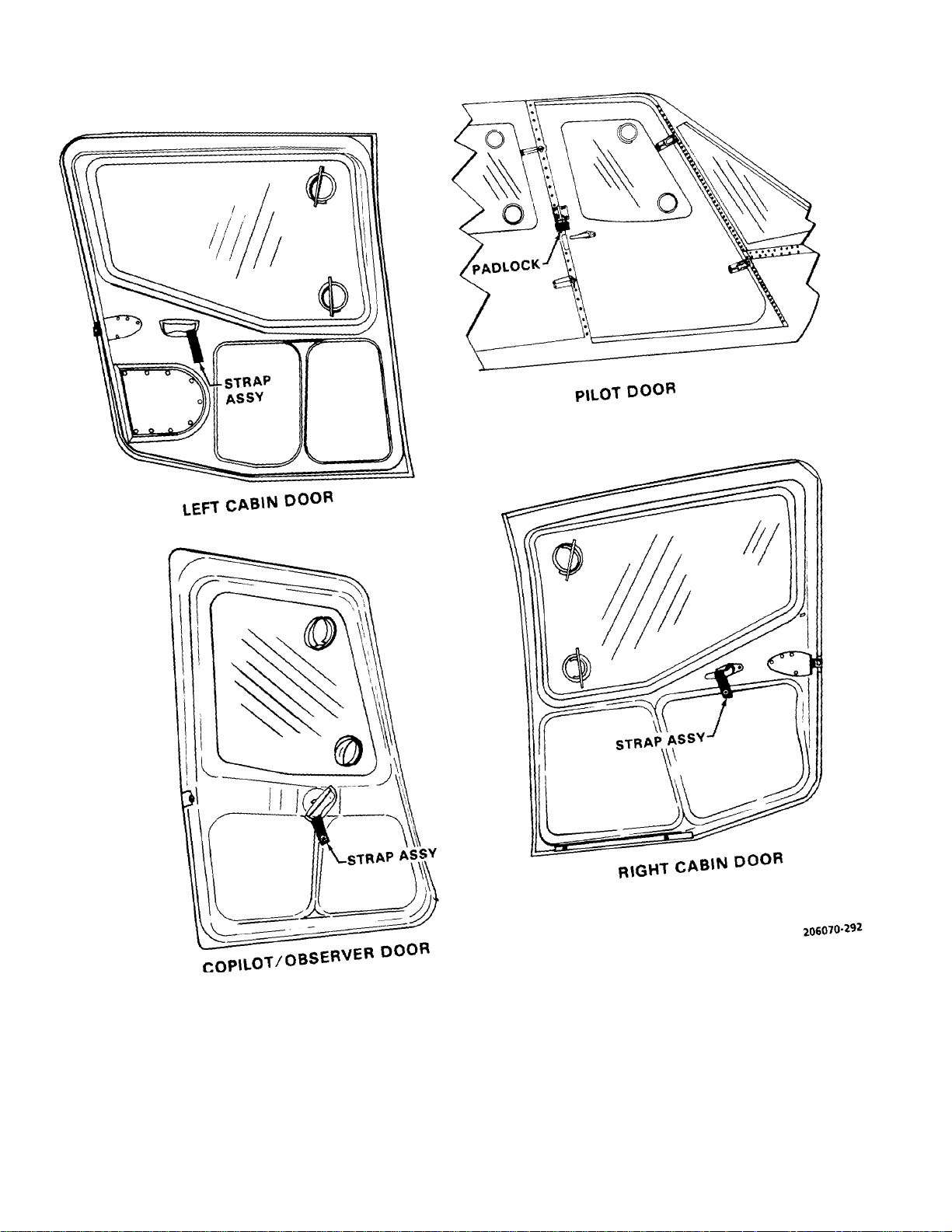
Four entrance doors are provided for ac cess to the aircraft interior. The doors are of bonded sheet metal construction with ac rylic plastic windows. Each door may
be jettisoned by means of emergency jettison handle.
All fou r doors are provided with d oo r lock devic es . The
pilot door has a padlock while the other three doors have
loop locking devices (figure 2-8).
Change 14 2-13
Page 56
TM 55-1520-228-10
2-14
Figure 2-7. Float Gear Equipped Helicopter
Page 57
TM 55-1520-228-10
Figure 2-8. Locking Devices for Doors
2-15
Page 58

TM 55-1520-228-10
2-5. SEATS.
a. Pilot and Copilot/Observer Seats. The pilot
and copilot/ observer seats are constructed of tubing and
stretched nylon material. Each seat is equipped with
provisions for cushions, safety belts, and shoulder
harness. An inertia reel, with a manually operated
control handle, is incorporated on each seat. The inertia
reel is a mechanical restraining device that is designed
to hold the pilot in a normal seated position during any
maneuver which would tend to pitch the pilot forward.
Each reel is connected to a shoulder harness with a web
strap. An automatic locking mechanism, a webbing
roller, and a manual control are incorporated in each unit
(figure 2-3).
b. Passenger Seats. The passenger seats are
constructed of aluminum honeycomb panels and form an
integral part of the airframe. The center panel of the
seat back is removable to gain access to the fuel cell. Seats
are equipped with shoulder harness, safety belts, and
cushions. Seating is provided for two passengers or
without seats, space is provided for cargo (figure 2-3).
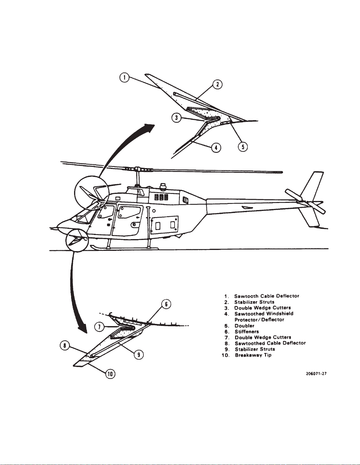
2-6. WIRE STRIKE PROTECTION SYSTEM (WSPS).
WARNING
Flight with the landing light in other than the
fully stowed position on OH58A/C aircraft
may degrade the effectiveness of the Wire
Strike Protection System (WSPS). When use
of the controllable landing light is not
anticipated, it should be in the fully stowed
position.
The WSPS provides protection against frontal impacts
with horizontally strung mechanical and
power transmission wires. The basic system consists of
an upper cutter assembly, a windshield deflector/cutter
assembly, and a lower cutter assembly (figure 2-1 and
figure 2-2). The windshield deflector/cutter assembly,
consisting of a sawtooth equipped aluminum extrusion,
provides deflection mechanism into the upper cutter
while simultaneously abrading thus weakening wire and
provides additional structural support for the upper cutter
mounting. The mechanical cutter assembly (upper and
lower) (figure 2-9) consists of a sawtooth equipped
deflector section, providing deflection/abrading feature
similar to the windshield deflector section, leading into
the primary wire cutting mechanism - wedge type cutting
blades positioned to provide the necessary mechanical
advantage to cut the design objective wires while
minimizing load input into the airframe. The lower cutter
assembly features a "Breakaway Tip" designed to shear
when relatively large ground contact forces are
experienced and before helicopter structural damage is
incurred. However, the tip shear rivets are designed to
withstand the smaller forces experienced during wire
strikes and the tip will still effectively deflect wires into the
cutter blades.
a. Wire Strikes. If avoidance is not possible or not
effective a wire strike will occur. The protection provided
by the WSPS is 90% of frontal area. The cable
impact/ deflection/ cutting sequence of the design
objective cables does not have a significant effect on
aircraft performance, control, crew functioning or blade
flapping.
b. Avoidance. The most effective defense against
wire strikes is avoidance. Because of the many different
encounters that can occur, it is not possible to provide a
procedure to cover every situation. The success in
coping with emergency depends on quick analysis of the
condition and selection of the proper evasive maneuvers
2-16
Page 59
TM 55-1520-228-10
Figure 2-9. WSPS Configuration
2-17
Page 60

TM 55-1520-228-10
SECTION II. EMERGENCY EQUIPMENT
2-7. FIRST AID KIT.
An aeronautical type first aid kit is located on the right
side of the center support column.
SECTION III. ENGINES AND RELATED SYSTEMS
2-9. ENGINE.
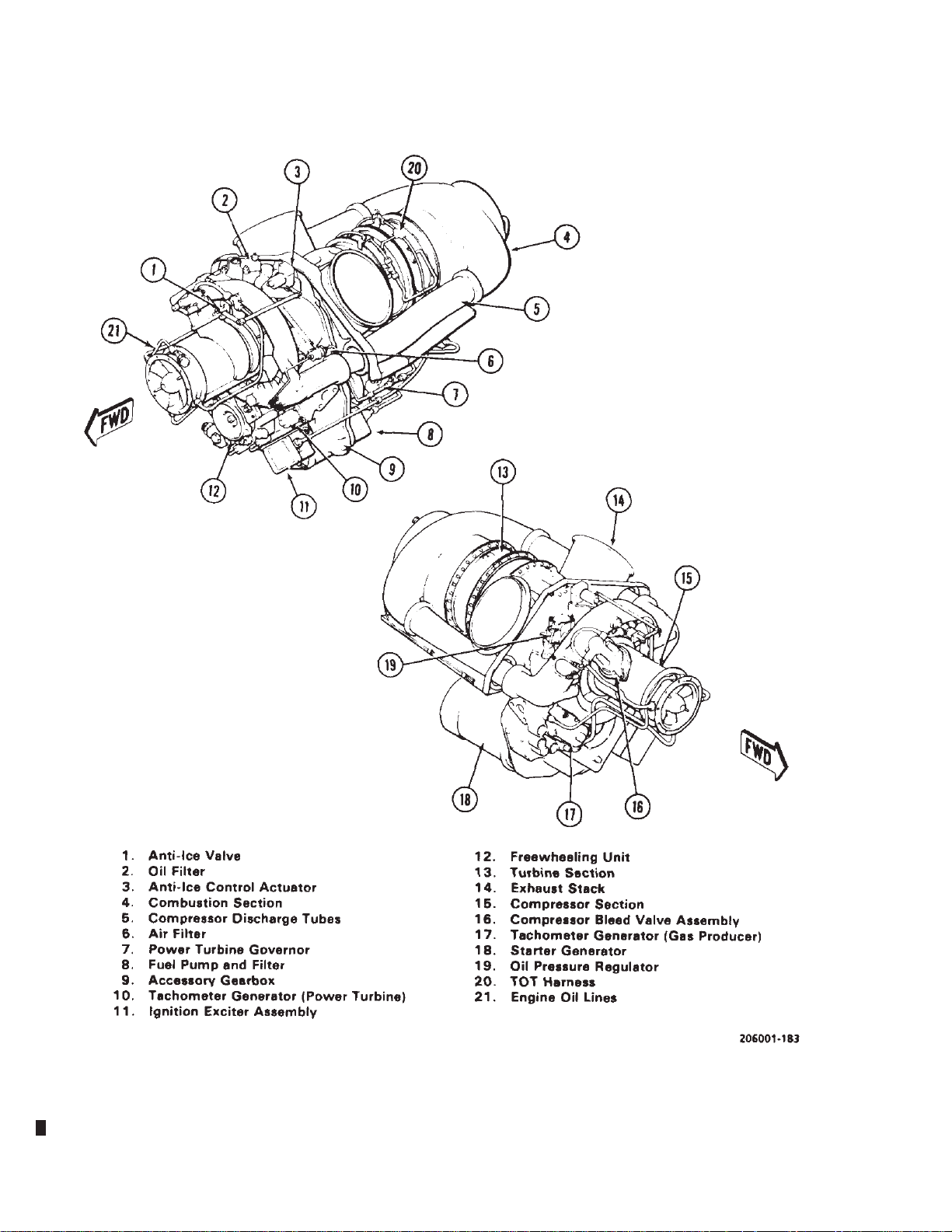
The OH-58A/C helicopter is equipped with a T63-A-720
turbine engine (figure 2-1 1). The engine is designed for
low fuel consumption, light weight, minimum size, maximum reliability and ease of maintenance. The engine is
installed aft of the mast and the passenger compartment. The engine cowl aft of the engine air inlet is removable as a single unit or the hinged section the length
of the engine on either side may be opened individually .
The aft fairing covers the engine oil cooler, provides tail
rotor driveshaft access and provides air intake for the
engine oil cooler. The major engine components are as
follows:
2-8. FIRE EXTINGUISHER.
A portable fire extinguisher is mounted in a bracket located on the right side of the center support column
(figure 9-1).
liner. A spark igniter and fuel nozzle are mounted in the
aft end of the outer combustion case.
c. Turbine. The turbine consists of a gas producer
turbine support, a power turbine support, a turbine and
exhaust collector support, a gas producer turbine rotor,
and power turbine rotor. The turbine is mounted between the combustion section and the power and accessory gearbox. The two-stage gas producer turbine
drives the compressor and accessory gear train. Gas
discharged from the gas producer turbine drives the
two-stage power turbine which furnishes the output
power of the engine. The gas from the power turbine
discharges in an upward direction through twin ducts in
the turbine and exhaust collector support.
a. Compressor. Air enters the engine through the
particle separator to the compressor inlet and is compressed by six axial compressor stages and one centrifugal stage. The particle separator removes dirt and
other contaminates from the incoming air and ejects the
dirt out ducts on either side of the fairing. This allows
cleaned air to enter the engine compressor section. The
compressed air is discharged through the scroll type
diffuser into two external ducts which convey the air to
the combustion section.
b. Combustion Section. The combustion section
consists of the outer combustion case and combustion
d. Power and Accessories Gearbox. The main
power and accessory drive gear train are enclosed in a
single gear case. The gear case serves as a structural
support of the engine. All engine components including
engine mounted accessories are attached to the case.
A two-stage helical and spur gear set is used to reduce
rotational speed from the power turbine to the output
drive spline. Accessories driven by the power turbine
gear train (N2) are the power turbine (N2) tachometergenerator, power turbine governor, and torquemeter.
The gas producer (N1) drives the compressor, and
through an associated gear train drives the fuel pump,
gas producer (N1) tachometer-generator, gas producer
fuel control, starter-generator, and engine oil pump.
2-18 Change 11
Page 61

TM 55-1520-228-10
FIGURE 2-10. HAS BEEN DELETED.
Change 11 2-19
Page 62
TM 55-1520-228-10
2-20 Change 11
Figure 2-11. Engine
Page 63

TM 55-1520-228-10
2-10. ENGINE COMPARTMENT COOLING.
Openings are provided on both sides of the engine and
top cowling for compartment cooling. The center cowl
section houses the engine air inlet, the inlet bellmouth
and the forward firewall. Suspended below the engine is
a stainless fire shield. Below the fire shield is a titanium
floor which acts as a drip pan and also gives insulation
from heat.
2-11. INDUCTION SYSTEM.
The engine air inlet system consists of an induction
fairing with inlets on each outboard side. This fairing
provides mounting for the particle separator. The
particle separator removes dirt and other contaminates
from the incoming air and ejects the dirt out eductor
tubes on either side of the fairing. This allows cleaned
air to enter the engine compressor section. Removable
reverse flow inlet fairings may be installed over the air
inlets on modified induction fairings. These reverse flow
fairings minimize ram effect of falling or blowing snow,
thus permitting effective operation of the particle
separator and preventing engine flame-out caused by
ingestion of snow.
a. Intake Ducting. The engine air intake ducting
consists of louvered openings and a large circular air
inlet opening. The louvered openings are located on left
and right cowl panels.
b. Particle Separator. Foreign matter is removed
from the engine inlet air by a centrifugal-type particle
separator. The particle separator consists of a group of
separator tube assemblies arranged in rows and
positioned in a front and rear sheetmetal panel and a
scavenge system. The separator tube assemblies
consist of an inlet tube, a swirl tube which is bonded
inside the inlet tube, and an outlet tube. The scavenge
system consists of a bleed air manifold, bleed air
nozzles, and ejector tubes which are contained in two
ejector boxes located beneath the separator tube
assemblies. The bleed air manifold is attached to the
ejector boxes and is connected directly to the engine
compressor scroll with bleed air inlet fittings. Air enters
the inlet tube and is spun by the swirl tube. Clean air
then enters the engine inlet plenum chamber through the
outlet tube while foreign material is centrifuged into the
scavenge system. The foreign material is ejected
overboard by the vacuum-cleaner effect created by
engine bleed air as it is discharged through venturies in
the eductor tubes. Reverse flow inlet fairings may be
attached to the engine air inlets. These sheet metal
fairings make it impossible for air to enter the plenum
chamber without first making two 180° turns. These
abrupt changes in airflow greatly reduce the probability
of engine flame-out associated with snow ingestion.
2-12. ENGINE INLET ANTI-ICING SYSTEM.
The compressor inlet guide vanes and front bearing
support hub are the only engine components with anticing provisions. Anti-icing is provided by the use of
compressor bleed air. Anti-icing is actuated by placing
ENG DEICE switch on overhead console (figure 2-12) to
ENG DEICE position.
2-13. ENGINE FUEL CONTROL SYSTEM.
The system controls engine power output by controlling
the gas producer speed. Gas producer speed levels are
established by the action of the power turbine fuel
governor which senses power turbine speed. The power
turbine (load) speed is selected by the operator and the
power required to maintain this speed is automatically
maintained by power turbine governor action on metered
fuel flow. The power turbine governor lever schedules
the power turbine governor requirements. The power
turbine governor schedules the gas producer speed to a
changed power output to maintain output shaft speed.
a. Deleted.
b. Throttle. Rotating the throttle (figure 2-4) to the
full open position allows the power turbine governor to
maintain a constant rpm. Rotating the throttle toward the
dosed position will cause the rpm to be manually
selected instead of automatically selected by the power
turbine governor. Rotating the throttle past the engineidle stop to the fully dosed position shuts off fuel flow. A
manually operated idle stop is incorporated to prevent
inadvertent throttle closure. The idle stop is controlled
by the engine idle release control (figure 2-4).
Change 10 2-21
Page 64
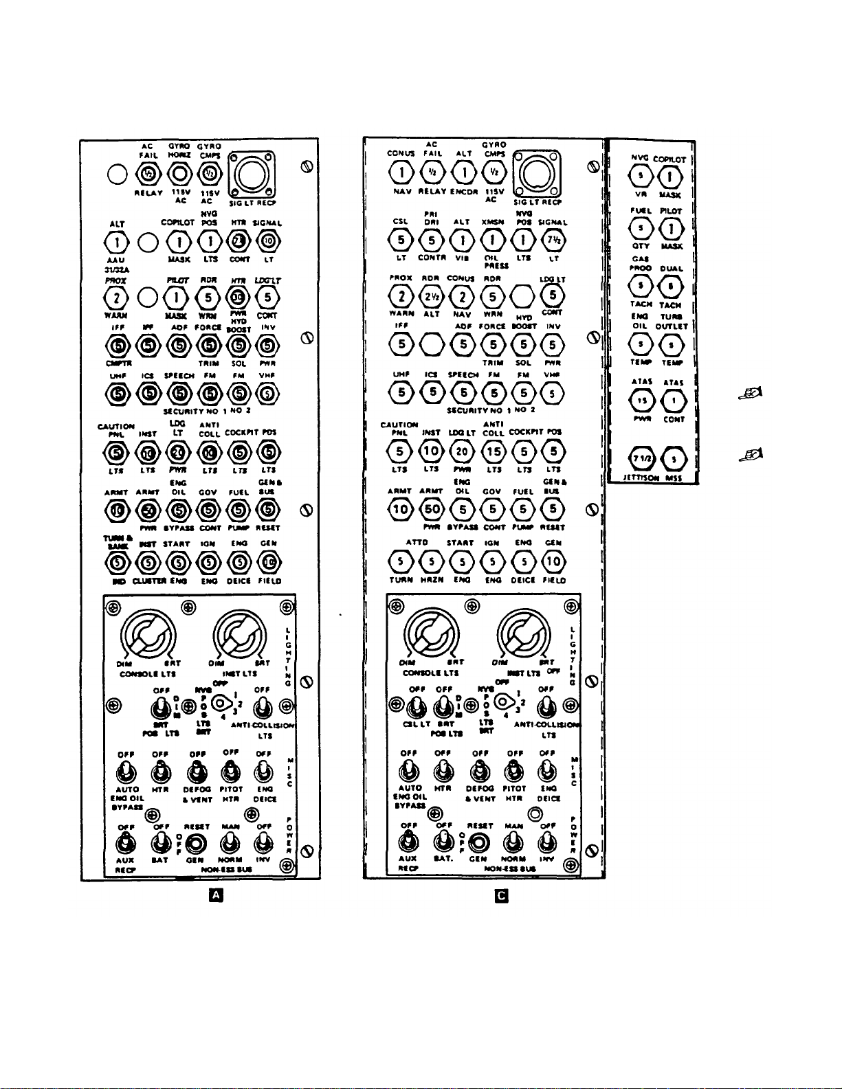
TM 55-1520-228-10
2-22 Change 10
Figure 2-12. Overhead Console
Page 65
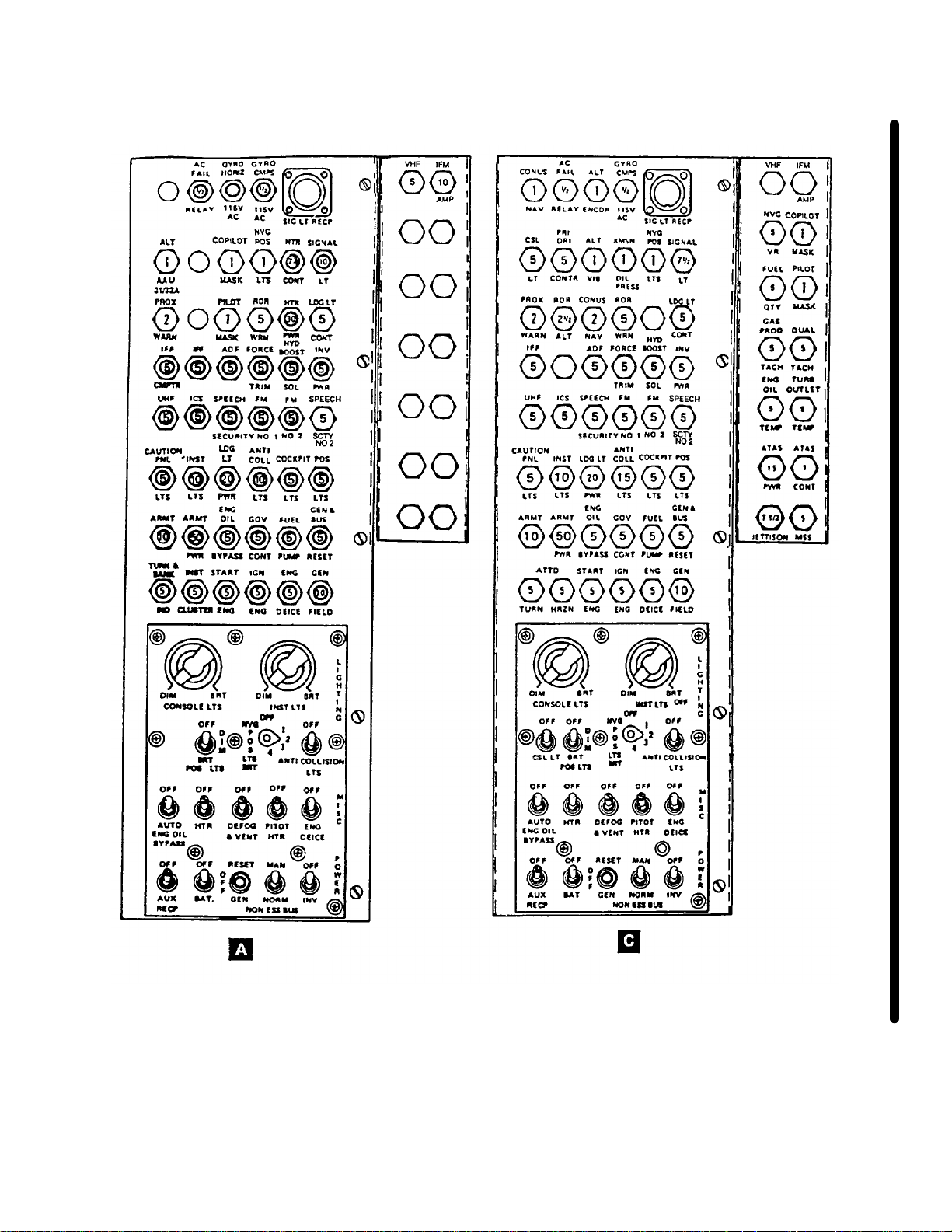
TM 55-1520-228-10
Figure 2-12.1. Overhead Console with AN/ARC-201 (Typical)
Change 10 2-22.1/(2-22.2 blank)
Page 66

Page 67

TM 55-1520-228-10
c. Droop Compensator. A droop compensator
maintains engine rpm (N2) as power demand is increased. The compensator is a direct mechanical
linkage between the collective stick and the speed
selector lever on the N2 governor. Droop is defined
as the speed change in N2 rpm as power is increased
from a no-load condition. Without droop compensation,
instability would develop as eng in e output is increased,
resulting in N1 speed overshooting or hunting the value
necessary to satisfy the new power condition. If N2
power is allowed to droop, other than momentarily, the
reduction in rotor speed could become critical.
d. Engine Idle Release Control. The engine idle
release is a spring loaded plunger mounted on the
switch box of the pilot collective stick (figure 2-3 and
figure 2-4). The plunger prevents the pilot from accidentally retarding the throttle beyond engine idle position.
This acts as a safety feature by preventing inadvertent
engine shutdown. The plunger need not be depressed
when performing an engine start or runup; however,
the plunger must be depressed when accomplishing
an engine shutdown or when it is desired to retard the
power c ontrol below the engine idle position.
e. Governor RPM Switch. The GOV INCR/DECR
switch is mounted on the pilot collective stick (figure 2-3
and 2-4). The switch is a three-position momentary type
and is held in the INCR position (FWD) to increase the
power turbine (N2) speed or DECR position (AFT) to decrease the power turbine (N2) speed. Regulated power
turbine speed may be adjusted in flight through the operating range by movement of the switch as required.
f. Gas Producer Fuel Control. The gas producer
fuel control has a bypass valve, metering valve, acceleration bellows, governing and enr
ichment bellows,
manually operated c ut off v alve, maximum pressure
relief valve, and a torque tube seal and lever assembly.
A maximum pressu re relief valve is incorporated to
protect the system from excessive fuel pressure.
g. Power Turbine Governor. The power turbine
speed is scheduled by the power turbine governor
lever and the power turbine speed scheduling cam.
The cam sets a governor spring load which opposes
a speed-weight output. Overspeed protection of the
power turbine governor becomes effective at approximately 108% N2. This governing action will result in a
pulsating increase/decrease of engine power.
h. Deleted.
i. Fuel Pump and F ilter Assembly. The fuel pump
and filter assembly incorporates a single gear-type
pumping element, a low pressure barrier filter, a filter
bypass valve, and a bypass pressure regulating valve.
Fuel enters the engine fuel system at the inlet port of the
pump and passes through the low pressure filter b
entering the gear element. The filter bypass valve
allows fuel to bypass the filter element if it becomes
clogged. The bypass return flow from the fuel c
passed back to the inlet of the gear element through a
pressure regulating valve which maintains the bypass
flow pressure above inlet pressure.
j. Deleted.
k. Fuel Nozzle. The fuel nozzle is a sing
dual orifice type unit which contains an integral valve
for dividing primary and secondary fl ow.
l. Deleted.
efore
ontrol is
le-entry
Change 14 2-23
Page 68

TM 55-1520-228-10
2-14. INFRARED SUPPRESSION SYSTEM.
The infrared suppression system is specially formulated
to reduce detection of IR-seeking missiles. The system
consists of two exhaust stacks located at the top of the
engine cowling and two shields located on the side engine cowling (figure 2-2). The exhaust stacks have cooling fins and a shelf around them to reduce the infrared
signature of the hot engine exhaust. The shields on the
side engine cowling prevent detection of the hot engine
area from the sides.
2-15. TEMPERATURE MEASUREMENT
SYSTEM.
The temperature measurement system consists of four
chromel-alumel single junction thermocouples in the
gas producer turbine outlet and an associated integral
harness. The voltages of the four thermocouples are
electrically averaged in the assembly and delivered by
the assembly lead to the airframe terminal block for
reference to the engine temperature indicating system.
2-16. COMPRESSOR BLEED AIR SYSTEM.
The 5th stage compressor bleed valve permits rapid
engine response. The system consists of a compressor
discharge pressure sensing port on the scroll, tubing
from the sensing port to the bleed valve, a compressor
bleed control valve, and a bleed air manifold on the
compressor case. Elongated slots between every other
vane in the compressor 5th stage bleeds compressor air
into a manifold which is an integral part of the compressor case. The manifold forms the mounting flange for the
compressor bleed control valve when the compressor
case halves are assembled. Compressor discharge air
pressure sensing for bleed control valve operation is
obtained at a sensing port of the compressor scroll. The
bleed control valve is normally open. It is closed by
compressor discharge pressure.
unit. Probe type magnetic chip detectors are installed at
the bottom of the power accessory gearbox and the
engine oil outlet connection. All engine oil system lines
and connections are internal with the exception of pressure and scavenge lines to the front compressor support, the gas producer turbine support, and the power
turbine support. The oil cooler blower is an integral part
of the tail rotor drive and is located aft of the freewheeling unit and adjacent to the oil tank.
2-17.1. ENGINE OIL SUPPLY SYSTEM EXTERNAL SCAVENGE OIL FILTER
Compliance with MWO 55-1520-228-50-44).
The in-line external scavenge oil filter is located above
the tail rotor drive shaft, behind the engine oil tank. The
filter assembly consists of a filter element, oil bypass
indicator, and bypass valve. When the filter element
becomes clogged, it will give a warning by extending the
oil bypass (red) indicator. The indicator extends when a
set differential pressure across the filter is exceeded.
When in the reset position, the indicator will be hidden
from view. If the indicator is extended, it can be reset by
pressing in. An extended indicator is no sufficient reason
to ground the helicopter. If filter bypass indicator (red
button) is showing, reset indicator, ground run engine,
and reinspect. If indicator red button is not showing after
ground run, aircraft may be released for operation. If
indicator red button is showing, do not fly aircraft, notify
maintenance.
(After
2-18. IGNITION SYSTEM.
a. The engine ignition system consists of a keylock
ignition switch, a low tension capacitor discharge ignition exciter, a spark igniter lead, and a shunted surface
gap spark igniter. The system derives its input power
from the helicopter 28-volt DC electrical system.
b. The keylock ignition switch (figure 2-13 and figure 2-14) locks out the starter system and prevents unauthorized use of the helicopter, thereby preventing
possible injury to personnel and/or damage to the equipment.
2-17. ENGINE OIL SUPPLY SYSTEM.
The lubricating system is a dry sump type with an external reservoir and heat exchanger. A gear type pressure
and scavenge pump assembly is mounted within the
power and accessory gearbox. The oil filter, filter bypass
valve, and pressure regulating valve are in a unit which
is located in the upper right side of the power and accessory gearbox housing and are accessible from the top
of the engine. The oil tank is mounted aft of the engine
rear firewall on top of the intermediate cabin section. A
check valve is located between the housing and the filter
2-24 Change 11
2-19. STARTERS SWITCH.
The starter switch (figure 2-3 and figure 2-4), located in
the collective stick switch box, is a push button type
switch. When the switch is pressed, the circuit to the
starter relay actuating coil, the igniter unit, and the fuel
boost pump are energized. The switch is released when
the engine start cycle is completed or abort start procedures is completed. The keylock ignition switch must be
ON to complete the ignition circuit. The circuit is protected by the ST ART ENG, IGN ENG and FUEL PUMP
circuit breakers.
Page 69
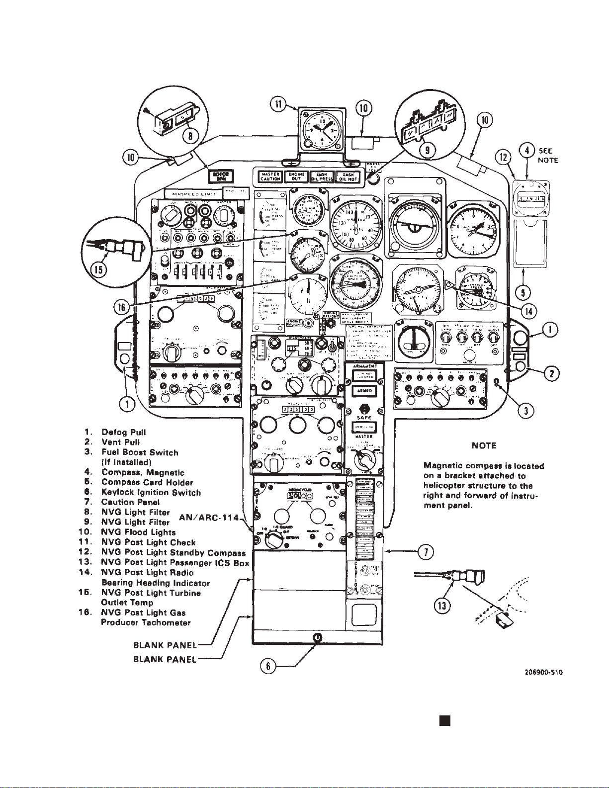
TM 55-1520-228-10
Figure 2-13. Instrument Panel and Console (Typical) A
2-25
Page 70
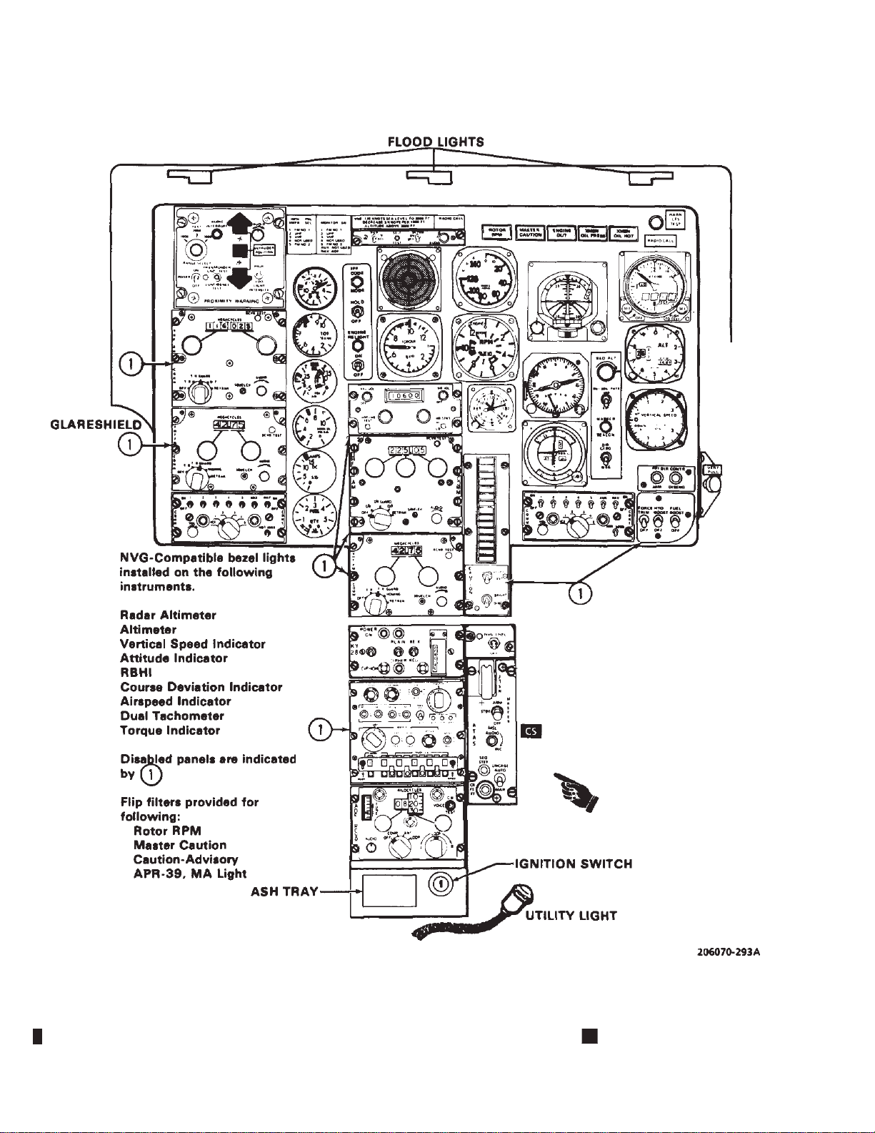
TM 55-1520-228-10
2-26 Change 11
Figure 2-14. Instrument Panel and Console (Typical) C
Page 71
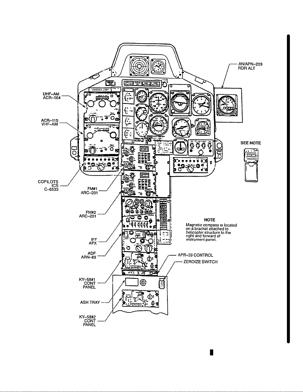
TM 55-1520-228-10
Figure 2-14.1. Instrument Panel and Console with AN/ARC-201 A (Typical)
Change 10 2-26.1
Page 72
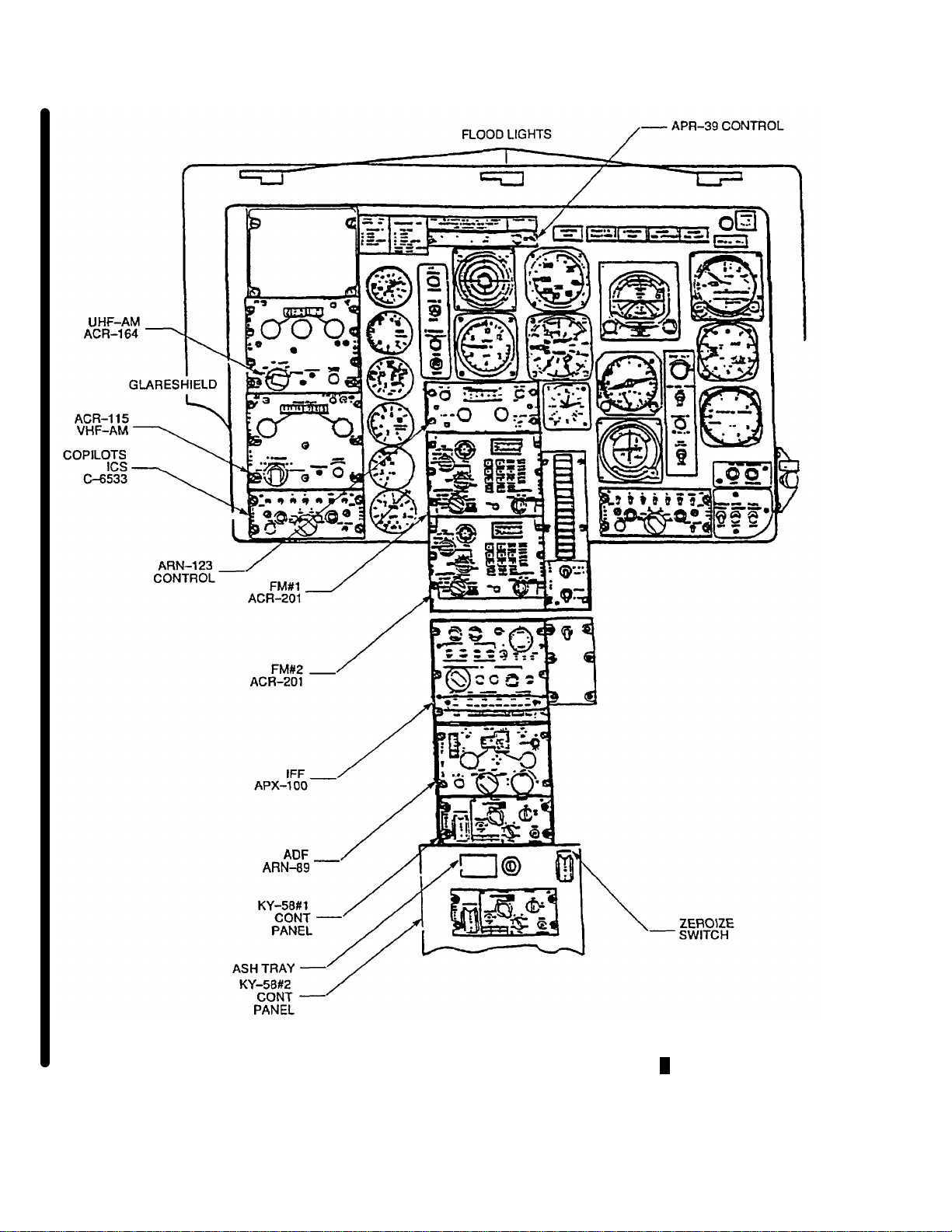
TM 55-1520-228-10
NVG-Compatible bezel lights
installed on the following
instruments.
Radar Altimeter
Altimeter
Vertical Speed Indicator
Altitude Indicator
RBHI
Course Deviation Indicator
Airspeed Indicator
Dual Tachometer
Torque Indicator
Flip filter provided for
following:
Rotor RPM
Master Caution
Caution-Advisory
APR-39, MA Light
Figure 2-14.2. Instrument Panel and Console with AN/ARC-201 C (Typical)
2-26.2 Change 10
Page 73

2-20. ENGINE AUTOMATIC RELIGHT SYSTEM (NOT USED).
An ENGINE RELIGHT ON/OFF switch and an ENGINE
RELIGHT light may be found on the instrument panel.
The automatic relight system has been deactivated and
is not functional. There is no approved functional system
for the OH-58A/C helicopter.
2-21. ENGINE INSTRUMENTS AND INDICATORS.
The engine instruments and indicators are mounted in
the instrument panel or the caution panel in the lower
console. They are described in the following paragraphs
and shown in figure 2-13 and figure 2-14.
TM 55-1520-228-10
C Turbine Outlet T emperature Indicator . The
e.
turbine outlet temperature (TOT) indicator (figure 2-14),
located in the instrument panel, displays temperature in
degrees Celsius of the exhaust gases in the N1 turbine
outlet area. The indicator is powered by 28 Vdc and
protected by TURB OUTLET TEMP circuit breaker.
f. Gas Producer Tachometer. The gas producer
tachometer generator, located on the engine, generates
an AC voltage with a frequency that is a function of gas
producer turbine rotor N1 RPM. The output of the
tachometer generator is delivered to the gas producer
tachometer indicator which indicates the frequency in
terms of percent RPM of gas producer turbine speed.
The power for the gas producer tachometer is engine
generated
A . The helicopter electrical system powers
the C model and is protected by a gas producer tach
circuit breaker.
a. Engine Out Warning. An RPM sensor is connected to the gas producer tachometer. Power is supplied from the CAUTION PNL LTS circuit breaker and
connections are made to the ENGINE OUT warning
light (figure 2-13 and figure 2-14), and to a tone generator which produces a tone in the pilot headset. The warning system is activated when N1 is below 55 $ 3% and
is deactivated above that N1 speed. The audio signal is
the same as the low rotor audio signal.
b. Engine Out Audio Warning. A switch connected to the collective lever disables the engine out
audio warning when the collective lever is in the full
down position.
c. Torquemeter. The torquemeter (figure 2-13 and
figure 2-14), located in the instrument panel, displays
percent of torque produced by the engine. The torquemeter is a direct reading, wetline indicator.
d.
A Turbine Outlet Temperature Gage. A ther-
mocouple harness assembly with four integral probes is
used to sense the temperature of the gases on the outlet
side of the gas producer turbine rotor. A DC voltage
which is directly proportional to the gas temperature it
senses, is generated by each thermocouple. The thermocouple and thermocouple harness provide an average of the four voltages representative of the turbine
outlet temperature (TOT) and this is the temperature
indication on the TOT gage on the instrument panel.
g. Dual Tachometer. The dual tachometer (figure
2-13 A , figure 2-14 C ) located in the instrument panel
displays percent RPM of the engine and rotor. The outer
scale is marked Engine and the inner scale is marked
Rotor. The OH-58A indicators are direct reading instruments which are not dependent on the electrical system.
The OH-58C tach indicators are 28v DC-powered and
protected by the DUAL TACH and GAS PROD TACH
circuit breakers.
h. A Oil Pressure Gage. The oil pressure indicator, located on the instrument panel, is a direct-reading,
wet-line system. Pressure from the pressure side of the
oil pump is indicated in psi. Refer to figure 2-13.
A Oil Temperature Gage. The engine oil tem-
i.
perature gage, located on the instrument panel, is connected to an electrical resistance type thermocouple
and indicates the temperature of the oil at the oil tank
outlet.
C Oil Pressure/Temperature Indicator. The
j.
engine oil pressure/temperature indicator (figure 2-14),
located in the instrument panel, displays engine oil pressure in psi and temperature in degrees Celsius. The
temperature circuit is powered by 28 Vdc and protected
by ENG OIL TEMP circuit breaker. The oil pressure
portion of the indicator is a direct reading wetline system.
Change 10 2-27
Page 74

TM 55-1520-228-10
WARNING
Illumination of the engine oil bypass light may
indicate a severe leak is present or developing,
which could result in total loss of engine oil in a
short period of time.
k. Engine Oil Bypass Caution Light. The ENG
OIL BYPASS caution light (figure 2-13 and figure 2-14),
located on the caution panel, will illuminate when the oil
tank level is approximately 3 pints low. With the ENG
OIL BYPASS switch (figure 2-12) in the AUTO position
the engine oil will bypass the oil cooler. A significant
in engine oil temperature will occur and engine failure
can occur in a few minutes due to excessive engine oil
temperature and/or engine oil loss. The switch in AUT
rise
SECTION IV. FUEL SYSTEM
2-22. FUEL SUPPLY SYSTEM.
Manual fuel shutoff valve should only be used
in emergencies and maintenance procedures
that require its use. Alert maintena
nel anytime engine is shut down by using manual fuel shutoff valve by making an entry on DA
Form 2408-13-1.
The OH-58A/C helicopters are equipped with a
self-sealing Crashworthy Fuel System. This system is designed to retain fuel
improved ballistic protection, and is located below and
aft of the passenger seat. In addition, the fuel lines are
self-sealing. Mounted in t
boost pump, one fuel quantity transmitter, one low fuel
transmitter, and one fuel sump drain. Installed in top of
the cell is one fuel quan
boost pump pressure switch. A fuel filler cap is located
on the right side just aft of the passenger door. The fuel
shut off valve is moun
above the fuel cell cavity and is manually operated by
the fuel valve handle on the overhead console. A connector for an auxi
side of the fuel cell beneath the seat. Helicopters with
crashworthy fuel systems also incorporate the closed
circuit refueli
2-22.1. AIRFRAME MOUNTED FUEL FILTER ASSEMBLY. After compliance with MWO 1-1520-228-
50-48.
ng provision.
tity transmitter, a vent line, and a
ted on the right side of the aircraft
liary fuel cell is located on the forward
in a crash and provide
he bottom of the cell is one
nce person-
position is designed for combat operations only (due to
the potential for damage to the oil cooler by hostile fire)
to provide the pilot a little additional time to fly out of the
immediate enemy danger area only. The switch should
be in the OFF position for operation in noncombat environment. The circuit is powered by 28 Vdc and is protected by the CAUTION PNL LTS circuit breaker.
l. Engine Chip Detector. There are two electri-
cal engine chip detectors located in the accessory gear
case, one at the lowest part and one on the forward right
side by the oil pump. The ENG CHIP DET caution light
(figure 2-14), located on the caution panel will illuminate
when sufficient metal chips to complete the electrical circuit are collected from the engine oil. The system is
poweredby28VdcandprotectedbyCAUTIONPNL
LTS circuit breaker.
O
The OH-58A/C helicopters have been equipped with an
airframe mounted fuel filter. The fuel fil
unit mounted on the engine deck on the left side of the
engine compartment. The fuel filter has a 10 micron
(nominal) disposable filter element an
of indicating any impending bypass condition which may
occur. Fuel enters the inlet port of the filter from the
fuel supply system and routes the f
element, then exiting the outlet port of the filter to the
engine fuel pump. If a clogging condition should develop
in the filter element, a normall
by differential pressure, lighting FUEL FILTER caution
panel as warning that further clogging may cause fuel to
flow through the bypass val
engine pump with filtration.
2-23. AUXILIARY FUEL SYSTEM.
An auxiliary fuel cell (figure 2-15) can be installed in the
helicopter. The auxiliar
cured in the passenger compartment on the right half of
the cargo platform. The auxiliary fuel cell is a self-supporting, crashworth
a. This fuel is delivered to the main fuel system
by gravity only; the p
fuel from the auxiliary cell into the main fuel cell.
b. The auxiliary fue
main fuel cell filler or at a filler cap on the auxiliary fuel
cell. The preferred method is to service the helicopter
with fuel at the mai
c. When the auxiliary fuel cell is installed, a fuel
calibration card m
of fuel on board (figure 2-15).
y fuel cell, when installed, is se-
y self-sealing bladder type.
ilot has no control over the flow of
n fuel filler.
ustbeusedtodeterminetheamount
y-openswitchisclosed
veinthefilterandontothe
l cell can be filled either at the
ter is a cylindrical
d electrical means
uel through the filter
2-28 Change 12
Page 75
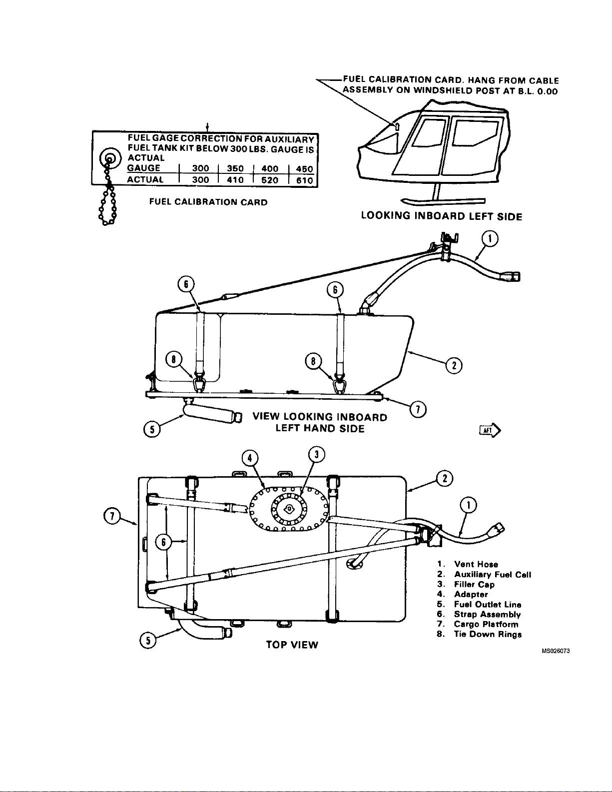
TM 55-1520-228-10
Figure 2-15. Auxiliary Fuel System
2-29
Page 76
TM 55-1520-228-10
2-24. CONTROLS AND INDICATORS.
a. Fuel Quantity Indicator. The FUEL QTY indi-
cator (figure 2-13 and 2-14) is located in the instrument
panel and displays the quantity of fuel in the fuel cell in
pounds (0 to 600 lbs.). The indicator is powered by 28
Vdc and protect by INST CLUSTER circuit breaker
FUEL QTY circuit breaker
b. Fuel Boost Caution Light. The FUEL BOOST
caution light (figure 2-13 and 2-14) is located on the caution panel and illuminates if the fuel boost pressure is
below safe operating limits when fuel boost switch is in
the ON position. The system is powered by 28 Vdc and
protected by CAUTION PANEL LTS circuit breaker.
c. Fuel Boost Pump Switch. The FUEL BOOST
switch (figure 2-13 and figure 2-14) is located in the
lower right corner of the instrument panel. The fuel
switch will be in the fuel boost position for all normal
conditions when the engine is operating and for starting. The system is powered by 28 Vdc and prote
FUEL PUMP circuit breaker.
Low fuel caution systems alert the pilot tha
in the tank has reached a specified level (capacity). Differences in fuel densities due to temperature and fuel type will vary the weigh
.
boost
cted by
NOTE
t fuel
t of fuel
remaining and actual time aircraft engine may
operate. Differences in fuel consumption rates,
aircraft altitude and operational condition of the
fuel subsystem will also affect actual time aircraft engine may operate.
,
d. Low Fuel Quantity Caution Light. The LOW
FUEL caution light, (figure 2-13 and figure 2-14), located
in caution panel, should illuminate when there is approximately 20 minutes or 65 to 98 pounds of fuel remaining.
The illumination of this light does not mean a fixed time
remains. When the 20 minute fuel caution light is on, the
fuel remaining may not be available except when the aircraft is in level or coordinated flight. The 20 minute
caution light in conjunction with a fuel boost caution light
may indicate impending fuel starvation. The system is
powered by 28 VDC and projected by Caution PNL LTS
circuit breaker.
e. Fuel Filter Caution Light. The FUEL FILTER
caution light (figure 2-13 and figure 2-14), located in the
caution panel, will illuminate when the filter in the fuel
supply line becomes partially obstructed
is powered by 28 Vdc and protected by CAUTION PNL
LTS circuit breaker. The light may illuminate momentarily when the boost pump is turned on, b
extinguish within approximately ten seconds.
. The system
ut it should
fuel
SECTION V. FLIGHT CONTROLS
2-25. DESCRIPTION.
When carrying non-rated passengers unfamiliar with operation of the helicopter, pilot should
evaluate the mission as to
advantages of stowing copilot controls or accepting the responsibility of the potential hazard
when leaving the contro
The flight control system is a positive mechanical type,
actuated by conventional helicopter controls which,
when moved, directs t
of flight. Dual flight controls are provided. The system
includes; the cyclic control stick, used for fore and aft
and lateral contro
used for vertical control; and the tail rotor anti-torque
he helicopter in various modes
l; the collective pitch control lever,
advantages and dis-
ls in place.
control pedals, used for heading control. The control forces of the main rotor fl
reduced to a near zero pounds force, to lessen pilot
fatigue, by hydraulic servo cylinders connected to the
control system mechanical l
the transmission driven hydraulic pump. Force trims
(force gradients) connected to the cyclic controls are
electrically operated
artificial control feeling into the cyclic controls and to
prevent the cyclic stick moving from a pre-set position.
2-26. CYCLIC CONTROL.
The pilot cyclic grip
lowing switches: force trim release switch, ICS switch,
and RADIO transmit switch. The cyclic control system
controls the fore,
copter. Control feel is provided by the force trim units.
mechanical units used to induce
(figures 2-3 and 2-4) contains the fol-
aft, and lateral movement of the heli-
ight control system are
inkage and powered by
2-30 Change 14
Page 77

TM 55-1520-228-10
NOTE
Removal of copilot cyclic stick can
cause pilot cyclic stick to creep
slightly aft.
a. Copilot Cyclic Stick Stowage.
NOTE
Force trim will be lost when the
electrical connector is disconnected
when stowing or removing the
copilot cyclic stick Removal is
authorized by the pilot and/or
commander (Fuel quantity gage
cannot be monitored with cyclic stick
stowed
(1) Unscrew retaining nut on cyclic stick.
(2) Secure cyclic stick on stowage pin and strap
located on the left outboard side of the center console.
b. Copilot Cyclic Stick Installation.
(1) Remove cyclic stick from stowage.
(2) Insert cyclic stick into pivot assembly on
torque tube.
(3) Secure cyclic stick in pivot assembly with
knurled nut.
C ).
copilot collective lever, located on the left of the copilot
position, contains only a twist type throttle at the forward
end of the control.
a. Copilot Collective Pitch Control Stowage.
(1) Remove the boot around copilot stick shaft.
(2) Loosen knurled nut at base of copilot stick
Remove stick.
(3) Stow stick in clips located on forward side of
copilot seat.
b. Copilot Collective Pitch Control Installation.
(1) Remove stick from stowage clips and insert
stick in jackshaft elbow assuring engagement of throttle
tube.
(2) Secure stick in elbow with knurled nut.
(3) Secure boot around stick shaft.
2-28. ANTI-TORQUE (DIRECTION) CONTROL.
Anti-torque control pedals (figure 2-3 and figure 2-4)
alter the pitch of the tail rotor blades and thereby provide
the means of directional control. Pedal adjustments are
located at the base of the pedals at floor level. Adjuster
knobs enable adjustment of pedal distance for individual
comfort.
(4) Ensure electrical connector is installed.
2-27. COLLECTIVE PITCH CONTROL.
WARNING
Do not use deck under collective for
storage. This could cause interference in the full down position.
The pilot collective pitch control is located to the left of
the pilot position and controls the vertical mode of flight.
A rotating grip-type throttle and a switch box assembly
are located in the forward end of the pilot collective pitch
lever (figure 2-3 and figure 2-4). The switch box
assembly contains the starter, governor engine idle
release and landing lights switches. Friction can be
induced into the collective system by rotating a friction
device located between the pilot and copilot seats. The
a. Deleted.
b. Deleted.
2-29. FORCE TRIMS (FORCE GRADIENT).
Force gradient devices are incorporated in the controls.
These devices are installed in the flight control system
between the cyclic stick and the hydraulic power cylinder
(servo). The devices act to furnish a force gradient of
feel to the cyclic control stick. However, these forces
can be reduced to zero by depressing the force trim
button on the cyclic stick (figure 2-3 and figure 2-4). The
gradient is accomplished by means of springs and
magnetic brake release assemblies which enable the
pilot to trim the controls, as desired, for any condition of
flight. A FORCE TRIM toggle switch is installed in the
control panel to activate the force trim system.
Change 10 2-31
Page 78

TM 55-1520-228-10
2-30. HORIZONTAL STABILIZER.
The horizontal stabilizer (figure 2-1 and figure 2-2) is
located near the center of the tail boom an is installed in
a predetermined fixed position. The horizontal stabilizer
aids in trimming the helicopter in level flight and
increases usable CG range.
SECTION VI. HYDRAULIC SYSTEM
2-32. DESCRIPTION.
The hydraulic system consists of a variable delivery
pump and reservoir, servo actuators with irreversible
valve circuits for cyclic and collective controls, a
pressure line filter, a return line filter, and a solenoid
shutoff valve. The pump is located on the transmission.
The hydraulic system provides for fully powered flight
controls during authoritative flight.
2-31. VERTICAL FIN.
The vertical fin is located to the right of the tail rotor and
is installed in a predetermined fixed position.
2-33. CONTROL
A hydraulic system switch (HYD BOOST) is located on
the lower right portion of the instrument panel and
controls the activation and deactivation of the hydraulic
system. (Refer to figure 2-13 and figure 2-14.)
2-34. CAUTION INDICATOR.
A caution indicator is located on the caution panel to
indicate when hydraulic pressure is low (figure 2-13 and
figure 2-14).
2-32 Change 10
Page 79

SECTION VII. POWER TRAIN SYSTEM
TM 55-1520-228-10
2-35. TRANSMISSION.
The transmission is mounted on the cabin roof deck,
forward of the power plant. The transmission transfers
engine power to the main rotor through the mast assembly . The tail rotor is driven through the freewheeling unit,
tail rotor driveshafts and tail rotor gearbox. Transmission lubrication is provided by a pump, relief valves, two
each filters, spray jets, temperature bulb, and an oil
cooler. The pump is a constant volume type driven by
the accessory gear. An oil level sight gage is located on
the right side of the transmission case. A breather type
filler cap and two electrical magnetic chip detector drain
plugs are incorporated. The transmission also furnishes
lubrication for the freewheeling unit mounted in the engine accessory gearbox. Transmission oil is cooled by
the oil cooler blower.
2-36. PYLON SUPPORT STRUCTURE.
a. The OH-58A/C has a design feature called a
focused pylon mounting system for its pylon. This support concept differs from conventional four or five point
spring mounting arrangements as follows:
(1) The pylon bi-pod supports aim or focus pylon input loads at the fuselage vertical center of gravity .
The purpose is to reduce cabin vibration by eliminating
pylon induced rolling moment about the center of gravity.
is mounted so that it “rides” inside the square metal
opening of the transmission mount support.
c. The isolation mount is used to dampen pylon to
fuselage vibration and limit pylon rock. Movement of the
transmission and isolation mount is limited by means of
the drag pin (spike) which extends down into the transmission mount support mounted on the deck.
d. Contact between the drag pin and the transmission mount produces a noise known as spike knock.
2-38. FREEWHEELING ASSEMBLY.
The freewheeling unit is mounted in the accessory gearbox. Engine power is transmitted through the freewheeling unit to the main driveshaft and tail rotor driveshafts
to provide power to the main and tail rotors respectively .
During autorotation the freewheeling unit provides engine disconnect and transmission drives the tail rotor.
2-39. TAIL ROTOR GEARBOX.
The gearbox is located near the vertical fin and provides
a 90 degree change of direction of the tail rotor driveshaft. A breather type filler cap, electrical chip detector
drain plug and an oil level sight gage are provided.
2-40. DRIVESHAFTS.
(2) Rigid mounting in the vertical plane mini-
mizes vertical vibration.
(3) Vibration should not increase with mount
aging as is possible with conventional spring mounted
pylon supports.
b. The elastomeric mount provides pylon static
centering.
2-37. PYLON SUSPENSION SYSTEM.
a. The main transmission is supported and at-
tached at its lower rear section by an isolation mount.
Bolted to the lower aft part of the transmission case is
the drag pin which bolts to the elastomeric isolation
mount.
b. The drag pin has a metal pin which is commonly
referred to as the spike. The drag pin or spike physically
a. Main Driveshaft. The main driveshaft connects
the engine output to the transmission.
b. T ail Rotor Driveshaft. The tail rotor driveshaft is
made up of four sections; the forward short shaft, the oil
cooler fan shaft, the aft short shaft, and the long shaft.
2-41. INDICATORS.
a. T ransmission Chip Detectors. There are three
chip detectors located within the transmission lubricating system. Two electrical chip detectors are located on
the base of the transmission and are wired to the XMSN
CHIP DET caution light and the MASTER CAUTION
light. One magnetic chip detector is located on the freewheeling unit and is not connected to the caution lighting
system. All three are provided to give evidence of ferrous metal particles in the transmission lubrication system.
Change 11 2-33
Page 80

TM 55-1520-228-10
b. Tail Rotor Gearbox Chip Detector. The chip
detector is located in the lower section of the tail rotor
gearbox. The chip detector is wired to the T/R CHIP DET
caution light and the MASTER CAUTION light. The caution light is activated when a sufficient amount of metal
particles has been collected on the chip detector to close
the circuit.
c. Transmission Oil Pressure Warning
Light. The XMSN OIL PRESS warning light (figure
2-13 and figure 2-14) is located in the upper center
section
panel. The XMSN OIL PRESS light will illuminate steady
until oil pressure is above 36 psi. Normal operating pressure is 30 to 60 psi with warning light actuation at 30 $
A , and upper right corner C of the instrument
SECTION VIII. MAIN AND TAIL ROTOR GROUPS
2-42. MAIN ROTOR.
The main rotor assembly is a two blade, semi-rigid, seesaw type rotor called an underslung feathering axis hub.
The blades are mounted in the hub assembly grips with
blade retaining bolts which have hollow shanks for
installation of weights to balance the hub and blade
assembly. Pitch change and pillow block bearings are
lubricated with grease. The rotor blades are all metal,
consisting of an extruded aluminum alloy nose block,
aluminum alloy trailing edge and an aluminum honeycomb filler. The main rotor is driven by the mast which
is connected to the transmission. The rotor RPM is governed by the engine RPM during powered flight. The
rotor tip path plane is controlled by the cyclic stick. The
rotor pitch is controlled by the collective lever.
2 psi on decreasing pressure. The transmission oil pressure switch is located on the left side of the cabin roof
near the transmission. The light is protected by the CAUTION PNL LTS circuit breaker.
d. Transmission Oil Temperature Warning
Light. The XMSN OIL HOT warning light (figure 2-13
and figure 2-14) is located in the upper center section
,and upper right corner C of the instrument panel. The
XMSN OIL HOT light will illuminate when temperature
is 110_C or above. The transmission oil temperature
sensor is located on the transmission oil filter head. The
light is protected by the CAUTION PNL LTS circuit
breaker.
marked with an R. The indicator is powered by a
tachometer generator mounted on and driven by the
transmission and is independent of the helicopter electrical system.
protected by the DUAL TACH circuit breaker.
C Model aircraft require 28 VDC and are
A
2-44. RPM WARNING SYSTEM.
A ROTOR RPM warning system is installed to provide
a visual and audio indication of low rotor RPM. A RPM
sensor is connected to the rotor tachometer. Power is
supplied from the CAUTION PNL LTS circuit breaker
and connections are made to the ROTOR RPM warning
light and to a tone generator which provides an audible
tone in the crews headsets. The warning system is activated when the rotor RPM drops below 95% $ 1.4%.
2-43. MAIN ROTOR RPM INDICATOR.
CAUTION
The same audio tone is used for both
the rotor rpm warning and engine out
warning. Check the visual indicators
to determine corrective action ne-
cessary.
The rotor tachometer indicator (figure 2-13
2-14
C ) is part of the dual tachometer and is located on
the instrument panel. The rotor RPM reading is indicated on the inner scale and the pointer needle is
2-34 Change 11
A , figure
2-45. TAIL ROTOR.
The tail rotor is driven by the inner shaft of the freewheeling unit through tail rotor driveshaft and the tail rotor
gearbox. The tail rotor hub and blade assembly consists
of an aluminum alloy forged yoke and aluminum alloy
blades. The spherical bearings provide for pitch change
of the blades. The hub and blade assembly are mounted
on the tail rotor gearbox shaft by means of a splined
trunnion, mounted in bearings in the yoke, to provide a
flapping axis for the assembly . The tail rotor gearbox has
a breather type filter cap, electrical chip detector and oil
level sight gage, all accessible from ground level. Tail
rotor blade pitch is controlled by the anti-torque pedals.
Page 81

SECTION IX. UTILITY SYSTEM
TM 55-1520-228-10
2-46. PITOT HEATING SYSTEM.
a. Description. The pitot heater is installed on
the pitot head and functions to prevent ice forming in
the pitot tube. Electric power for the pitot heater operation is supplied from the 28 VDC helicopter electrical
system. Circuit protection is provided by a 5 ampere cir-
SECTION X. HEATING AND VENTILATION
2-47. BLEED AIR HEATING SYSTEM.
a. Description. The bleed air heater is installed
in the equipment compartment aft of the electrical
behind the passenger seat. A HTR switch (figure 2-12)
located on the overhead console actuates the heater.
The pilot may select air temperature by means of a
HEAT control knob (figure 2-17) located above and aft
of his head. This knob operates a control cable in the
cabin roof to adjust an air temperature se
in the heater discharge duct. Adjusting the sensor mixes
the fresh and bleed air to obtain the air temperature
selected by the pilot. The bleed air hea
connected to windshield defog nozzles at the bottom of
the forward windshield through blowers mounted in the
fuselage nose. The blowers are ac
VENT circuit breaker switch (figure 2-12) located on the
overhead console to increase airflow velocity over the
windshield. Lower nose window
and automatic when HTR switch is turned on. Outside
fresh air from an intake on the top of the fuselage
nose is directed through the
mounted on the lower windshield frame. A VENT PULL
control on the right side of the instrument panel (figure
2-16) opens and closes th
windshield defog nozzles
e fresh air intake.
nsor mounted
ting ducts are
tivated by DEFOG &
defog is continuous
shelf
cuit breaker switch on the overhead console. The pitot
heater is controlled by a switch located on the overhead
console (figure 2-12) labeled PITOT HTR.
b. Operation. The pitot heater switch should be
in PITOT HTR position to prevent ice forming in pitot
tube. To shut off pitot heater, position switch to OFF.
b. Operation. A circuit breaker switch labeled
HTR on the overhead console (figure 2-12) actuates a
solenoid valve. The switch in the ON position permits
air from the engine compressor section to pass th
the bleed air nozzle. A venturi working in conjunction
with the bleed air nozzle draws in outside air through
the outside air vent. Bleed air and outside air
the mixing valve where a sensor determines the mixing
ratio produce the desired temperature. Bleed air forces
heated air through the duct system to re
the seat and/or to the defroster nozzles. Temperature
is regulated by a manual control knob labeled HEAT
located above and to the rear of the pi
connected to a variable remote sensor in the heater
compartment. The sensor has a bimetallic element
which controls the mixing valve
vent system is installed in the nose and consists of a
ram air intake, two blower fans, defroster nozzles and
ducts. The bleed air system is
defogging and vent system. Outside air flow to the
cabin and defogging nozzles is controlled by manual
push-pull type controls la
located on each side of the instrument panel (figure
2-16). The blowers direct air to the defogging nozzles
and are controlled by a 5
labeled DEFOG & VENT, on the overhead console.
(Refer to figure 2-12).
. The defogging and
also connected to the
beled VENT and DEFOG
AMP circuit breaker switch,
gisters under
lot’s head, and
rough
is fed into
Change 10 2-35
Page 82
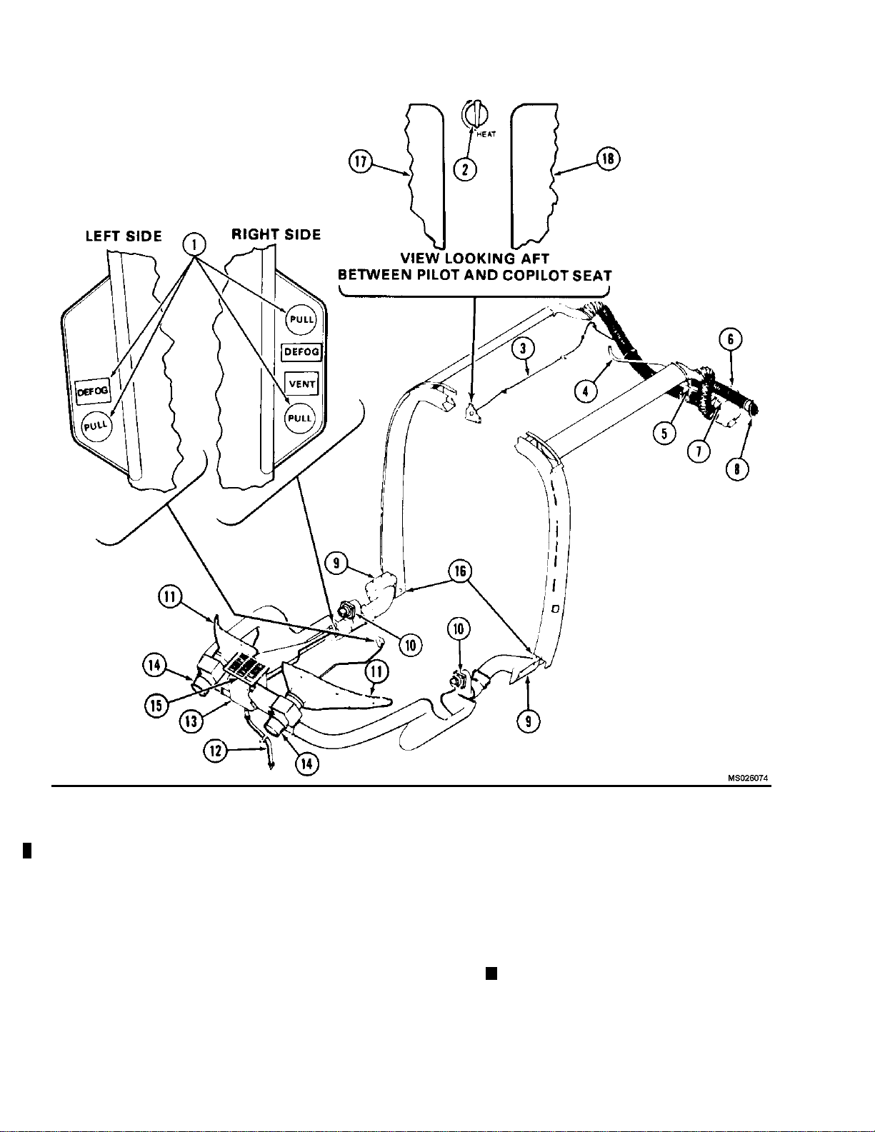
TM 55-1520-228-10
1.
Vent and Defog Control
(Instrument Panel)
2.
3.
4. Bl
5.
ter Control Knob
Hea
Heat Control Cable
eed Air Tube
Mixing Valve 12. Plenum Drain 18.
7.
Remote Sensor
8. Fresh Air Inlet 15.
9. Post Plenum 16. Air Distribution Vents
10. Air Distribution Valves
.
11
Windshield Defog Nozzle
6. Plenum 13. Plenum Valve Assembly
Figure 2-16. Heating and Ventilation
2-36
Change 14
14.
Ventilation and Defoggin g Blower
Ram Air In ta ke Grill
Cargo / Passenger Area
.
17
PilotSeatBack(REF)
Copilot Seat Back (REF)
(Sheet 1 of 2)
A.
Page 83
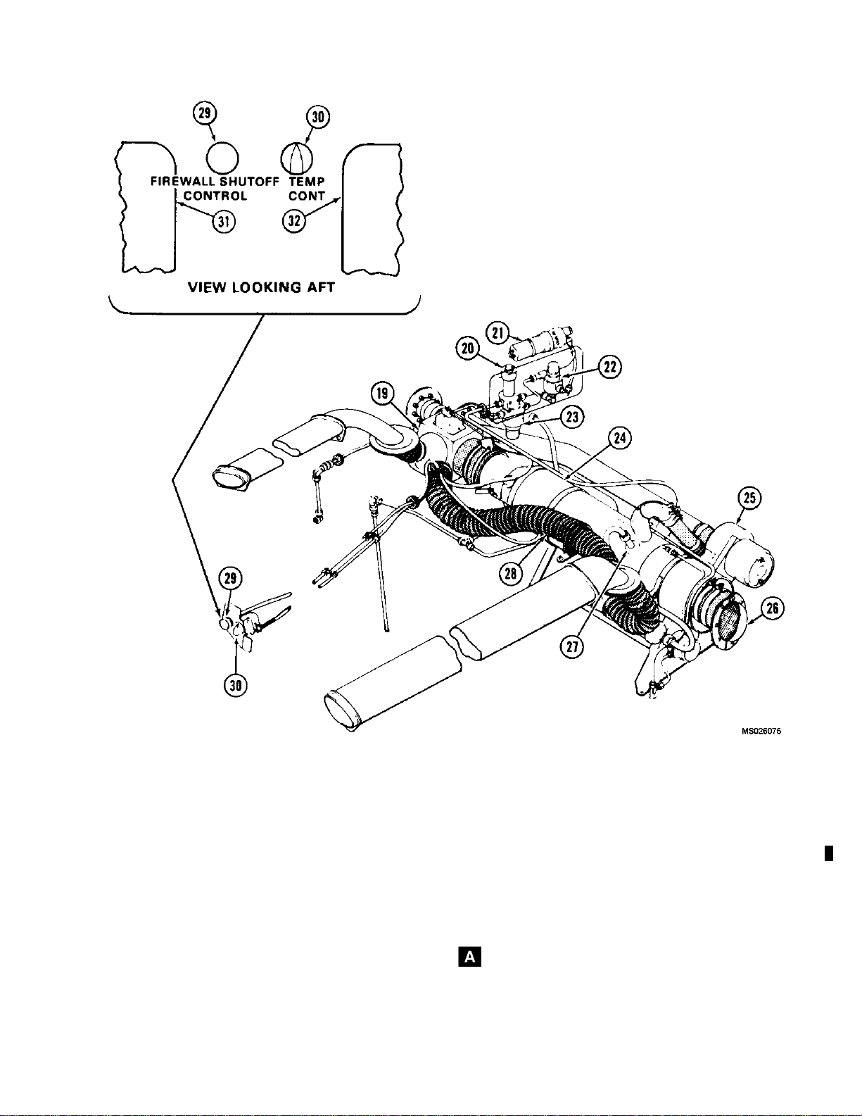
TM 55-1520-228-10
19.
20.
21. Fuel Pump 28. Duct
22.
23. Fuel Filter 30.
24. Heater 31.
25.
Combustion Heater Plenum
Fuel Shutoff Valve
Fuel Pressure Relief Valve
Combustion Blower
Figure 2-16. Heating and Ventilation (Sheet 2 of 2)
26. Fresh Air Inlet
27. Igniter Plug
29.
32.
Firewall Shutoff Control
Heat Control Knob
Pilot Seat Back
Copilot Seat Back
Change 14 2-37
Page 84
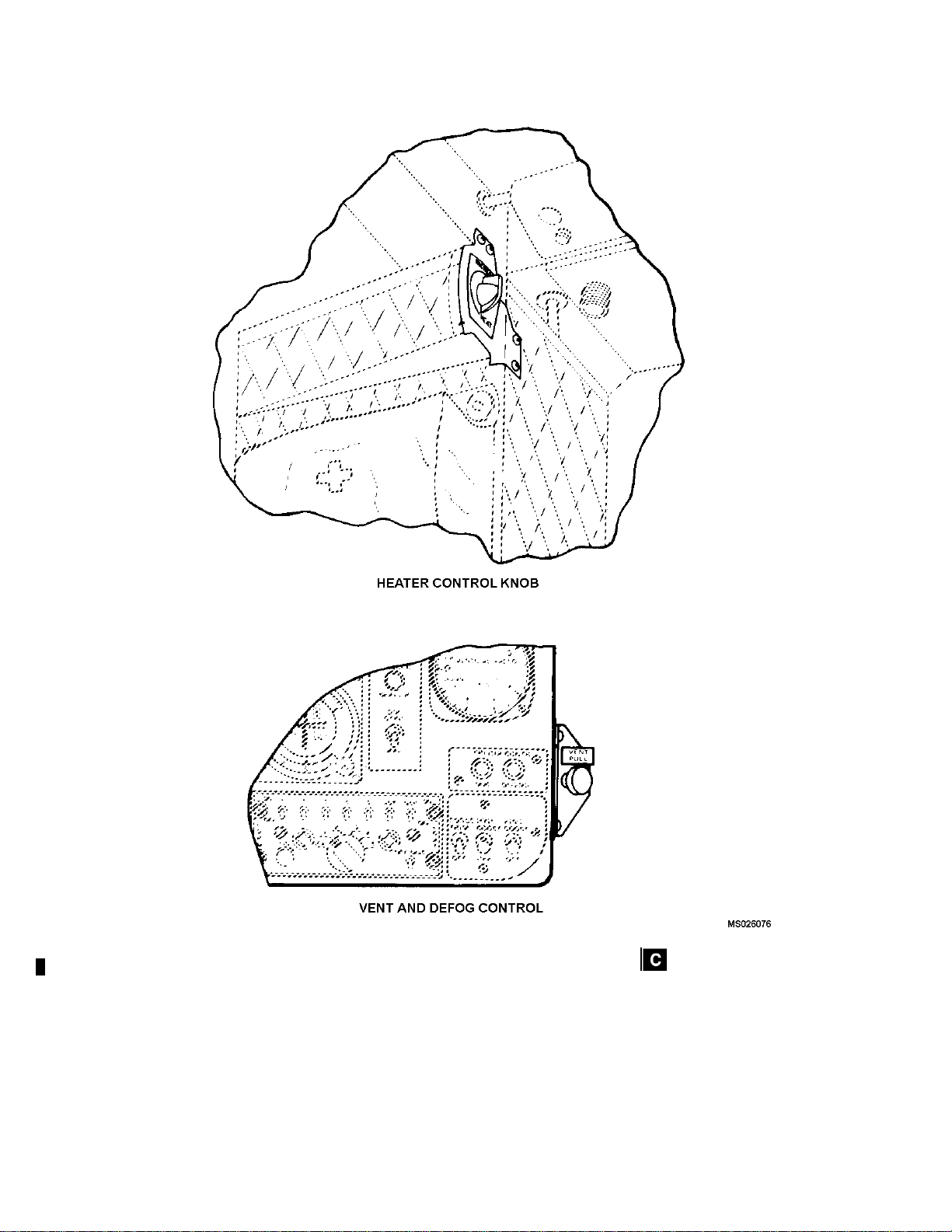
TM 55-1520-228-10
2-38 Change 12
Figure 2-17. Heater Control and Vent Pull Knobs
Page 85

A COMBUSTION HEATER.
2-48.
TM 55-1520-228-10
(5) BAT switch - BAT.
a. Description. A combustion heater is installed on
the electrical shelf behind the passenger seat, on
helicopter serial Nos. 70-15263 thru 70-15278, in the aft
equipment compartment. Fuel for heater operation is
supplied by the helicopter fuel system and routed
through the heater fuel filter, pump, relief valve, and
shutoff valve. Ignition is supplied by a heater mounted
ignition assembly which converts 28 volts DC to high
voltage, producing a continuous spark during heater
operation. Air is supplied by a blower through a port on
the right side of the helicopter and routed to the
combustion chamber. Heater exhaust gasses are piped
overboard through a shrouded exhaust flue. Heated air
is distributed by a heater mounted ventilating air blower
and routed through ducts to the forward and aft cabin
compartments. Two adjustable distribution valves are
provided in the pilot compartment and two fixed
openings for the passenger compartment. Controls for
heater starting are located on the overhead panel and
two controls are mounted on the vertical column on pilot
seat back. The left side control is for temperature and
the right side control operates the heater shutoff valve in
the event of fumes, fire, or heater malfunction. A heater
fail light is mounted on the console and will indicate
heater malfunction. Consumption of fuel is 3.5 gallons
per hour for 30,000 BTU heater and 4.5 gallons per hour
for the 50,000 BTU heater. (Refer to figure 2-16.)
b. Combustion Heater Pre-Start Check.
(1) FUEL PUMP circuit breaker - In.
(2) HTR PWR circuit breaker - In.
(3) HTR CONT circuit breaker - In.
(6) FUEL VALVE - ON
(7) HEAT-OFF-VENT switch - OFF.
c. Normal Operation.
(1) HEAT-OFF-VENT switch ON. Check that
combustion air and vent blowers operate and HEATER
FAIL caution light is on.
(2) HTR START switch Press and hold, Ignition
should occur within 5 to 10 seconds HEATER FAIL
caution light should go off.
(3) TEMP CONT knob Regulate for desired
temperature.
(4) HEAT-OFF-VENT switch OFF, to shut down
heater.
NOTE
HEAT-OFF-VENT switch in OFF
position, the combustion air and vent
blowers will continue to operate,
cooling and purging the heater, and
will cut off automatically when the
heater has cooled if manual cooling
and purging is desired place switch
in VENT position, then return switch
to OFF.
d. Emergency Shutdown.
(1) FIREWALL SHUT-OFF CONTROL knob
- Release and pull out.
(4) FIREWALL SHUT-OFF CONTROL-- In.
(2) HEAT-OFF-VENT switch - OFF.
2-39
Page 86

TM 55-1520-228-10
SECTION XI. ELECTRICAL POWER SUPPLY AND DISTRIBUTION SYSTEM
2-49. DIRECT CURRENT PRIMARY POWER.
The OH-58A/C helicopter is equipped with a 28-volt
direct current dual bus (essential and non-essential)
system supplied by a starter-generator and battery
(figure 2-18). Components of the direct current power
system include battery, starter-generator, voltage
regulator, relays, switches, and circuit breakers. All
circuits in the electrical system are single wire with
common ground return. The negative terminals of the
starter-generator and the battery are grounded to the
helicopter structure. In the event of generator failure,
with the NON-ESS BUS switch in the NORM position,
the non-essential bus is automatically deactivated. The
battery then supplies power to the essential bus load.
The non-essential bus may be manually reactivated by
placing the NON-ESS BUS to the MAN position. In the
event of engine failure, generator power will be lost.
a. Indicators and Controls.
(1) DC System Indicator. The ammeter is
mounted in the instrument duster on the instrument
panel and indicates the ampere load being used. The
circuit is protected by two circuit breakers, labeled
LOADMETER in the aft electrical compartment.
(2) DC Power Control. The DC power is
controlled by the BAT switch, GEN switch, NON-ESS
BUS switch, and circuit breakers labeled GEN & BUS
RESET and GEN FIELD.
(3) Battery Switch. The Battery switch is
located in the overhead console and is a two-position
toggle switch, labeled BAT and OFF. Battery electrical
power is supplied to the helicopter electrical system
when the switch is in the BAT position. When the switch
is in the BAT position, it closes the circuit to the
actuating coil of the battery relay and battery power is
then delivered from the battery to the essential bus.
When the switch is placed in the OFF position, it opens
the circuit to the actuating coil of the battery relay and no
power is delivered from the battery to the essential bus.
(4) Generator Switch. The generator switch is
located on the overhead console and is a three-position
switch. This switch is labeled GEN in the forward
position, OFF in the center position, and RESET in the
aft position. The RESET position is spring-loaded to
return to the OFF position when released. Therefore, to
reset the generator, the switch must be held in RESET
position momentarily, and then moved to the forward
position.
(5) Non-Essential Bus Switch. The non-
essential bus switch is located in the overhead console
and is a two-position switch labeled NON-ESS BUS
NORM and MAN. When the switch is in the NORM
position, power is supplied to the non-essential bus
provided the generator is operating or when external
power is applied. When the switch is in the MAN
position, power is supplied to the non-essential bus
regardless of generator operation.
b. Circuit Breakers. The DC circuit breaker panel
(figure 2-12) is located in the overhead console. Each
individual circuit breaker is dearly labeled for particular
electrical circuits protected. In the event a circuit is
overloaded, the circuit breaker protecting that circuit will
deactivate. The circuit is reactivated by pushing the
circuit breaker button.
c. External Power Receptacle. During ground
operations, external power may be connected to the
electrical system through an external power receptacle
located on the lower right side of the helicopter just aft of
the rear landing gear crosstube. The GEN and BAT
switches should be in the OFF position when external
power is connected. The external power relay closes
automatically and connects the ground unit to the
essential and non-essential buses. A GPU power of 300
to 750 amperes and 28 vdc is recommended.
d. Auxiliary Power Receptacle. The auxiliary
power receptacle is mounted on a bulkhead aft of the
copilot seat and provides power take off of 28 Vdc to
operate miscellaneous auxiliary equipment. The circuit
is powered by 28 Vdc essential bus and is controlled and
protected by AUX RECP circuit breaker switch on the
overhead console.
2-40 Change 10
Page 87
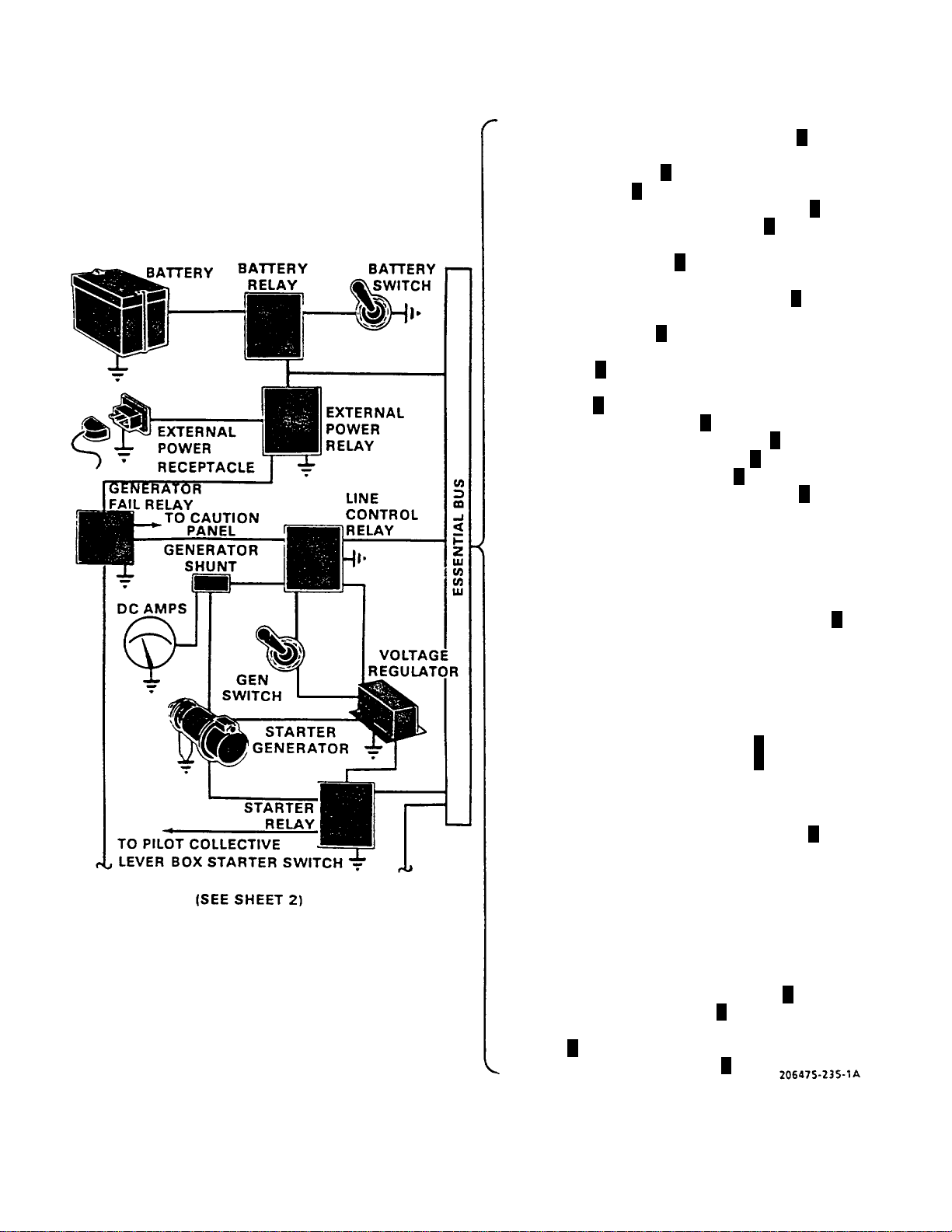
(Fig
)
TM 55-1520-228-10
(Figure 2-18 Sheet 1 of 2)
ure 2-18 Sheet 2 of 2
NAV POSITION LIGHTS (NVG POS LTS)
SRCH/LANDING LT CONTROL
(SRCH LT CONT)
AMMETER(AMM)
FUEL QUANTITY INDICATOR (FUEL QTY)
DUAL TACHOMETER (DUAL TACH)
GAS PRODUCER TACHOMETER
(GAS PROD TACH)
TURBINE OUTLET TEMPERATURE
INDICATOR (TURB OUTLET TEMP)
ENGINE OIL TEMPERATURE INDICATOR
(ENG OIL TEMP)
PRIMARY DIRECTIONAL CONTROL (PRI DRI
CONTR)
TRANSMISSION OIL PRESSURE (XMSN OIL
PRESS)
CONSOLE LIGHT (CSL LT)
CONUS NAVIGATION (CONUS NAV)
ALTIMETER VIBRATOR (ALT VIB)
RADAR ALTIMETER (RDR ALT)
RADAR WARNING SYSTEM (RDR WRN)
GENERATOR FIELD (GEN FIELD)
GENERATOR & BUS RESET (GEN & BUS RESET)
CAUTION PANEL (CAUTION PNL LTS)
SIGNAL LIGHT (SIGNAL LT)
INSTRUMENT LIGHTS (INST LTS)
ANTI-COLLISION LIGHTS (ANTI-COLL LTS)
SRCH/LANDING LT POWER (SRCH LT PWR)
ENGINE OIL BYPASS (ENG OIL BYPASS)
GOVERNOR CONTROL (GOV CONT)
FUEL BOOST PUMP (FUEL PUMP)
STARTER (START ENG)
IGNITER AND AUTO RELIGHT (IGN ENG)
ENGINE ANTI-ICE (ENG DEICE)
ATTITUDE SYSTEM (ATTD TURN)
ATTITUDE SYSTEM (ATTD HRZN)
FORCE TRIM (FORCE TRIM)
HYDRAULIC BOOST SOLENOID (HYD BOOST
SOL)
INSTRUMENT CLUSTER (INST CLUSTER)
IFF (IFF)
ADF (ADF)
UHF (UHF)
ICS (ICS)
ARMAMENT (ARMT)
ARMAMENT POWER (ARMT PWR)
PITOT HEATER (PITOT HTR)
AUXILIARY POWER (AUX RECP)
PROXIMITY WARNING (PROX WARN)
LANDING LIGHTS (LDG LTS)
TURN AND SLIP INDICATOR (TURN & BANK
IND)
IFF COMPUTER (IFF CMPTR)
C
C
A
C
C
C
C
C
C
C
A
A
C
C
C
C
C
C
C
C
C
A
C
Figure 2-18. Electrical System Schematic (Sheet 1 of 2)
Change 10 2-41
Page 88
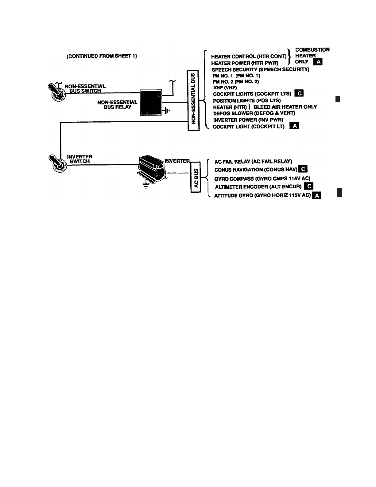
TM 55-1520-228-10
Figure 2-18. Electrical System Schematic (Sheet 2 of 2)
2-50. ALTERNATING CURRENT POWER
SUPPLY.
The OH-58A/C helicopter is equipped with a solid state
inverter powered from the non-essential 28 volt DC bus
through a 5 ampere INV PWR circuit breaker and is
manually controlled by an INV switch (figure 2-12). The
inverter delivers 115 volt AC 400 Hz to the 115 volt AC
bus. A caution panel segment INST INVERTER will
illuminate when AC power is lost.
a. Controls. The AC power is controlled by the INV
switch and AC circuit breakers. The inverter switch is
located in the overhead console and is a two-position
toggle switch labeled INV and OFF. AC electrical power
is provided to the electrical system when the switch is in
the forward position. DC power to the inverter is
supplied by the non-essential bus; therefore, to have AC
power, electrical power must be available at the nonessential bus. When the switch is in the OFF position it
opens the circuit to the inverter.
b. Circuit Breakers. The AC circuit breakers are
on the aft end of the overhead console. In the event of a
circuit overload, the circuit breaker protecting that circuit
will pop out. The circuit is reactivated by pushing in the
circuit breaker button.
2-42 Change 10
Page 89
SECTION XII. LIGHTING
TM 55-1520-228-10
2-51. POSITION LIGHTS.
The position lights consist of three lights (figure 2-1 and
figure 2-2). A green light is located on the right horizontal stabilizer tip, a red light on the left horizontal stabilizer
tip, and a white light on the aft end of the tailboom. Electrical power is supplied from the 28-volt DC non-essential bus. Circuit protection is provided by the POS LTS
circuit breaker on the overhead console. The position
lights are controlled by the POS LTS switch on the overhead console (figure 2-12). The switch is a three-position toggle switch with BRT (forward) DIM (center) and
OFF (aft) positions.
2-52. NVG POSITION LIGHTS.
Five, white IR position lights (NVG position lights) are
mounted on the aircraft. Two forward NVG position
lights (figure 2-2) are mounted forward of t
ing antenna on both sides of the aircraft. Two lower
NVG position lights (figure 2-2) are mounted forward
of the APR-39 antenna support. One aft NVG
light is located on top of the tail light support assembly.
Power for NVG position lights is provided by the NVG
POS LTS circuit breaker (figure 2-1
the NVG position lights is controlled by a five-position
rotary switch, NVG POS LTS, (figure 2-12) located on
theoverheadconsole. Inpositio
minumum intensity, in position BRT, the lights are at
maximum intensity.
2-53. ANTI-COLLISION LIGHTS.
The anti-collision lights a
gine cowling and one centered at the lower section of
the fuselage aft of the avionics compartment. Electrical power for the anti-col
28-volt DC electrical system essential bus. The anticollision light switch is located on the overhead console (figure 2-12). Th
type labeled ANTI-COLLISION LTS and OFF. The forward position energizes the anti-collision light circuit.
re located one on top of the en-
lision lights is provided by the
e switch is a two-position toggle
n 1, the lights are at
he FM hom-
position
2). Operation of
Float equipped helicopters have lower light relocated
from boom station 88.0 to boom station 103.0.
2-54. LANDING LIGHTS.
IR/White (Dual) Landing/Searchlight. A dual light as-
sembly with a white light on one side and IR light on the
other side is mounted in the lower nose section of the
helicopter (figure 2-2).
Do not illuminate IR light with light assembly
fully retracted. Doing so may cause light to
overheat, resulting in damage to electrical components of the helicopter.
Power for the light assembly is provided by the SRCH
LT CONT and SRCH LT PWR circuit breakers. One
three-position switch and one four-positi
cated on the pilot collective lever (figure 2-4), are used
to operate the light assembly.
DELETED
The three-position switch LDG LT (ON
trols illumination of the white light (ON position) and the
IR light (NVG position).
NOTE
White light will automatically e
light rotates 90° right or left of center, if extended
less than 60°.
The four-position switch LD
vides extension, 360° rotation and retraction.
G LT (EXT-RETR-L-R) pro-
on switch, co-lo-
-NVG-OFF) con-
xtinguish when
Change 12 2-43
Page 90

TM 55-1520-228-10
2-55. DELETED.
2-56. INSTRUMENT LIGHTS.
The instrument lights are all on one circuit and are controlled by a rheostat switch labeled INST LTS on the
overhead console (figure 2-12). Clockwise rotation of
the rheostat knob activates the instrument panel circuit
and increases brilliance. Counterclockwise rotation of
the knob dims, with final movement (OFF) deactivating
the electrical circuit from the essential bus.
NVG compatible bezel lights and postlights provide
instrument panel lighting (figure 2-4). The instrument
panel lighting is controlled by the INST LT rheostat
control (figure 2-12) and is powered by the INST LTS
circuit breaker.
2-57. CONSOLE LIGHTS.
The console lights are all on one circuit, and are
trolled by a rheostat switch labeled CONSOLE LTS on
the overhead console (figure 2-12). Clockwise rotation
of the rheostat knob activates the console pan
and increases brilliance. Counterclockwise rotation of
the knob dims, with final movement (OFF) deactivating
the circuit, located on the essential b
a. Night Vision Features (for Flights Using Night
Vision Goggles (NVG)). A hinged light f
tached to the instrument panel so it can be adjusted
over the ROTOR RPM warning light of the warning panel
us.
con-
el circuit
ilter is at-
(figure 2-13, items 8 and 9) for flights using NVG, and
adjusted away from the ROTOR RPM warning light for
flights not using NVG. A hinged light filter is also attached to the instrument panel for the other warning
lights, and master caution lights for use in the same
manner.
b. NVG-compatible panel lights provide lighting
of the ICS boxes KY28 and the ADF REVR located in
the aircraft. The console lighting is controlled by the
CONSOLE LT rheostat (figure 2-12) and is powered by
the CSL LT circuit breaker.
2-58. SIGNAL LIGHT RECEPTACLE.
A plug-in type receptacle (figure 2-12) for a hand held
signal light, is located at the aft end of the overhead
console. Power is supplied from the essential bus.
2-59. COCKPIT UTILITY LIGHT.
a. Cockpit Utility Lights. Two cockpit utility
lights are located within easy reach of either cr
ber. One is located on the center post and the other
on the overhead center beam behind the copilot. One
has a light filter for use with flights using NV
necessary. The lights may be hand held or positioned in
their holder for direct beam direction. A rheostat switch
is part of each light assembly. Power is
the non-essential bus through the COCKPIT LTS circuit
breaker.
b. Supplementary NVG-compatible cockpit light-
ing is provided by a utility light and three floodlights. The
ew mem-
Gwhen
supplied from
2-44 Change 12
Page 91

TM 55-1520-228-10
u tility lig h t is a tta ch e d to a fle xib le g oo se n ec k ex te ns ion
mounted on the centerpost between the pilot and copilot seats (figure 2-4). The flexible gooseneck holds the
u tility lig ht in the p o sitio n se le cte d b y t he pilo t or co p ilot.
An e xte n sio n c ord allo ws re m ov al o f th e u tility lig ht from
the gooseneck for manual us e. The light is equipped
with a self-contained rheostat and has a rheostat override pushbutton that provides full lamp output regardles s
of knob setting. Power for the light is provided by the
COCKPIT LTS circuit breaker. Three NVG-compatible
floodlights are mounted on the glareshield (figure 2-4).
F loo d ligh t inten sity is c on tro lled b y th e CO NSO L E LT
rheostat. The floodlights are powered by CSL LTS circuit breaker (figure 2-12).
NVG-compatible flip filters are mounted next to the master caution, caution advis ory, RPM, and radar warning
indicators (figure 2-13 and figure 2-14). The filters are
positioned closed for NVG flight only.
2-60. N VG-COMPATIBLE FILTE RS.
N V G -co m p atible flip filte rs a re to re ma in in th e
open pos ition (unfiltered) during day flight and
night flight without night vision goggles.
SECTION XIII. FLIGHT INSTRUMENTS
2-61. AIRSPEED INDICATOR.
The airspeed indicator (figure 2-13 and figure 2-14) displays the air speed of the helicopter indicated in knots.
The airspeed is obtained by measuring the
between impact air pressure from the pitot tube and the
static air pressure from the static ports.
2-62. AAU-31/A PNEUMATIC ALTIMETER.
1. Description. The AAU-31/A pneuma
counter-drum-pointer altimeter is a precision pressure
altimeter (figure 2-14). Pressure altitude is displayed
by a 100-foot drum and a single poin
hundreds of feet on a circular scale, with 50’ center
markings. Below an altitude of 10,000 feet, a diagonal
warning symbol will appear on
A barometric pressure setting knob is provided to insert
the desired altimeter setting in inches of Hg. A DC powered vibrator operates insid
craft power is on.
2. Operation
a Normal Operation. The ALT VIB
ALT AAU 31/32A
altimeter indicates p
barometric pressure level as selected by the pilot. A
vibrator, powered by the DC essential bus, is contained
in the altimeter an
warmup prior to checking or setting the altimeter.
circuit breaker must be in. The
neumatic altitude reference to the
d requires a minimum of one minute
the 10,000-foot counter.
e the altimeter whenever air-
difference
tic
ter indicating
or
b Abnormal Operation. If the altimeter’s i
ternal vibrator becomes inoperative due to internal failure of DC power failure, the pointer and drum may momentarily hang up when passing from “9” t
(climbing) or from “0” through “9” (descending). This
hang-up will cause lag, the magnitude of which will depend on the vertical velocity of the ai
tion in the altimeter. Pilots should be especially watchful for this type failure when the minimum approach altitude lies within the “8” — “1” par
1800-2100, etc.).
2-62.1. ALTITUDE ENCODER/PNEUMATIC
ALTIMETER AAU-32/A
a. Description. The AAU-32/A pneumatic
counter-drum-pointer altimeter is a self-contained
unit which consists of a pre
combined with an altitude encoder (figure 2-18.1). The
display indicates and the encoder transmits, simultaneously, pressure altitud
on the altimeter by a 10,000 foot counter, a 1,000 foot
counter and a 100 foot drum. A single pointer indicates
hundreds of feet of a c
markings. Below an altitude of 10,000 foot a diagonal
warning system will appear on the 10,000 foot counter.
A barometric press
the desired altimeter setting in inches of Hg. A DC
powered vibrator operates in-
WARNING
n-
hrough “0”
rcraft and the fric-
t of the scale (800-100,
cision pressure altimeter
e reporting. Altitude is displayed
ircular scale, with 50 foot center
ure setting knob is provided to insert
Change 4 2-45
Page 92
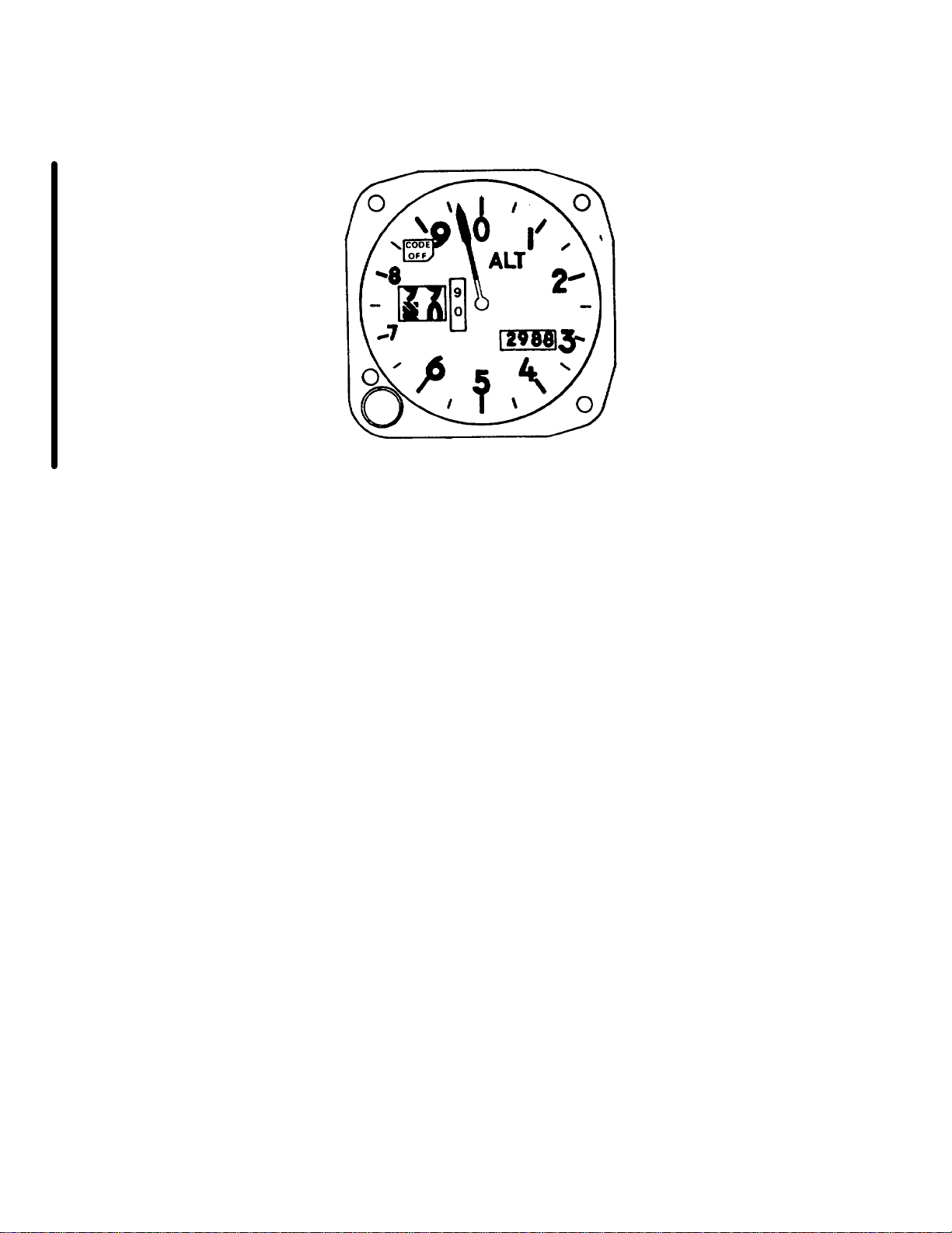
TM 55-1520-228-10
Figure 2-18.1. AAU-32/A Altitude Encode/ Pneumatic Altimeter
2-46 Change 4
Page 93

TM 55-1520-228-10
side the altimeter whenever the aircraft power is on. The
vibrator is powered through the ALT AAV31/32A[A] or
AL T VIB[C] circuit breaker . The encoder is DC powered
with the vibrator through the ALT AAU31/32A circuit
breaker [A] or separately AC powered through the AL T
ENCDR circuit breaker [C]. If power to the altitude encoder is lost, a warning flag placarded CODE OFF will
appear in the upper left portion of the instrument face
indicating that the altitude encoder is inoperative and
that the system is not reporting altitude to ground stations. The CODE OFF flag monitors only the encoder
function of the altimeter. It does not indicate transponder
condition. The altitude reporting function may be inoperative without the AAU-32/A CODE OFF flag showing,
in case of the transponder failure or improper control
settings. It is also possible to get a “good” MODE C test
on the transponder control with the CODE OFF flag
showing. Display of the CODE OFF flag only indicates
an encoder power failure or a CODE OFF flag failure. In
this event, check that encoder power is available and
that the circuit breakers are in. If the flag is still visible,
radio contact should be made with a ground radar site
to determine whether the altitude reporting function is
operative, and the remainder of the flight should be conducted accordingly.
when passing from 9 through 0 (climbing) or from 0
through 9 (descending). This hang-up will cause lag, the
magnitude of which will depend on the vertical velocity
of the aircraft and the friction in the altimeter.
(b) If the CODE OFF flag is visible, the encoder power is not available, the circuit breaker is not in,
or there is an internal altimeter encoder failure.
(c) If the altimeter indicator does not correspond within 70 feet of the field elevation (with proper
local barometric setting) the altimeter needs rezeroing
or there has been an internal failure.
(d) If the baroset knob binds or sticks, abnormal force should not be used to make the setting as
this may cause internal gear failure resulting in altitude
errors. Settings can sometimes be made by backing off
and turning at a slower rate.
2-63. PRESSURE ALTIMETER.
NOTE
Not applicable after MWO
55-1520-228-50-24 is applied.
b. Operation.
(1) Normal Operation. The ALT AAU31/32[A]
or AL T VIB and ALT ENCDR[C] circuit breakers should
be in prior to fight. The Mode C switch (M-C) on the
transponder control should be switched to ON for altitude reporting during flight. The AAU-32/A altimeter indicates pneumatic altitude reference to the barometric
pressure level as selected by the pilot. At ambient pressure, altimeters should agree with $ 70 feet of the field
elevation when the proper barometric pressure setting
is set in the altimeter. A red flag marked CODE OFF is
located in the upper left portion of the altimeters face. In
order to supply Mode C information to the IFF transponder, the CODE OFF flag must not be visible. A vibrator, powered by the DC essential bus, is contained in the
altimeter and requires a minimum of one minute warmup prior to checking or setting the altimeter.
(2) Abnormal Operation.
(a) If the altimeters internal vibrator becomes in-operative due to internal failure of DC power
failure, the pointer and drum may momentarily hang-up
A The pressure altimeter (figure 2-13) furnishes direct
readings of height above mean sea level when properly
adjusted.
2-64. ATTITUDE INDICATOR.
A The attitude indicator (figure 2-13) displays the atti-
tude of the helicopter. The indicator is self contained and
is connected through circuit breakers on the overhead
console to the 115-volt AC bus.
C The attitude indicator (figure 2-14) displays the heli-
copter pitch and roll attitudes in relation to the earth
horizon. Pitch attitude is displayed by the motion of the
sphere with respect to the miniature airplane. Roll attitude is displayed by the motion of the roll pointer with
respect to the fixed roll scale. The sphere can be adjusted to zero indication by the pitch trim knob. The rate
of turn pointer indicates in which direction and at what
rate the helicopter is turning. The inclinometer indicates
when the helicopter is in trim, either in a coordinated turn
Change 11 2-46.1
Page 94

TM 55-1520-228-10
or in straight and level flight. The warning flag, attitude (ATT) and rate of turn pointer provide indication of
system malfunctions. When the gyro is being caged or
when 28 Vdc power is interrupted, the ATT flag will be
in full view. The rate of turn pointer will be biased out
of view when 28 Vdc is interrupted. The circuit is powered by 28 Vdc essential bus and protected by ATTD
HRZN and ATTN TURN circuit breakers. The rate-ofturn pointer is driven by 115 VAC internal circuitry that
derives rate-of-turn from the output synchro transmitter
of the directional gyro magnetic compass.
2-65. TURN AND SLIP INDICATOR.
A. Theturnandslipindicator(figure 2-13) is controlled
by a direct current electrically actuated gyro. This instrument has a needle (turn indicator) and a ball (sli
indicator). Although needle and ball are combined in
one instrument and are normally read and interpreted
together, each has its own specificfunctiona
nd operates independently of the other. The ball indicates when
the helicopter is in directional balance either in a turn or
in straight and level flight. If the helicop
ter is yawing or
slipping, the ball will be off center. The needle indicates
in which direction and at what rate the helicopter is turning.
2-66. FREE AIR TEMPERATURE INDICATO
R.
Thebi-metalfreeairtemperatureindicator(figure 2-13
and figure 2-14) is in the windshield, and provides a direct reading of the outside air tem
perature.
2-67. MAGNETIC COMPASS.
The magnetic compass (figure 2-13 and figure 2-14)
is a sta nd ard, non-stabilized, magnetic type instrument
mounted on a support which is at
tached to the right side
of the cabin structure forward of the pilot. The compass
is used in conjunction with a compass correction card
that is located near the co
mpass. In aircraft with low reflective painted interior, the compass correction card will
be located in the front of t he logbook.
2-68. VERTICAL SPEED INDICATOR.
The vertical speed indic
ator (figure 2-13 and figure 2-14)
displays the helic opter ascent and descent speed in feet
per minute. the indicator is actuated by the rate of atmospheric pressure change.
2-69.
C. CONUS NAVIGATION SYSTEM
(AN/ARN-123).
Refer to Chapter 3.
2-70. RADAR ALTIMETER (AN/APN-209).
Refer to Chapter 3.
2-71. RA DAR WARNING SYSTEM.
Refer to Chapter 3.
p
2-72. MISCELLANEOUS INDICATORS.
Instruments and indicators that are independent or are
linkedwithmorethanonesystemaretheclockandmaster caution and warning system (figure 2-12).
a. Clock. The clock (figure 2-13 and figure 2-14)
has a sweep-second pointer and a minute totalizer hand
to indicate elapsed time. The control knob in the upper
right co rner of the case starts, stops, and retur
pointers to the 12 o’clock position when actuated.
b. Caution System. The caution system (figure
2-13 and figure 2-1 4) is a segment wording type, consisting of a segment word warning CAUTI
(figure 2-19) on the lower console and a remote MASTER CAUTION segment on the instrument panel. The
purpose of the CAUTION system is to pr
ovide visual
indication suitable for day or night operation, that a fault
condition has occurred. In addition, a positive signal is
provided to illuminate th e remo
te MASTER CA UTION
indicator. Each fault condition, as it occurs, is indicated
by
A., flashing of the lettering on the segment involved
and by a flashing of the MASTER C
C., steady illumination of the lettering on the segment
AUTION indicator.
involved and by a steady illumination of the MASTE R
CAUTION indicator. A mome
ntary positioning of RESET-TEST switch to RESET extinguishes the MASTER
CAUTION light so that it will illuminate for the next fa u lt
indication; also, the f
ault segment will be steadily ON.
Segments will remain lighted as long as the fault condition(s) exist. Momentarily pressing the RESET-TEST
sw
itch to TEST will che
ck if all ca u tio n lights
are operational. Testing of the system will not change
the existing fault conditions. The BRIGHT-DIM
ns the
ON panel
2-46.2 Change 14
Page 95
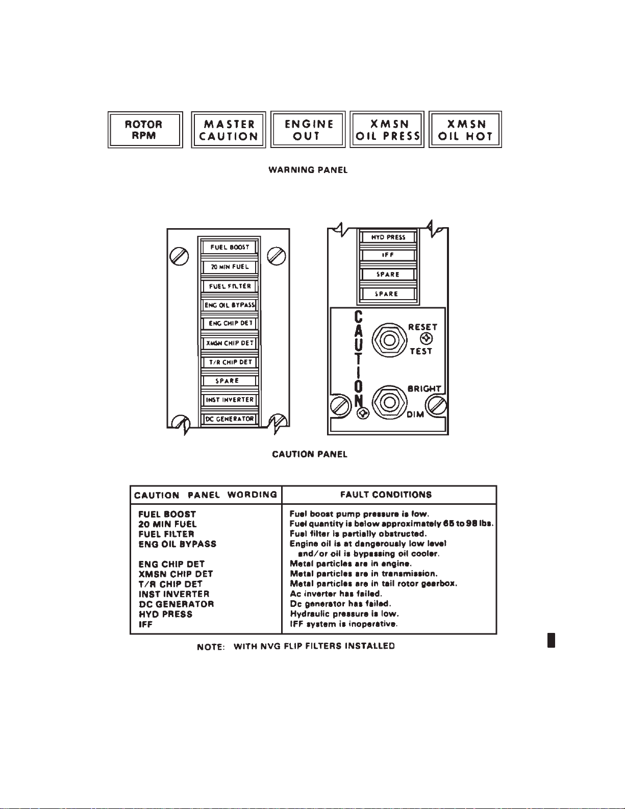
TM 55-1520-228-10
Figure 2-19. Warning and Caution Panels
Change 11 2-47
Page 96

TM 55-1520-228-10
switch (figure 2-19) controls the brightness of the caution panel lights and the MASTER CAUTION light. The
INST L TS switch must be moved from the DIM position
before the caution panel lights can be dimmed. The
system is so designed that after each initial application
of power, the lamps will illuminate in the bright condition.
c. Warning System. The warning system consists
of five individually illuminated warning light segments
mounted in the MASTER CAUTION and warning light
panel (figure 2-19) on the instrument panel. The purpose of this system is to provide visual indication for day
or night operation that any of the five conditions or combinations thereof has occurred. Each fault condition as
it occurs is indicated by a steady illumination of the lettering on the particular segment. In addition, an audio
signal sounds when the ENGINE OUT or ROTOR RPM
segment is illuminated and the collective pitch is not in
the full down position. The warning indicator segment
SECTION XIV. SERVICING, PARKING, AND MOORING
2-73. SERVICING.
a. Servicing Diagram. Refer to figure 2-20 and fig-
ure 2-21.
b. Fuels, Oils, Fluids, Specifications, and Capacities. Refer to table 2-1.
remains illuminated until the fault condition is corrected.
ENGINE OUT Engine N1 speed below
55 $ 3%
XMSN OIL PRESS Transmission oil pressure
below 30 $ 2 psi
XMSN OIL HOT Transmission above
110_C
ROTOR RPM Rotor rpm below 95% $
1.4%
MASTER CAUTION Fault condition in caution
panel
The WARNING L TS TEST switch (figure 2-13 and figure
2-14) is pressed to check for illumination of all the warning lights.
b. JP-5 and JP-8. These fuels contain icing inhibitors blended at the refinery. Jet A and Jet A1 are JP-5
type fuels without icing inhibitors.
c. Emergency Fuel. Aviation gasolines (MIL-G-
(5572) without Tricresyl Phosphate (TCP) are desig-
nated as the emergency fuels to be used in this air-
craft.
2-74. APPROVED FUELS, OILS, AND
FLUIDS.
a. Fuels. Refer to table 2-2.
b. Oils. Refer to table 2-3.
c. Fluids. Refer to table 2-4.
2-75. FUEL TYPES. See table 2-2.
a. JP-4. This fuel contains icing inhibitor lended at
the refinery. Commercial Jet B is a JP-4 type fuel; its
mixture may or may not contain icing inhibitors.
2-48 Change 11
2-76. USE OF FUELS.
a. JP-4. There is no special limitation on the use of
JP-4 fuel, but limitations are imposed when fuels other
than JP-4 are used.
b. JP-5, JP-8, Jet A, and Jet A1. These fuels may
be added to JP-4 and to each other in any quantities.
c. Emergency Fuels. Aviation gasoline may also
be added to turbine engine fuels in any quantity. Fuel
mixtures containing any amount of Aviation Gasoline
must be recorded in the Remark Section of DA Form
2408-13-1 as an emergency fuel, noting the type of fuel,
additives, and duration of operation. The 6 hour total
engine operation limitation applies.
d. Refer to fuel operation limits, Chapter 5, when
fuels other than JP-4 are used.
Page 97
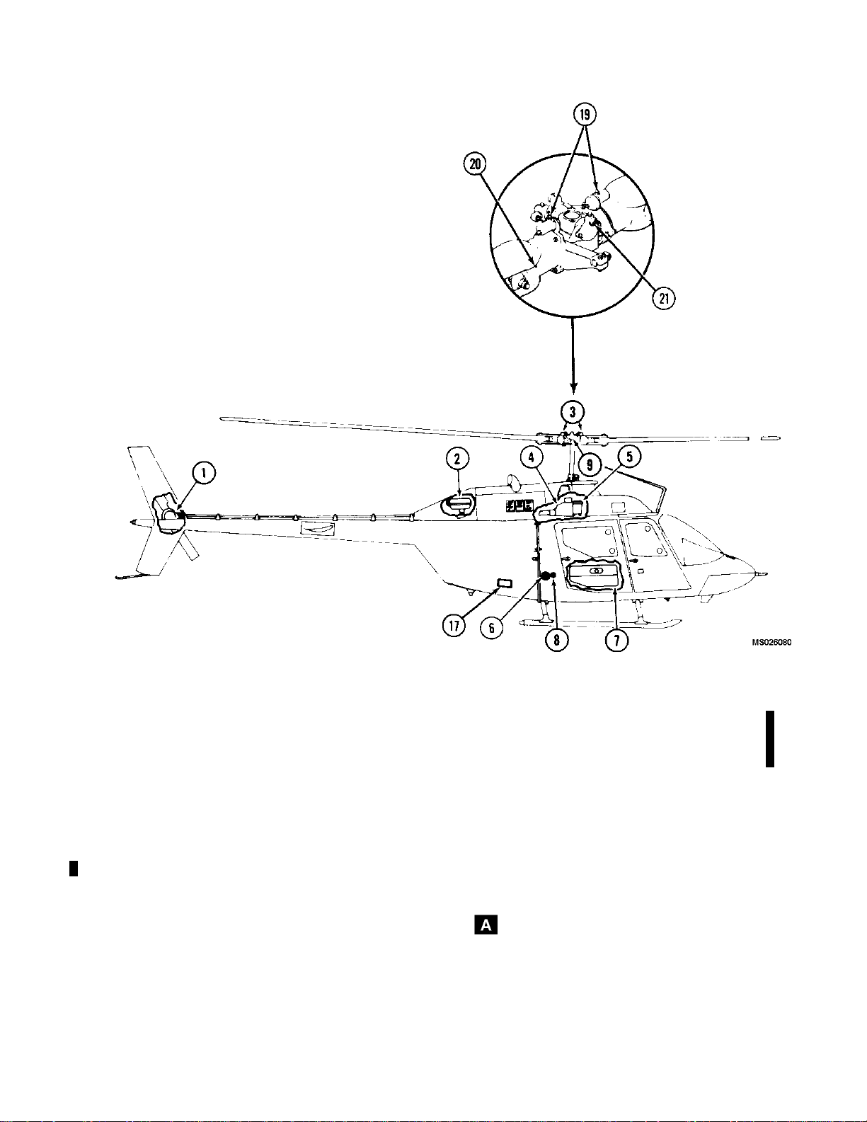
TM 55-1520-228-10
1.
2.
3.
4. Transmission 15.
5.
6. Fuel Tank Filler 17. External Power Receptacle
7.
8.
9. Pillow Bloc
10.
11.
Figure2-20. Servicing Diagram (Sheet 1of 2)
Tail Rotor Gearbox
Engine Oil Tank
Grip Reservoirs
Hydraulic Reservoir 16. Hydraulic Filler Cap
Auxiliary Fuel Cell
Static Ground Receptacle
k Reservoirs
Transmission Oil Filler Cap
Transmission Oil Filter
21.
12. Deleted
13. Deleted
14.
18.
19.
20.
Tail Rotor Gearbox Filler Cap
Engine Oil Filler Cap
Fuel Cell Sump Drain Valve
Relief Valve
Fitting Lubrication (Grease Lubrication)
Fitting Lubrication (Grease Lubrication)
Change 14 2-49
Page 98
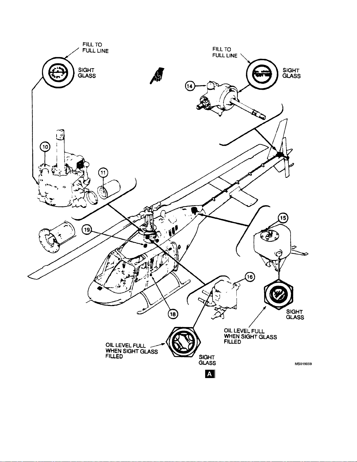
TM 55-1520-228-10
2-50 Change 11
Figure 2-20. Servicing Diagram (Sheet 2of 2)
Page 99
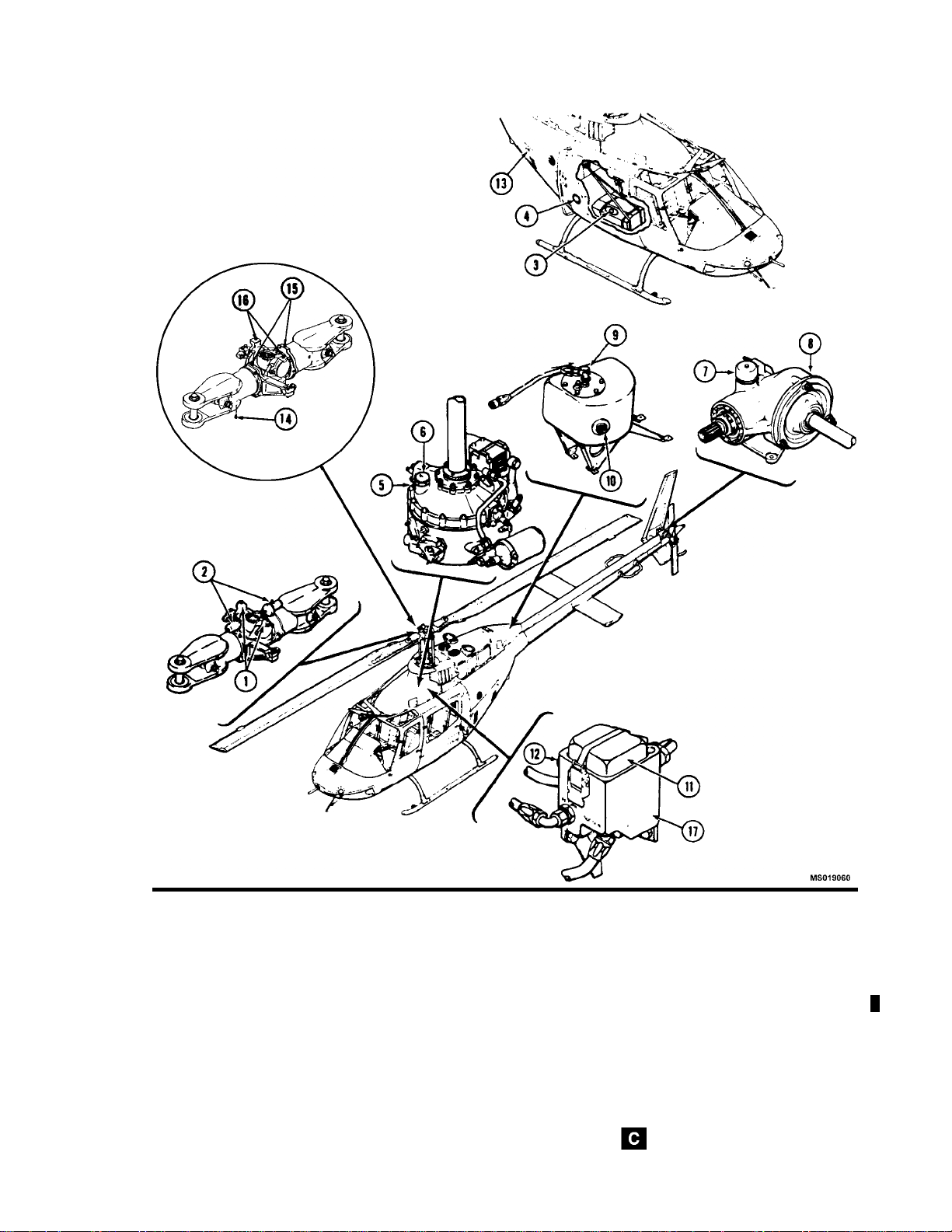
TM 55-1520-228-10
Pillow Block Reservoir Grease Fittings
1.
Grip Reservoir
2.
Auxiliary Fuel Filler Cap
3.
Closed Circuit Refueling Receiver
4.
Transmission Sight Glass
5.
Transmission Filler Cap
6.
Tail Rotor Gearbox Filler Cap
7.
Tail Rotor Gearbox Sight Glass
8.
Engine Oil Filler Cap
9.
Figure 2-21. Servicing Diagram
10.
Engine Oil Ta
10.1. Deleted
11.
Hydraulic
12.
Hydrauli
13.
Static Ground Receptacle
14.
Fitting
15.
16.
17. Hydraulic Reservoir
Valve (Grease Lubricated Hub)
Relief
ng Lubrication (Grease Lubricated Hub)
Fitti
nk Sight Glass
Filler Cap
c Sight Glass
Lubrication (Grease Lubricated Hub)
Change 14 2-51
Page 100
TM 55-1520-228-10
Table 2-1. Fuels, Oils, Fluids, Specifications, and Capacities
SYSTEM SPECIFICATION CAPACITY
Fuel
(Note 1)
Fuel
(Auxiliary Fuel Cell)
(Note 1)
Engine Oil
(Note 2)
MIL-T-5624 (JP-4)
MIL-T-5624 (JP-5)
MIL-T-83133 (JP-8)
MIL-G-5572 (without TCP) Emergency Fuel
MIL-T-5624 (JP-4)
MIL-T-5624 (JP-5)
MIL-T-83133 (JP-8)
MIL-G-5572 (without TCP) Emergency Fuel
If DOD-L-85734 oil is added to any turbine engine or engine
lubricated gearboxes, the engine/gearbox should be drained
and flushed with proper lubricant when it becomes available.
*Lubrication oil made to MIL-L-7808 by Shell Oil Company under their part number 307, qualification number 7D-1, shall not
be used in OH-58A/C engine or helicopter systems. It contains
additives which are h armful to seals in the systems.
*MIL-L-7808 NATO Code is 0-148
For use in ambient temperatures below minus 32°C/25° F
MIL-L-23699 NATO Code is 0-156
For use in ambient temperatures above minus 32°C/25° F
71.5 U.S. Gal
(70.3 usable)
23.9 U.S. Gal
11.2 U.S. Pt
Transmission Oil
(Note 2)
2-52 Change 7
*Lubrication oil made to MIL-L-7808 by S
der their part number 307, qualification number 7D-1, shall not
be used in OH-58A/C engine or helicopter systems. It contains
additives which are harmful to seals i
*MIL-L-7808 NATO Code is 0-148
For use in ambient temperatures below minus 32°C/25° F MIL-L-23699
NATO Code is 0-156
For use in ambient temperatures above minus 32°C/25° F
DOD-L-85734 for use in ambient temperatures above -40°C/40°F
hell Oil Company un-
n the systems.
4.0 U.S. Qts.
 Loading...