

HDT Camfire MV60-EU, Camfire MV60S-EU, Camfire MV60T-EU Operation And Maintenance Manual
`
HDT –Tactical Systems Business Unit
30525 Aurora Rd
Solon, Ohio 44139-2795
Tech Support: (800) 684-6111
www.hdtglobal.com
MV60-EU Series Heaters, 220 VAC, 50-60 Hz
SHELTER HEATER
60,000 BTU Multi-fuel Shelter Heater
Operation and Maintenance Manual
MANUAL PART NUMBER: 53858
REVISION 3 – 26APRIL2011

THIS PAGE INTENTIONALLY LEFT BLANK
Operation and Maintenance Manual
Warning Summary
IMPORTANT
Be sure to read and understand this operation and maintenance manual before starting or servicing this
heater.
WARNING!
FIRE, EXPLOSION, CARBON MONOXIDE POISONING
Improper use of this heater can result in serious bodily injury due to hazards of fire and explosion, carbon
monoxide poisoning, burn and electrical shock. Do not adjust the pump pressure higher then the
recommended amount. Failure to do so can result in higher then normal heat exchanger temperatures,
which can cause the heat exchanger to fail allowing dangerous Carbon Monoxide gas to enter the shelter.
Failure to follow these instructions could cause serious injury or death.
WARNING!
FIRE, EXPLOSION
Use only Kerosene, Diesel or Number 1 Fuel Oil, or JP8 can be used for extreme cold conditions. Never
burn gasoline, naphtha, paint thinners, alcohol or other volatile fuels. Fill fuel tank or move heater only
when heater is shut off.
WARNING!
FIRE, EXPLOSION
Use only in areas free of flammable vapor or high dust content. Never use heater where gasoline, paint
thinner or other highly flammable vapors are present.
WARNING!
EXPLOSION
Fully drain and ventilate fuel tank before transporting.
3
Operation and Maintenance Manual
WARNING!
ROTATING MACHINERY
When used with thermostat, heater may start at any time. Do not open access door while heater is
running or plugged in. Remove all power prior to service.
WARNING!
SHOCK HAZARD
Use only with electrical voltage and frequency specified on model plate. Do not perform any service with
heater plugged in.
WARNING!
HIGH VOLTAGE
The ignition transformer develops 10,000 volts. Serious injury or death may occur if personnel come in
contact with high voltage lead.
WARNING!
FIRE, EXPLOSION
Do not operate heater without output duct, P/N CAH-1015, properly installed. Ensure hot air outlet is at
least 1.5 meters from combustible materials. Ensure ducts (outlet and inlet) are free from obstructions and
sharp bends. ALWAYS REMOVE STORAGE PLUG CAH-126-1 BEFORE OPERATING HEATER.
WARNING!
HOT SURFACES
Parts of the heater become very hot when operating and immediately after operating. The exhaust can
reach temperatures in excess of 1000 degrees Fahrenheit. Severe burns may occur if the heater is not
allowed to cool down properly before servicing.
4

Operation and Maintenance Manual
WARNING!
CARBON MONOXIDE POISONING
The heat exchanger must be inspected annually by qualified service personnel for leaks which could
allow dangerous carbon monoxide gas to enter the shelter. Failure to due so, could cause severe
injury or death.
5

Operation and Maintenance Manual
Table of Contents
Operation and Maintenance Manual ............................................................................................................. 1
1. System Overview, Description and Principles of Operation ............................................................... 10
1.1 System Overview .......................................................................................................................... 10
1.2 Description of Major Components ................................................................................................ 11
1.3 Controls and Indicators ................................................................................................................. 14
1.4 WARNING Labels and Data Plates .............................................................................................. 16
1.5 CAMFIRE Heater Specifications .................................................................................................. 19
1.6 Principles of Operation ................................................................................................................. 20
2. Setup and Operation of the CAMFIRE Heater ................................................................................. 25
2.1 Preparing the Heater for Operation .............................................................................................. 25
2.1.1 Unpacking .............................................................................................................................. 25
2.1.2 Installing the Exhaust Stack Extension ................................................................................. 25
2.1.3 Removing the Accessories .................................................................................................... 26
2.2 Siting Considerations .................................................................................................................... 26
2.3 Setup ............................................................................................................................................ 27
2.3.1 Attaching the Flexible Ducts .................................................................................................. 27
2.4 Before Operation Preventative Maintenance Checks and Services (PMCS)............................... 30
2.5 Fueling .......................................................................................................................................... 30
2.5.1 Fueling the Internal Tank (MV60S-EU, MV60T-EU) ............................................................. 30
2.5.2 Connecting and operating the Remote Room Thermostat ................................................... 31
2.5.3 Connecting the Power Cable ................................................................................................. 32
2.6 Final Checks Before Operation .................................................................................................... 33
2.7 Starting and Operating the Heater ................................................................................................ 33
2.7.1 Starting the Heater ................................................................................................................ 33
2.8 Refueling During Operation .......................................................................................................... 34
2.9 Shutting Down the Heater ............................................................................................................ 34
2.10 Preparing for Movement or Storage.......................................................................................... 34
2.10.1 Preparing for Movement ........................................................................................................ 34
2.10.2 Preparing the Heater for Storage .......................................................................................... 35
3. CAMFIRE Troubleshooting .................................................................................................................. 38
3.1 Introduction ................................................................................................................................... 38
3.2 Operator Level Troubleshooting ................................................................................................... 38
3.3 Safety Control Operation and Diagnostics ................................................................................... 38
3.3.1 Operator Level Malfunction Symptom Index ......................................................................... 39
3.3.2 Examining the Heater ............................................................................................................ 39
3.3.3 Test Firing the Heater ............................................................................................................ 40
3.3.4 Operator Level Troubleshooting Procedures ........................................................................ 40
3.4 Maintainer Level Troubleshooting ................................................................................................ 45
3.4.1 Test Firing .............................................................................................................................. 45
3.4.2 Maintainer Level Safety Control Operation and Diagnostics ................................................ 45
3.4.3 Maintainer Level Malfunction Symptom Index ...................................................................... 46
3.4.4 Maintainer Level Troubleshooting Procedures ...................................................................... 47
4. CAMFIRE Maintenance ....................................................................................................................... 54
4.1 Introduction ................................................................................................................................... 54
4.2 Preventive Maintenance Checks and Services ............................................................................ 54
4.2.1 Introduction ............................................................................................................................ 54
4.2.2 Removing Upper Shell .......................................................................................................... 56
4.2.3 Preventive Maintenance Checks and Services ..................................................................... 57
4.3 Special Tools, Equipment and Supplies ....................................................................................... 61
6

Operation and Maintenance Manual
4.4 System Maintenance Procedures ................................................................................................. 61
4.4.1 General .................................................................................................................................. 61
4.4.2 Remote Room Thermostat (Inspect/Test) ............................................................................. 62
4.4.3 Ignition Transformer (Inspect/Test) ....................................................................................... 63
4.4.4 Checking Motor Starting Circuits (Test) ................................................................................ 65
4.4.5 Fan Service ........................................................................................................................... 67
4.4.6 Sediment strainer Service ..................................................................................................... 68
4.4.7 Burner Head Service (Clean) ................................................................................................ 69
4.4.8 Air Pump Repair (Inspect, Test, Repair) ............................................................................... 73
4.4.9 Safety Control Circuit Testing (Test, Clean) .......................................................................... 81
4.4.10 Photocell (Test) ..................................................................................................................... 85
5. Illustrated Parts Listing......................................................................................................................... 88
6. Schematics and Wiring Diagrams ...................................................................................................... 106
7. Alphabetical Index .............................................................................................................................. 108
7

Operation and Maintenance Manual
Table of Figures
Figure 1-1. CAMFIRE Control Panel ........................................................................................................... 14
Figure 1-2. Remote Room Thermostat ....................................................................................................... 15
Figure 1-3. System Operational Diagram (simplified for clarity) ................................................................. 21
Figure 4-1. Camfire Maintenance Locations ............................................................................................... 56
Figure 4-2. Wiring Diagram ......................................................................................................................... 66
Figure 4-3. Location of Fan on Shaft .......................................................................................................... 67
Figure 4-4. Checking clearance of air pump rotor....................................................................................... 78
Figure 5-1. MV60-EU Labels and Accessories ........................................................................................... 88
Figure 5-2. MV60-EU FULL ASSEMBLY .................................................................................................... 90
Figure 5-3. COMBUSTION CHAMBER ASSEMBLY .................................................................................. 92
Figure 5-4. BURNER HEAD ASSEMBLY 53649 ........................................................................................ 94
Figure 5-5. MV60 CONTROL BOX-FUEL BRACKET ASSEMBLY ............................................................ 96
Figure 5-6B. CONTROL BOX ASSEMBLY ................................................................................................. 98
Figure 5-7. MOTOR/PUMP/BRACKET ASSEMBLY (53745) ................................................................... 100
Figure 5-8. MOTOR AND PUMP ASSEMBLY(53485) ............................................................................. 102
Figure 6-1. Camfire Heater Wiring Diagram ............................................................................................. 106
Figure 6-2. Camfire (MV60) Fuel Schematic ............................................................................................ 107
Table of Tables
Table 1-1. CAMFIRE Heater Warning Labels and Data Plates ................................................................. 16
Table 1-2. Camfire Heater Specifications ................................................................................................... 19
Table 2-1. Flexible Duct Usage vs. Outside Temperature .......................................................................... 27
Table 2-2. Extension Cord Size Requirements ........................................................................................... 32
Table 3-1. Operator Level Malfunction Symptom Index ............................................................................. 39
Table 3-2. Operator Level Troubleshooting Procedure .............................................................................. 40
Table 3-3. Maintainer Level Malfunction Symptom Index ........................................................................... 46
Table 3-4. Maintainer Level Troubleshooting Procedures .......................................................................... 47
Table 4-1. Camfire Heater Preventive Maintenance Checks and Services ................................................ 57
Table 5-1. MV60 Labels and Accessories .................................................................................................. 89
Table 5-2. Combustion Chamber Assembly ............................................................................................... 93
Table 5-3. Burner Head Assembly 53649 ................................................................................................... 95
Table 5-4. Control Box-Fuel Bracket Assembly .......................................................................................... 97
Table 5-5. Control Box Assembly ............................................................................................................... 99
Table 5-6. Motor/Pump/Bracket Assembly ............................................................................................... 101
Table 5-7. Motor and Pump Assembly P/N 53485.................................................................................... 103
8

Chapter 1
System Overview,
Description and
Operation and Maintenance Manual
Principles of Operation
9

Operation and Maintenance Manual
1. System Overview, Description and
Principles of Operation
1.1 System Overview
The CAMFIRE Heaters are portable, clean-air space heaters that rely on an external input of 220 VAC,
50/60 Hz, single phase power.
The heart of the heater is a heat exchanger that is supplied with air from a fan driven by a 1/4 horsepower
motor. Part of the air from the fan enters the combustion chamber where it mixes with the atomized fuel to
become a combustible mixture. The exhaust gases circulate within the heat exchanger; warming its inner
surfaces, then escape from the heater through a flue pipe adapted to the top of the heater.
The remaining air from the fan passes over and around the combustion chamber and through the heat
exchanger where it is heated, and emerges from the heater as a powerful stream of heated clean air.
The heater is provided with duct connectors at the outlet and inlet ends, allowing use either in a 100%
fresh air mode or 100% recirculation air mode.
The fuel system consists of an air pump mounted on one end of the motor shaft that forces air through
the nozzle. The moving air in the nozzle lifts the fuel from the tank by siphon action and carries it into the
combustion chamber.
Filters protect the fuel system prior to the fuel entering into the spray nozzle. The electrical control system
is protected by a push button type circuit breaker.
A safety control unit, connected to a photoelectric cell, shuts down the heater if a flame is not detected in
the combustion chamber after start up. It also has two diagnostic LEDs to help troubleshoot problems. A
”Duct Over-Heat” switch is installed as a safety measure. In the event that the outlet duct becomes
blocked, the switch will shut the heater down.
A thermostat accessory, which plugs into the electrical system of the heater, may be set to any desired
temperature. When the temperature of the surrounding air reaches the pre-set temperature, the
thermostat contacts open and cause the heater to shut down. When the air cools, the thermostat contacts
close and the heater recycles.
The heater is designed for hard use in rough environments resulting in a minimum of down time for repair
and maintenance. It is protected by roll bars to prevent damage by upset or rollover and shrouded to
protect the working portion of the heater against falling objects.
The heater can be fitted with added accessories such as wheels, skis or toboggan. A spares kit is also
available that includes filters, spark plug, and fuel regulating components.
10
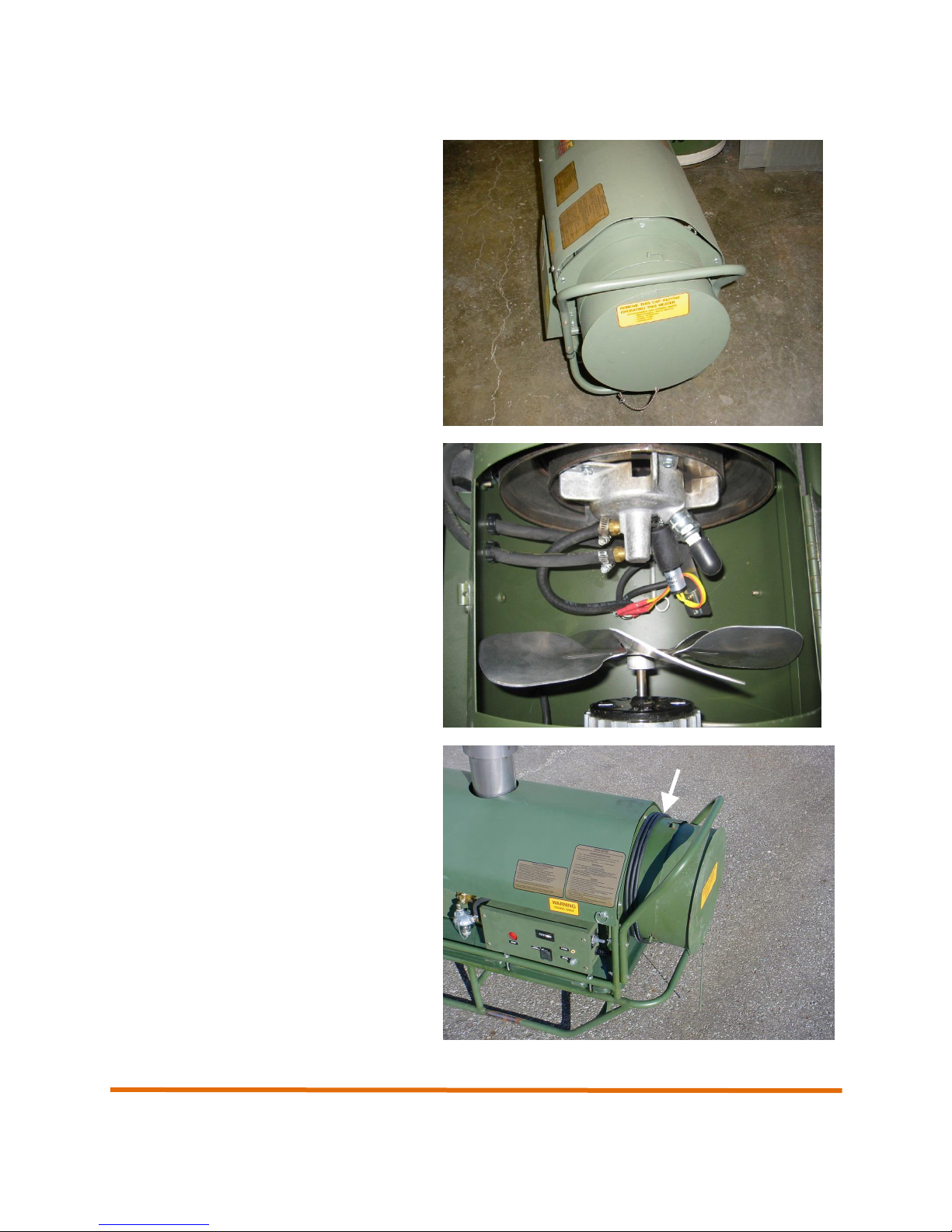
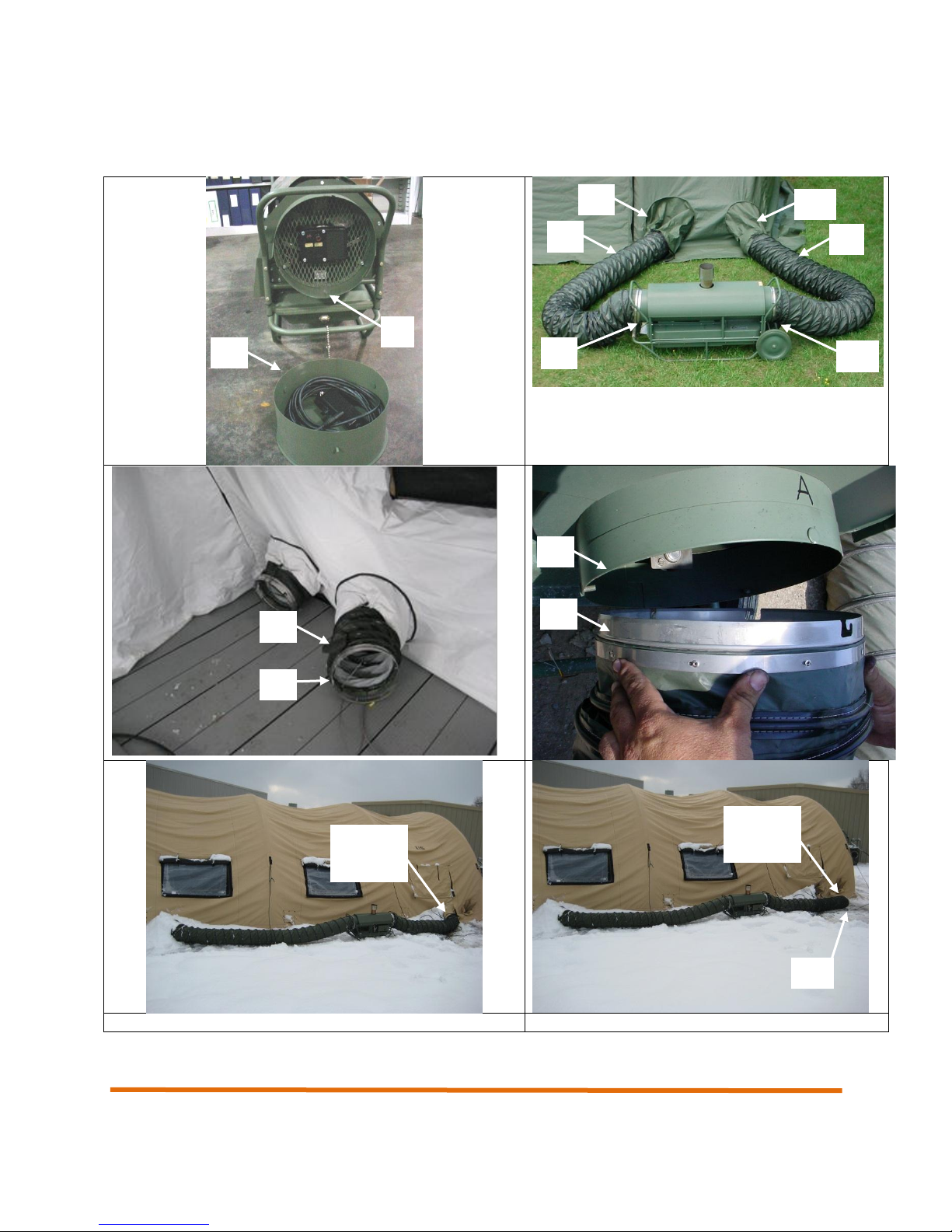
1.2 Description of Major Components
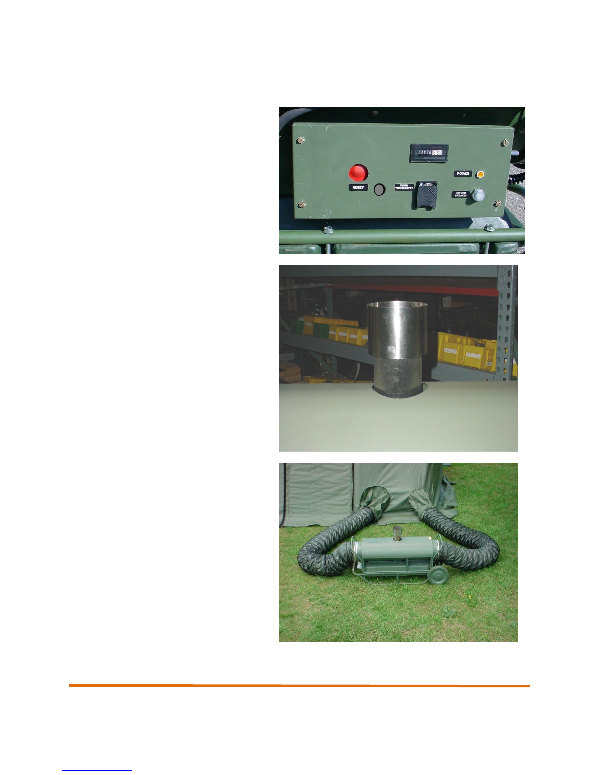
Control Panel – Contains all operation
controls for heater including power input
connector, optional remote room thermostat
connector, and hour meter.
Exhaust Stack Extension– The exhaust
stack extension is installed in the exhaust
outlet on the top of the heater and acts to
direct the combustion gases away from the
heater.
An internal screen in the exhaust stack
extension acts as a spark arrester.
Inlet and outlet ducts – 15 foot flexible
ducts connect to the shelter duct tunnels and
circulate heated and unheated air through the
shelter.
Operation and Maintenance Manual
11
Operation and Maintenance Manual
End plug – Installs into the inlet end of the
heater and is used to house accessory items
such as the remote room thermostat.
Burner assembly – The burner assembly is
where all combustion occurs within the
Camfire heater. Atomized fuel is mixed with
air and ignited by the spark plug to create the
heat circulated through the shelter.
Power cable – A 6-foot long AC power cable
that connects the heater with a 220` VAC
power source. The power cable is wrapped
around the inlet duct adapter.
12
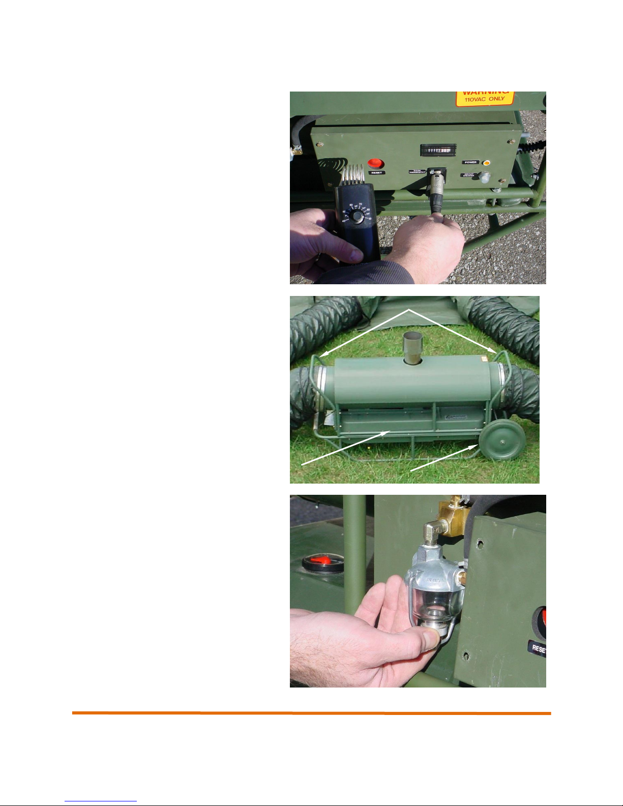
Operation and Maintenance Manual
Remote Room Thermostat – Permits
automatic temperature control inside a
shelter. The remote room thermostat hangs
inside the shelter and monitors the shelter
temperature. If the shelter temperature falls
below the set point on the thermostat, the
heater will start and begin supplying heat
until the set point is reached.
Roll bars, handles, and local transport
wheels* – Handles are located at either end
of the heater and permit the heater to easily
be moved into position. Roll bars are located
around the heater and act to protect the
heater from damage. Local transport wheels
(optional accessory) permit the heater to be
rolled into position.
* Local transport wheels are an optional accessory.
Sediment strainer assembly. Allows for
visual inspection of fuel for dirt and water. Is
able to be easily removed and cleaned.
13
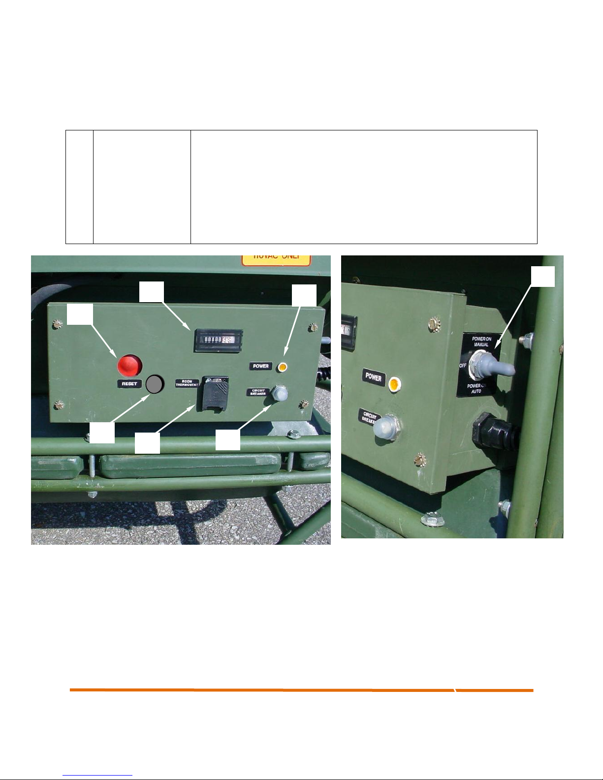
No.
Control
Description
1
Reset
Resets the heater in the event a problem shuts the heater down or a fault
condition occurs
2
Power ON AUTO/
ON MANUAL
Turns heater power on and selects AUTO or MANUAL heat mode
3
Pilot Light
Indicates that power is supplied to the heater.
4
Thermostat Jack
Permits the connection of the remote thermostat assembly.
5
Hour meter
Displays the total number of operating hours for the heater.
6
Circuit Breaker
Protects the heater against circuit overload
7
View Port
Allows the user to view the diagnostic LEDs, for troubleshooting and repair
1
2
3
4
5
6
7
1.3 Controls and Indicators
Operation and Maintenance Manual
Figure 1-1. CAMFIRE Control Panel
14
Operation and Maintenance Manual
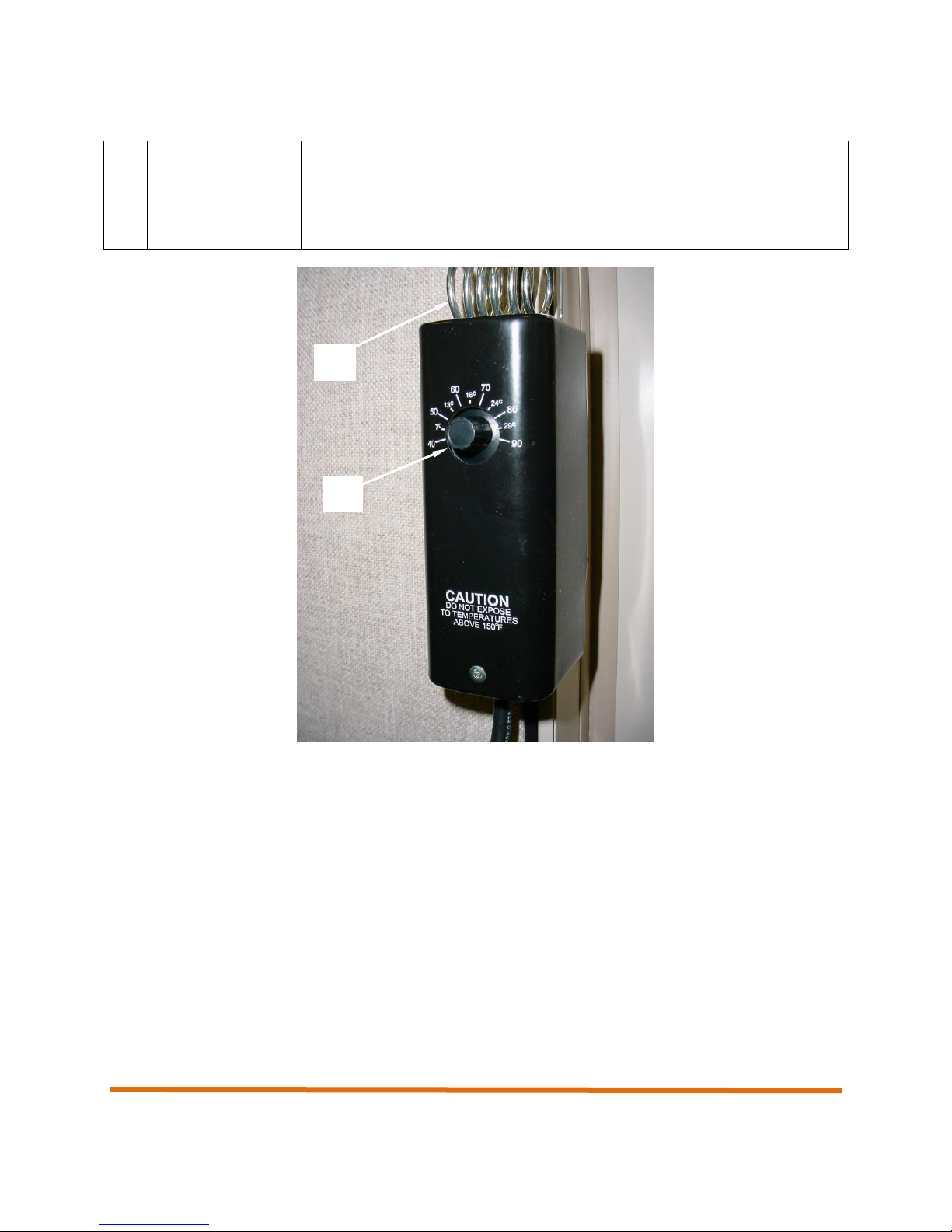
No.
Control
Description
1
Variable
Temperature
Control
Placed inside the shelter being heated, permits the operator to set the
desired temperature of the shelter.
2
Temperature
Sensing Coil
Located on the top of the remote room thermostat, monitors the temperature
of the shelter.
1
2
Figure 1-2. Remote Room Thermostat
15
Operation and Maintenance Manual
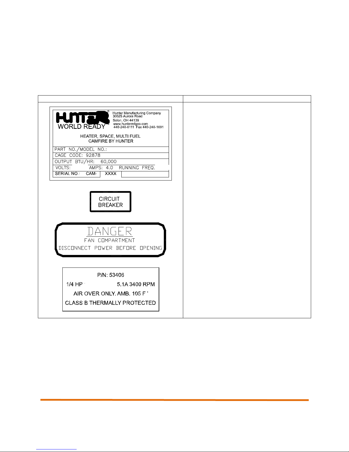
WARNING Label or Data Plate
Location/Description
Located on the side of the heater, the data plate
provides pertinent data including Model Number
and Serial Number
Located on the control panel, identifies the
circuit breaker. See section on controls and
indicators.
Located near the fan compartment, warns user
of electrical shock potential inside fan
compartment.
Located on fan assembly, label identifies part
number and performance specs of fan.
1.4 WARNING Labels and Data Plates
The following section contains a description of all WARNING labels and data plates associated with the
Camfire Heater.
Table 1-1. CAMFIRE Heater Warning Labels and Data Plates
16
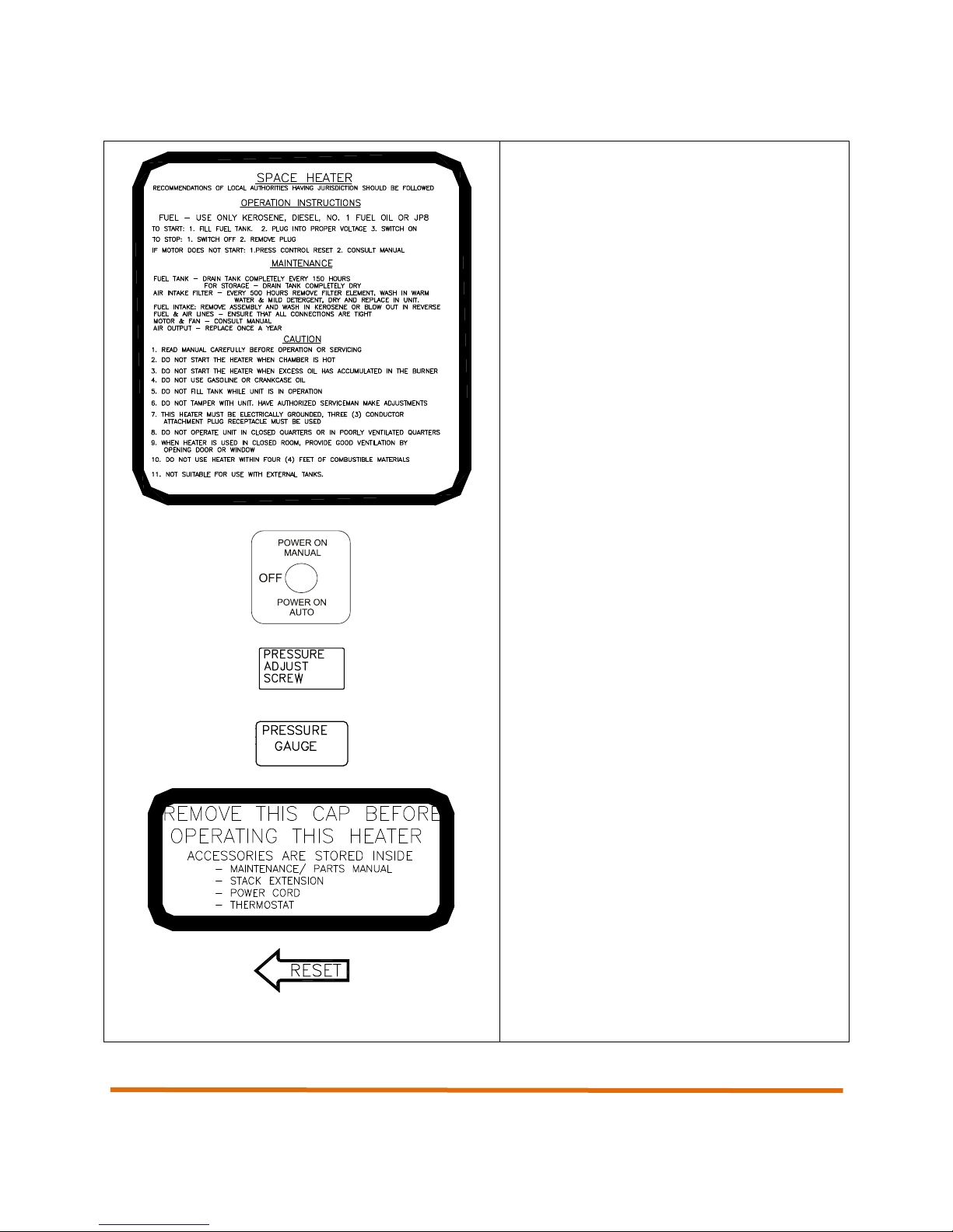
Operation and Maintenance Manual
Located on side of heater, label lists the
operating procedures for the heater in
abbreviated form.
Located on the control panel, identifies power
switch.
Located inside heater near air pump, identifies
pressure adjustment screw.
Located inside heater near burner assembly,
identifies pressure gauge.
Located on end plug at end of heater, identifies
the fact that the cap must be removed before
operation. Also informs user of accessories
stored inside end plug.
Located on control panel, identifies Reset
switch.
17
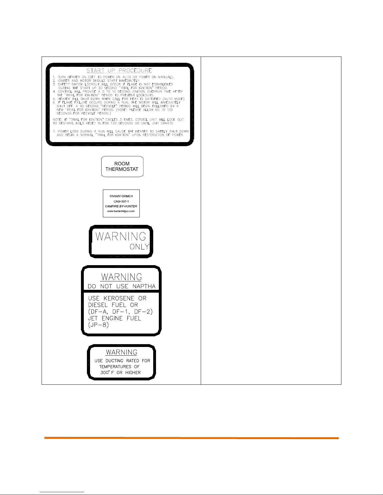
Operation and Maintenance Manual
Located on side of heater, details heater startup procedures.
Located on control panel, identifies remote
ROOM THERMOSTAT.
Parts ID tag located on the ignition transformer.
Located on control panel, alerts user that only
220VAC power should be used.
Located near fuel filler cap on side of heater,
warns user against the use of naptha and
identifies all approved fuels.
Located near duct connections at end of heater.
Warns user that only approved flexible ducts
rated for temperatures of 300 degrees F or
higher can be used.
220 VAC
18

MV60S-EU, MV60T-EU,
Input Heat Rating
BTU/Hour
90,000
Output Ratings
Clean-air Output, BTU/Hour
60,000
Volume, CFM (Approximate)
600
Other Ratings
Current, starting
3.5 AMPS
Current, running
2.2 AMPS
Voltage
220 VAC
Frequency
50/60 Cycles
Fan/Pump Motor
1/4 HP
Air Pump Pressure
5.0 PSI
Fuel Nozzle
Meter Size
0.65 GPH
Spray Angle
80 DEGREES
Fuel
Kerosene, DF1, DF2,
Fuel Oil, JP8 Only
Tank Capacity
8.5 GAL
Flexible Ducts (2)
12 inch diameter
15 ft Length
Dimensions (Without Stack
Extension)
W15” L46” H25”
Weight (Without Fuel)
105 LBS
1.5 CAMFIRE Heater Specifications
Table 1-2. Camfire Heater Specifications
Operation and Maintenance Manual
19

Operation and Maintenance Manual
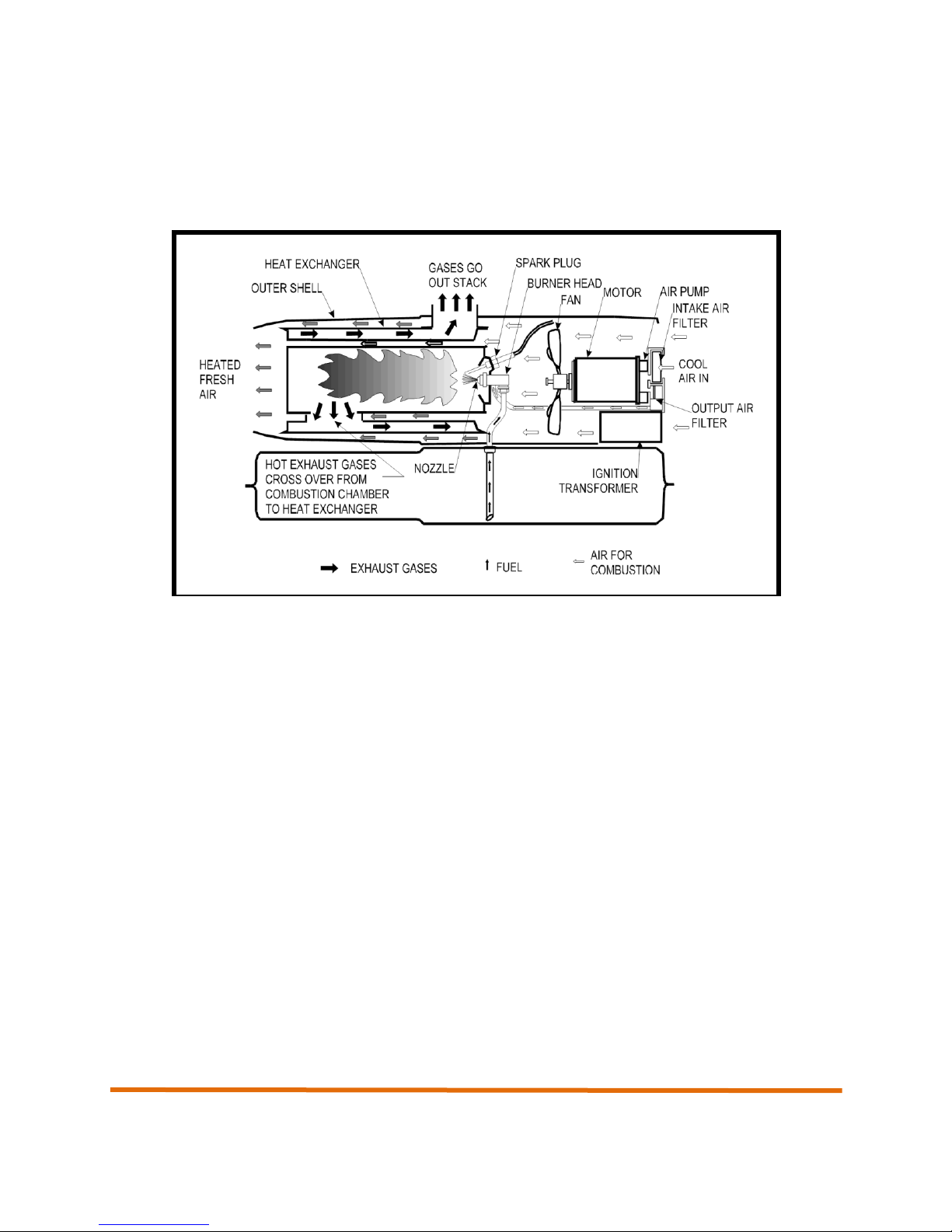
1.6 Principles of Operation
Fuel System
An air pump on one end of the motor shaft forces the air through the nozzle. The moving air lifts fuel from
the tank or from the remote fuel source ( AND version) by a siphon action and carries it into the
combustion chamber in a fine spray.
Air System
The air system is divided into two parts, both are supplied with air from a fan that is attached to the other
end of the motor.
Part of the air from the fan enters the combustion chamber where it mixes with the atomized fuel to
become a combustible mixture, and also mixes with the burning gases to complete the process of
combustion.
The exhaust gases from the combustion chamber circulate within the inner surfaces of the heat
exchanger. They are then ducted out of the heater through the stack adapter on its’ top and out of the
heater space through a flue pipe.
The rest of the air from the fan passes over and around the combustion chamber and through the heat
exchanger where it is heated and emerges from the front of the heater as a powerful stream of heated
fresh air, without being mixed with the products of combustion.
Ignition System
The ignition system consists of a transformer and spark plug. The transformer increases the input voltage
to a very high potential that causes an arc to be drawn between the electrodes of the spark plug. The arc
is used to ignite the fuel and air mixture within the combustion chamber.
Control System
The safety control circuit consists of a duct over heat switch, a light sensitive photocell, and a safety
control. The safety control will trip if the heater fails to ignite or the flame goes out, thereby causing the
heater to shut down. The safety control has two diagnostic LEDs which can be seen through a hole in the
front of the control panel.
The photocell is used to sense the presence of light due to the flame inside the combustion chamber. It
varies its’ electrical resistance in relation to light rays. When under the influence of light, the cell has very
low resistance. The resistance is high when little or no light strikes the light sensitive surface. The flame
sensor’s function is to control the safety control.
A ”duct over-heat” switch is located at the outlet end of the heater. This switch will shut down the heater if
the duct temperature exceeds approximately 275 deg. F.
A thermostat accessory, Part No. CAH-134-1, may be incorporated into the electrical circuit of the heater.
The thermostat can be set to any desired temperature between 35 deg. F and 95 degrees F. When the
20
Operation and Maintenance Manual
temperature of the surrounding air reaches the pre-set temperature, the thermostat contacts open and
cause the heater to shut down. When the air cools, the thermostat contacts close and the heater recycles.
A ”duct over-heat” switch is located at the outlet end of the heater. This switch will shut down the heater if
the duct temperature exceeds approximately 275 degrees F.
Figure 1-3. System Operational Diagram (simplified for clarity)
21

Operation and Maintenance Manual
22

Operation and Maintenance Manual
Chapter 2
Setup and Operation of the
CAMFIRE Heater
23

Operation and Maintenance Manual
24
Operation and Maintenance Manual
2. Setup and Operation of the CAMFIRE Heater
2.1 Preparing the Heater for Operation
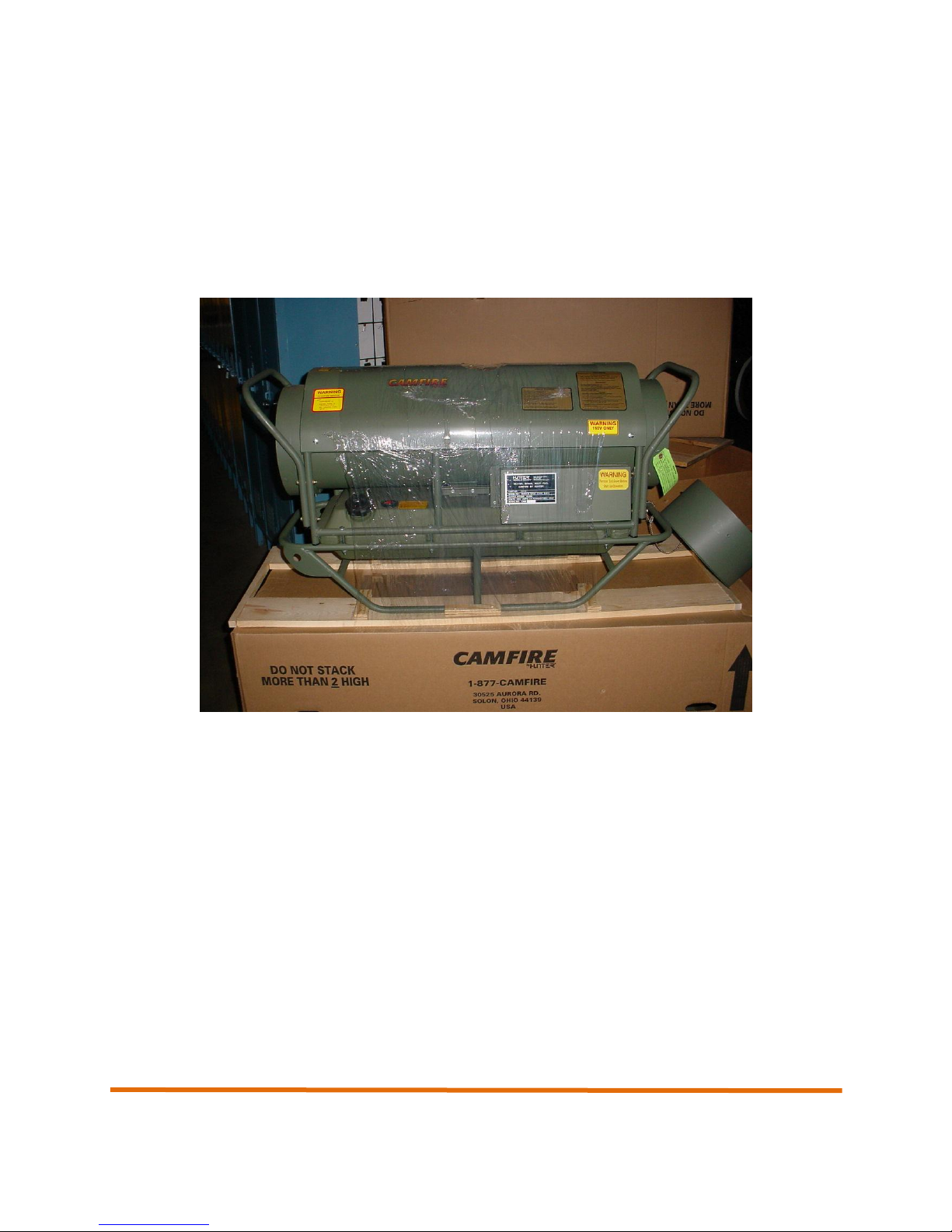
2.1.1 Unpacking
The Camfire heater is shipped mounted to a shipping pallet and wrapped in a plastic wrap material. When
unpacking the heater, remove all protective material covering the heater and remove the unit from the
shipping pallet.
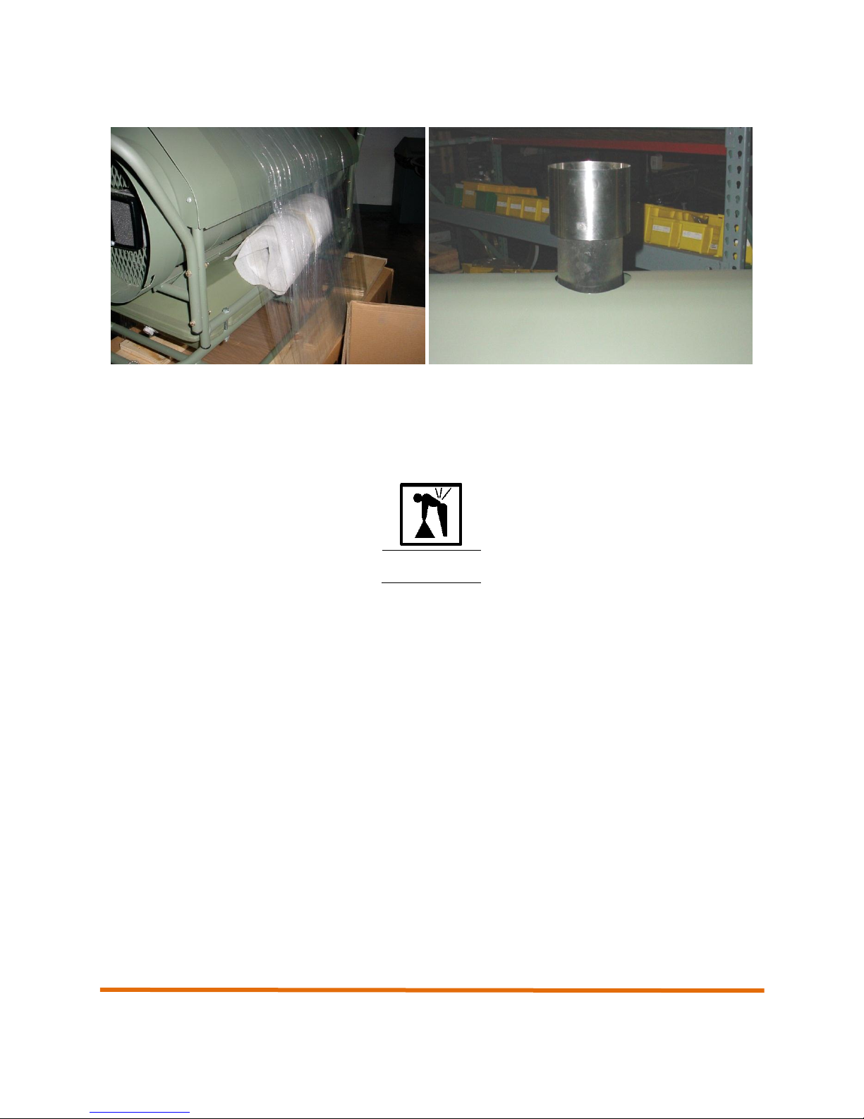
2.1.2 Installing the Exhaust Stack Extension
The exhaust stack extension is wrapped in foam and packaged to the side of the heater. Unwrap the
exhaust stack extension and install on the top of the heater by engaging the exhaust stack extension into
the exhaust port at the top of the heater. Push down and seat securely.
25
Operation and Maintenance Manual
WARNING
2.1.3 Removing the Accessories
Remove the end plug by pushing in and rotating counterclockwise to release from the J-slot. Pull the end
plug to disengage it from the heater and remove the remote room thermostat. Set the thermostat aside.
2.2 Siting Considerations
The CAMFIRE heater weighs approximately 105 pounds dry weight (48 kg). A fully fueled
heater weighs 165 pounds (74.8 kg). Two persons must carry the CAMFIRE heater when
lifting or lowering the unit. Be sure to lift with legs, not back, to prevent injury.
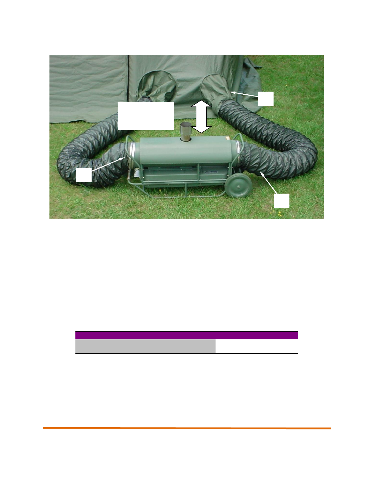
The CAMFIRE heater site location will be dictated by the location of the shelter since the heater inlet (1)
and outlet (2) ducts must be able to reach the shelter duct tunnels (3). (see photo next page)
The heater site must be as level as possible and free of combustible material (e.g. dried twigs, leaves.
etc.). If snow is present, it should be removed from the area immediately beneath and around the heater.
The site should be selected so that the heater will be positioned at least 2 feet (61 cm) from combustibles,
including the shelter wall.
26
Below 320F
Above 320F
Use Heated Air Outlet Duct Only
X
Use Air Inlet Duct and Heated Air Outlet Duct
X
Position heater
at least 2 feet
from shelter wall
1
2
3
Operation and Maintenance Manual
Positioning the Heater Outside Shelter. Place heater on the side of the shelter that has the shelter duct
tunnels. The heater should be a minimum of 2 feet (61 cm) from shelter walls. If possible, position the
heater so that the control panel faces away from the shelter wall. Position the heater so that the two
supplied 15-foot flexible ducts can be connected to the heater and the shelter duct tunnels.
2.3 Setup
2.3.1 Attaching the Flexible Ducts
General. Two air ducts, 15 feet in length and 12 inches in diameter, connect to the inlet and outlet ends
of the heater and move air from the interior of the shelter, through the heater, and back to the interior of
the shelter. In conditions where the outside ambient temperature is above freezing, only the heated air
supply duct is used. In this way, the heater draws unheated air from the outside. Operating the heater
without input ducting in warmer temperatures allows the heater to run cooler, thus preventing safety
overheat shutdown.
Table 2-1. Flexible Duct Usage vs. Outside Temperature
27
Operation and Maintenance Manual
WARNING
Installing the Air Supply and Return Ducts (re-circulation mode). To install the heated air return and
air supply ducts (NOTE: air return duct to be installed only if outside temperatures are below freezing),
remove end plug (1) from the heater duct adapter (2) on the air inlet end of the heater by pushing in and
rotating clockwise to disengage the protruding pins on the end plug from the J-slots in the heater duct
adapter. Remove the power cable stowed inside the end plug and set aside.
During heater operation, air leaving the heated air outlet of the heater and passing
through the heated air return duct may exceed 220°F (104°C). Make sure shelter
personnel are aware of burn hazards and equipment hazards presented by the heated air
exiting the heated air duct.
CAUTION
Wear gloves whiles handling ducts. There may be sharp metal edges or burrs that could
cut you.
NOTE: The heater ducts are outfitted with J-slot, twist lock bands on each end. They can only be
attached one way. Make sure to match up the ends before attaching to the shelter. Locate the heated air
supply duct (3). Make sure inside and outside of duct are free of damage, dirt, and obstructions prior to
attachment to the heater assembly. Insert the outlet end (4) of the duct into the shelter duct tunnel (5)
closest to the heated air outlet end (6) of the heater as indicated by the label “Heated Air Outlet” on the
upper housing assembly. Make sure about 12 inches of the outlet end (4) protrude into the shelter (7) so
that the air can be directed away from the inlet properly. Secure the shelter duct tunnel tie straps. Do not
secure the straps so tightly that the air flow within the duct is restricted. Attach the end of the duct with the
J-slot bracket (8) to the duct adapter (9) on the heated air outlet end (6) of the heater. Engage the J-slot
onto the protruding pins on the inside of the duct adapter and push in fully. While pushing the duct in,
rotate the duct counterclockwise until it locks in place.
IMPORTANT
If using the heater on a shelter with a plenum, move the plenum to the side so it does not
obstruct the airflow. DO NOT ATTACH THE HEATER TO THE SHELTER PLENUM. The
heater will do a much better job of heating by blowing the heat on the floor.
Insert the end of the duct without the J-slot mounting bracket into the shelter duct tunnel (14) closest to
the air inlet end (15) of the heater as indicated by the label “Air Inlet” on the upper housing assembly.
Secure the shelter duct tunnel tie straps (16). Do not secure the straps so tightly that the air flow within
the duct is restricted. Attach the end of the duct with the pins onto the J-slots (17) to the duct adapter (18)
on the air inlet end of the heater. Engage the protruding pins onto the J-slots on the duct adapter and
push in fully. While pushing the duct in, rotate the duct counterclockwise until it locks in place.
28
Operation and Maintenance Manual
Re-circulation mode
Outside air mode (see next section)
7
1 2 5
3
4
6
8
9
14 3 15
12
Duct
shelter
Duct
shelter
inside
outside
29
Operation and Maintenance Manual
WARNING
2
3
Installing the Air Supply and Return Ducts (outside air mode) If outside temperatures are above
freezing, the inlet of the air supply duct (12) should be located outside the shelter, drawing outside air, in
accordance with Table 2-1. This helps to keep the heater from shutting down on overheat unexpectedly.
Make sure the duct is still attached to the heater as this keeps rain and snow from being drawn into the
fan compartment. Also, make sure inside and outside of duct and the grill are free of damage, dirt, and
obstructions prior to attachment to the heater assembly.
Never use gasoline in this heater. Never use JP-4. The heater is designed to run only on
DF-1, DF-2, DF.A, JP-5, and JP.8. Failure to use only authorized fuels may result in fire
or explosion.
2.4 Before Operation Preventative Maintenance Checks and Services (PMCS)
Perform the “Before Operation PMCS” on all CAMFIRE heater components as outlined in section 4.2,
prior to preparing the heater for use. All scheduled maintenance must be performed on the heater and its
associated equipment prior to use.
2.5 Fueling
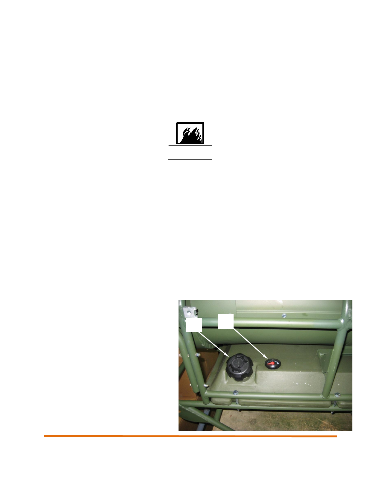
2.5.1 Fueling the Internal Tank (MV60S-EU, MV60T-EU)
Remove the internal fuel tank cap (2) and fill the internal tank with an approved fuel as detailed in section
1.5 of this manual.
Install the internal fuel tank cap (2) and hand tighten securely.
Open the vent on the top of the fuel tank cap
(2).
CAUTION: For fuel tanks with a manual vent.
The fuel tank vent should always be open to
prevent pressure from building up in the fuel
tank. Only close the vent when the heat is
tilted, such as when moving the heater on its
optional wheels.
The fuel level in the tank is displayed on the
fuel gauge to the right of the fuel tank cap (3).
30
 Loading...