

HDT Camfire CV125CG Operation Manual
2
WARNING - SAFETY REQUIREMENTS
IMPORTANT
Read and understand this instruction manual before starting or servicing this heater.
WARNING!
FIRE, EXPLOSION, CARBON MONOXIDE POISONING
Improper use of this heater can result in serious bodily injury due to hazards of fire and explosion,
carbon monoxide poisoning, burn and electrical shock.
WARNING!
CARBON MONOXIDE POISIONING
The heat exchanger must be inspected annually by a qualified service personnel for leaks which could allow
dangerous carbon monoxide gas to enter the shelter. Failure to due so, could cause severe injury or death.
WARNING!
FIRE, EXPLOSION, CARBON MONOXIDE POISONING
Improper adjustment of the air pump can over fire the heater and as a result, compromise the heat
exchanger which can cause serious bodily injury due to hazards of fire and explosion, carbon
monoxide poisoning.
Use only Kerosene, Diesel or Number 1 Fuel Oil, or JP8 can be used for extreme cold conditions.
Never burn gasoline, naphtha, paint thinners, alcohol or other volatile fuels. Fill fuel tank or move
heater only when heater is shut off.
Use only in areas free of flammable vapor or high dust content. Never use heater where gasoline,
paint thinner or other highly flammable vapors are present.
WARNING!
FIRE, EXPLOSION
WARNING!
FIRE, EXPLOSION
3
WARNING!
FIRE, EXPLOSION
Fully drain and ventilate fuel tank before transporting. Fuel tank vent must be open during transport
and storage.
WARNING!
ROTATING MACHINERY
When used with thermostat, heater may start at any time. Do not open access door while heater is
running or plugged in. Remove all power prior to service
WARNING!
SHOCK HAZARD
Use only with electrical voltage and frequency specified on model plate. Do not perform any service
with heater plugged in.
WARNING!
HIGH VOLTAGE
The ignition transformer develops 10,000 volts. Serious injury or death may occur if personnel come
in contact with high voltage lead.
WARNING!
FIRE, EXPLOSION
Do not operate heater without output duct, P/N CAH-1015, properly installed. Ensure hot air outlet is at
least 1.5 meters from combustible materials. Ensure ducts are free from obstructions and sharp
bends.
WARNING!
HOT SURFACE
Parts of the heater become very hot when operating and immediately after operating. The exhaust can
reach temperatures in excess of 1000 degrees Fahrenheit. Severe burns may occur if the heater is not
allowed to cool down properly before servicing.

4

5
INDEX
WARNING – SAFETY REQUIREMENTS ……………………………………………………………
2
SPECIFICATIONS ………………………………………………………………………………………
6
DESCRIPTION …………………………………………………………………………………………..
7
SECTION 1 – INTRODUCTION ……………………………………………………………………….
8
A. General ……………………………………………………………………………………………….
8
B. Principle of Operation
…………………………………………………………………………………
9
10
SECTION 2 – INSTALLATION AND OPERATION .………………………………………………...
A. To Prepare for Operation ………………………………………………………………………….
10
B. Electrical Supply ……………………………………………………………………………………
10
C. Starting the Heater …………………………………………………………………………………
10
D. Stopping the Heater ………………………………………………………………………………..
10
E. Start Up Procedure …………………………………………………………………………………
11
F. Venting Instructions ………………………………………………………………………………..
11
SECTION 3 – MAINTENANCE ………………………………………………………………………..
12
A. Fuel Tank Maintenance ……………………………………………………………………………
12
B. Air Filters …………………………………………………………………………………………….
12
C. Removal of Upper Shell …………………………………………………………………………...
13
D. Cleaning the Fan ……………………………………………………………………………………
14
E. Spark Plug …………………………………………………………………………………………...
14
F. Cleaning the Fuel Filter ……………………………………………………………………………
14
G. Burner removal, Cleaning & Replacement …………………………………………………….
15
H. Post Maintenance Assembly ……………………………………………………………………..
15 15
SECTION 4 – TROUBLE SHOOTING ………………………………………………………………..
16
A. General ……………………………………………………………………………………………….
16
B. Examination …………………………………………………………………………………………
16
C. Test Firing ……………………………………………………………………………………………
16
D. Trouble Shooting …………………………………………………………………………………...
16
TROUBLE SHOOTING CHART ………………………………………………………………………
17-20
SECTION 5 – SERVICE AND REPAIR ………………………………………………………………
21
A. General ……………………………………………………………………………………………….
21
B. Special Tools, Equipment and Supplies ……………………………………………………….
21
C. Thermostat Accessory …………………………………………………………………………….
21
D. Transformer ………………………………………………………………………………………….
21
E. Checking the Motor Starting Circuits …………………………………………………………..
22-24
F. Fan Service …………………………………………………………………………………………..
25
G. Fuel Filter Service ………………………………………………………………………………….
25
H. Burner Head Service ……………………………………………………………………………….
25
I. Air Pump Repair ……………………………………………………………………………………..
26
J. Disassembly …………………………………………………………………………………………
26
K. Replacing the Carbon Blades …………………………………………………………………….
26
L. Replacing the Rotor ………………………………………………………………………………..
26
M. Reassembly of the Air Pump …………………………………………………………………….
27
N. Adjustment of Pump Pressure …………………………………………………………………..
27
O. Reassembly of Heater ……………………………………………………………………………..
27
P. Heat Exchanger Service…………………………………………………………………………….
30
SECTION 6 - ILLUSTRATED PARTS LIST……………………………………………………………
31

6
Figure
Description
Page
1
Schematic of Operations ………………………………………………………….
8
2
Maintenance Points ………………………………………………………………..
12
3
Air Filters ……………………………………………………………………………..
13
4
Spark Plug …………………………………………………………………………...
14
5
Cleaning the Nozzle ………………………………………………………………..
15
6
Fabricated Test Probe ……………………………………………………………..
23
7
Wiring Diagram ……………………………………………………………………...
24
8
Fan Location ………………………………………………………………………...
25
9
Clearance of Rotor ………………………………………………………………….
27
10
Air Pump Pressure Adjustment ………………………………………………….
27
Illustrations

7
CAMFIRE Heater Specifications
Input Heat Rating
BTU/Hour
90,000 – 120,000
Output Ratings
Clean-Air Output, BTU/Hour
60,000 - 70,000
Volume, CFM (Approximate)
600
Other Ratings
Current, Running
4.0 Amps
Voltage
120 VAC
Frequency
60 Hz
Air Pump Pressure
5.0 PSI
Fuel Nozzle
Meter Size
0.65 GPH
Spray Angle
80 Degrees
Fuel
Kerosene, DF1, DF2, Fuel Oil, JP8 Only
Tank Capacity
12.0 Gal (45.5 Litres)
Duct
(Refer to Venting Instructions)
Dimensions
W16” L48” H23”
40 x 122 x 58 cm
Weight (Without Fuel)
74 lbs (33 Kg)
MODEL CV125CG MOD D

8
Description
The CAMFIRE Heater, Model CV125CG MOD D, is a portable, clean-air space heater which relies on an
external input of 120 volts, 60 Hz, single phase power.
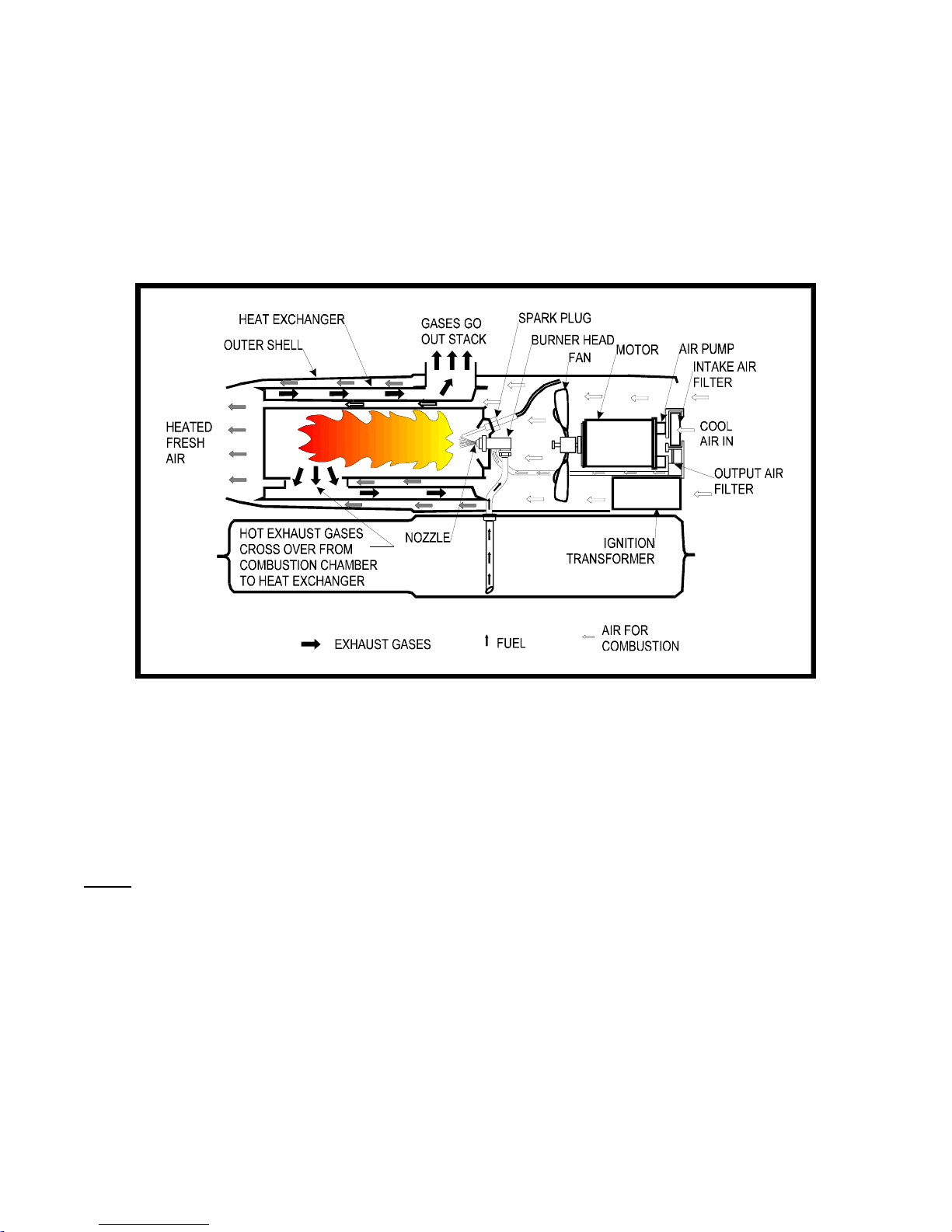
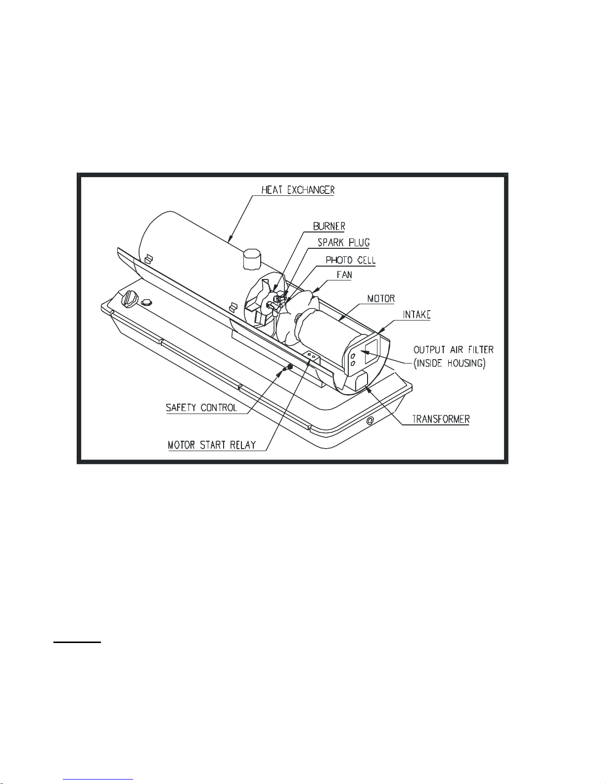
The heart of the heater is a heat exchanger which is supplied with air from a fan driven by a 1/4 horse power
motor. Part of the air from the fan enters the combustion chamber where it mixes with the atomized fuel to
become a combustible mixture. The exhaust gases circulate within the heat exchanger, warming its inner
surfaces, then escape from the heater through a flue pipe adapted to the top of the heater.
The remaining air from the fan passes over and around the combustion chamber and through the heat exchanger
where it is heated, and emerges from the heater as a powerful stream of heated clean air.
The fuel system consists of an air pump mounted on one end of the motor shaft which forces air through the
nozzle. A fan is mounted at the other end of the shaft. The moving air in the nozzle lifts the fuel from the tank by
siphon action and carries it into the combustion chamber.
Filters protect the fuel system at the filler neck and prior to the fuel entering into the spray nozzle.
The electrical control system is protected by a push button type circuit breaker.
A Safety Control Unit, connected to a Photoelectric Cell, shuts down the heater if a flame is not detected in the
combustion chamber after start up. A ”Duct Over-Heat” switch is installed as a safety measure. In the event that
the outlet duct becomes blocked, the switch will shut the heater down.
An optional thermostat accessory, which plugs into the electrical system of the heater, may be set to any desired
temperature. When the temperature of the surrounding air reaches the pre-set
temperature, the thermostat contacts open and cause the heater to shut down. When the air
cools, the thermostat contacts close and the heater recycles.
The heater is designed for hard use in rough environments resulting in a minimum of down time
for repair and maintenance.
9
SECTION 1
INTRODUCTION
A. General
The CAMFIRE’ Heater, Model CV125CG MOD D, is designed to provide fresh, heated air. Electrical power
120VAC 60 or 50 Hz single phase. See cord size, Section 2.
Figure 1 : Schematic of Operations
With Ducts
When using the heater with the thermostat control connected and the optional outlet duct installed, the heater is
”duct temperature limited”. This means that if the duct temperature reaches a pre-determined temperature before
the thermostat has reached its set position, the heater will shut down. Once the heater has shut down it will be
necessary to wait 3 to 5 minutes before pressing the reset control.
NOTE : Check for blockage or restriction of outlet duct before re-starting the heater.

10
B. Principle of Operation
Fuel System
An air pump on one end of the motor shaft forces the air through the nozzle. The moving air lifts fuel from the tank
by a siphon action and carries it into the combustion chamber in a fine spray.
Air System
The air system is divided into two parts, both of which are supplied with air from a fan which is attached to the
other end of the motor.
Part of the air from the fan enters the combustion chamber where it mixes with the atomized fuel to become a
combustible mixture, and also mixes with the burning gases to complete the process of combustion.
The exhaust gases from the combustion chamber circulate within the inner surfaces of the heat exchanger. They
are then ducted out of the heater through the stack adapter on its’ top and out of the heater space through a flue
pipe.
The rest of the air from the fan passes over and around the combustion chamber and through the heat exchanger
where it is heated and emerges from the front of the heater as a powerful stream of heated fresh air, without being
mixed with the products of combustion.
Ignition System
The ignition system consists of a transformer and spark plug. The transformer increases the input voltage to a
very high potential which causes an arc to be drawn between the electrodes of the spark plug. The arc is used to
ignite the fuel and air mixture within the combustion chamber.
Control System
The safety control circuit consists of a duct over heat switch, a light sensitive photocell, and a safety control. The
safety control will trip if the heater fails to ignite or the flame goes out, thereby causing the heater to shut down.
The photocell is used to sense the presence of light due to the flame inside the combustion chamber. It varies its’
electrical resistance in relation to light rays. When under the influence of light, the cell has very low resistance. The
resistance is high when little or no light strikes the light sensitive surface. The flame sensor’s function is to control
the safety control.
A ”duct over-heat” switch is located at the outlet end of the heater. This switch will shut down the heater if the duct
temperature exceeds approximately 275 deg. F.
A thermostat accessory, Part No. CAH-134, may be incorporated into the electrical circuit of the heater. The
thermostat can be set to any desired temperature between 35 deg. F and 95 deg. F. When the temperature of the
surrounding air reaches the pre-set temperature, the thermostat contacts open and cause the heater to shut down.
When the air cools, the thermostat contacts close and the heater recycles.

11
SECTION 2
Installation and Operation
A. To Prepare for Operation
1. Remove all protective material which may have been applied to the heater for shipment.
2. Install optional stack extension, P/N CAH-132.
3. Install output duct, P/N CAH-1015.
4. Open vent on fuel tank.
NOTE: Two air ducts, 15 feet in length and 12 inches in diameter, connect to the inlet and outlet ends of the
heater and move air from the interior of the shelter, through the heater, and back to the interior of the shelter. In
conditions where the outside ambient temperature is above freezing, only the heated air return duct is used. In this
way, the heater draws unheated air from the outside. Operating the heater without input ducting in warmer
temperatures allows the heater to run cooler, thus preventing safety overheat shutdown. Also follow these
guidelines if the heater shuts down on overheat.
B. Electrical Supply
1. Power source 120 volt, 60 or 50 cycle single phase A.C.
2. When using an extension power cord, make sure it is a three wire cord and of adequate size, as listed in the
following table.
EXTENSION CORD SIZE
LENGTH OF CORD WIRE SIZE (AWG)
100 ft NO. 14
200 ft NO. 12
300 ft NO. 10
400 ft NO. 8
450 ft NO. 6
C. Starting the Heater
1. Open fuel filler and check for an adequate fuel supply.
2. Plug the heater power cord into the grounded power supply outlet. There is no on off switch, the heater will start
immediately.
3. If a thermostat accessory is being used, set the dial to the desired temperature. The heater will start
immediately provided that the surrounding air is cooler than the setting of the dial. The heater will continue to
operate until the temperature of the surrounding air reaches the dial setting. It will then shut down and recycle
when the temperature drops.
D. Stopping the Heater
1. Unplug heater power cord from grounded power supply outlet.
2. If the heater is equipped with a thermostat accessory, turn the dial to the”No Heat” position.
12
E. Start up Procedure
1. Set Thermostat to call for heat.
2. Plug the heater power cord into a grounded power supply outlet ; igniter and motor should start immediately.
3. Safety switch lockout will occur if flame is not established during the start up 30 second “trial for ignition” period.
To restart, the safety switch must be manually reset.
4. Control will provide a 5 to 10 second ignition overrun time after the “trial ignition period” to prevent lockouts.
5. Burner will turn off when call for heat is satisfied.
6. If flame failure occurs during a run, the motor will immediately shut off. To restart, the safety switch must be
manually reset.
7. Power loss during a run will cause the burner to safely shut down.
F. Venting Instructions
NOTE: Ensure the heater is vented properly in order to assure proper combustion, and avoid contamination of the
ventilating air with exhaust gases. If a vent is required, use a CAH-132 Stack extension. A vent stack over 12” in
length may create back-pressure on the heater, reducing the combustion efficiency.
G. Transportation and Storage
WARNING!
FIRE, EXPLOSION
Fully drain and ventilate fuel tank before transporting. Fuel tank vent must be open during transport
and storage.
Drain the fuel tank before long term storage. A commercially available fuel stabilizer may be added to the
fuel and run through the heater before draining. If fuel is left in the heater it may gel or turn to varnish
causing hard starting or poor performance the next time the heater used.
Always keep the vent on the fuel tank cap open during operation and storage. The vent may only be
closed while moving the heater with fuel in the tank to a new location to prevent spillage.
13
SECTION 3
Maintenance
Maintenance consists of simple operations the user of the heater can perform to keep the heater running and in
good condition. If ordinary maintenance fails to return the heater to good operating condition, refer to Section 4,
page 14, in this manual for checking and trouble shooting. See Figure 2 for maintenance points.
Figure 2 Maintenance Points
A. Fuel Tank Maintenance
1. Drain the fuel tank after every 150 hours of operation and flush it out with clean fuel. Refill with new, clean fuel.
B. Air Filters
1. Check and clean the intake air filter often. The filter needs cleaning more often if the heater is operated in dusty
conditions. See Figure 3, page 11.
2. To clean the intake air filter, simply pull it out through the opening of the filter housing end cover (see fig. 3),
Wash with mild detergent and hot or cold water, dry thoroughly, and replace in the housing.
CAUTION : Do not oil the filter element
3. Replace the output air filter once each heating season.
4. To reach the output air filter, remove the four screws which attach the filter housing end cover. Lift the output air
filter out. See figure 3.
 Loading...