

Page 1

Operating manual
HDG F20/25/30
HDG F40/50
hdg-bavaria.com
Page 2

Page 3

Operating manual HDG F20-50 - Content
Content
1 Notes on this manual . . . . . . . . . . . . . . . . . . . . . . . . . . . . . . . . . . . . . . . . . . . . . . . . . . . . . . . . 6
1.1 Introduction. . . . . . . . . . . . . . . . . . . . . . . . . . . . . . . . . . . . . . . . . . . . . . . . . . . . . . . . . . . . . . . . . 6
1.2 Glossary. . . . . . . . . . . . . . . . . . . . . . . . . . . . . . . . . . . . . . . . . . . . . . . . . . . . . . . . . . . . . . . . . . . . . 7
2 Safety notes . . . . . . . . . . . . . . . . . . . . . . . . . . . . . . . . . . . . . . . . . . . . . . . . . . . . . . . . . . . . . . . . . 8
2.1 Intended use . . . . . . . . . . . . . . . . . . . . . . . . . . . . . . . . . . . . . . . . . . . . . . . . . . . . . . . . . . . . . . . . 8
2.2 Residual risks . . . . . . . . . . . . . . . . . . . . . . . . . . . . . . . . . . . . . . . . . . . . . . . . . . . . . . . . . . . . . . . . 9
2.3 Warnings and safety symbols used . . . . . . . . . . . . . . . . . . . . . . . . . . . . . . . . . . . . . . . . . .10
2.4 Duty of information . . . . . . . . . . . . . . . . . . . . . . . . . . . . . . . . . . . . . . . . . . . . . . . . . . . . . . . .12
3 Mode of operation . . . . . . . . . . . . . . . . . . . . . . . . . . . . . . . . . . . . . . . . . . . . . . . . . . . . . . . . .13
3.1 Overview. . . . . . . . . . . . . . . . . . . . . . . . . . . . . . . . . . . . . . . . . . . . . . . . . . . . . . . . . . . . . . . . . . .13
3.2 Functional description . . . . . . . . . . . . . . . . . . . . . . . . . . . . . . . . . . . . . . . . . . . . . . . . . . . . . .16
3.3 Technical data . . . . . . . . . . . . . . . . . . . . . . . . . . . . . . . . . . . . . . . . . . . . . . . . . . . . . . . . . . . . .18
3.4 Fuel quality requirements. . . . . . . . . . . . . . . . . . . . . . . . . . . . . . . . . . . . . . . . . . . . . . . . . . .20
Basic system design principles. . . . . . . . . . . . . . . . . . . . . . . . . . . . . . . . . . . . . . . . . . . . . . 8
Basic principles for the content of the operating manual . . . . . . . . . . . . . . . . . . . . 8
Proper and improper operation . . . . . . . . . . . . . . . . . . . . . . . . . . . . . . . . . . . . . . . . . . . .8
Front view HDG F20-50 . . . . . . . . . . . . . . . . . . . . . . . . . . . . . . . . . . . . . . . . . . . . . . . . . . .13
Cross section of HDG F20-50 . . . . . . . . . . . . . . . . . . . . . . . . . . . . . . . . . . . . . . . . . . . . . .14
Rear and side views HDG F20-50. . . . . . . . . . . . . . . . . . . . . . . . . . . . . . . . . . . . . . . . . . .15
Boiler HDG F20-50 . . . . . . . . . . . . . . . . . . . . . . . . . . . . . . . . . . . . . . . . . . . . . . . . . . . . . . . .16
Boiler and weather-compensated heating control HDG controls. . . . . . . . . . . .17
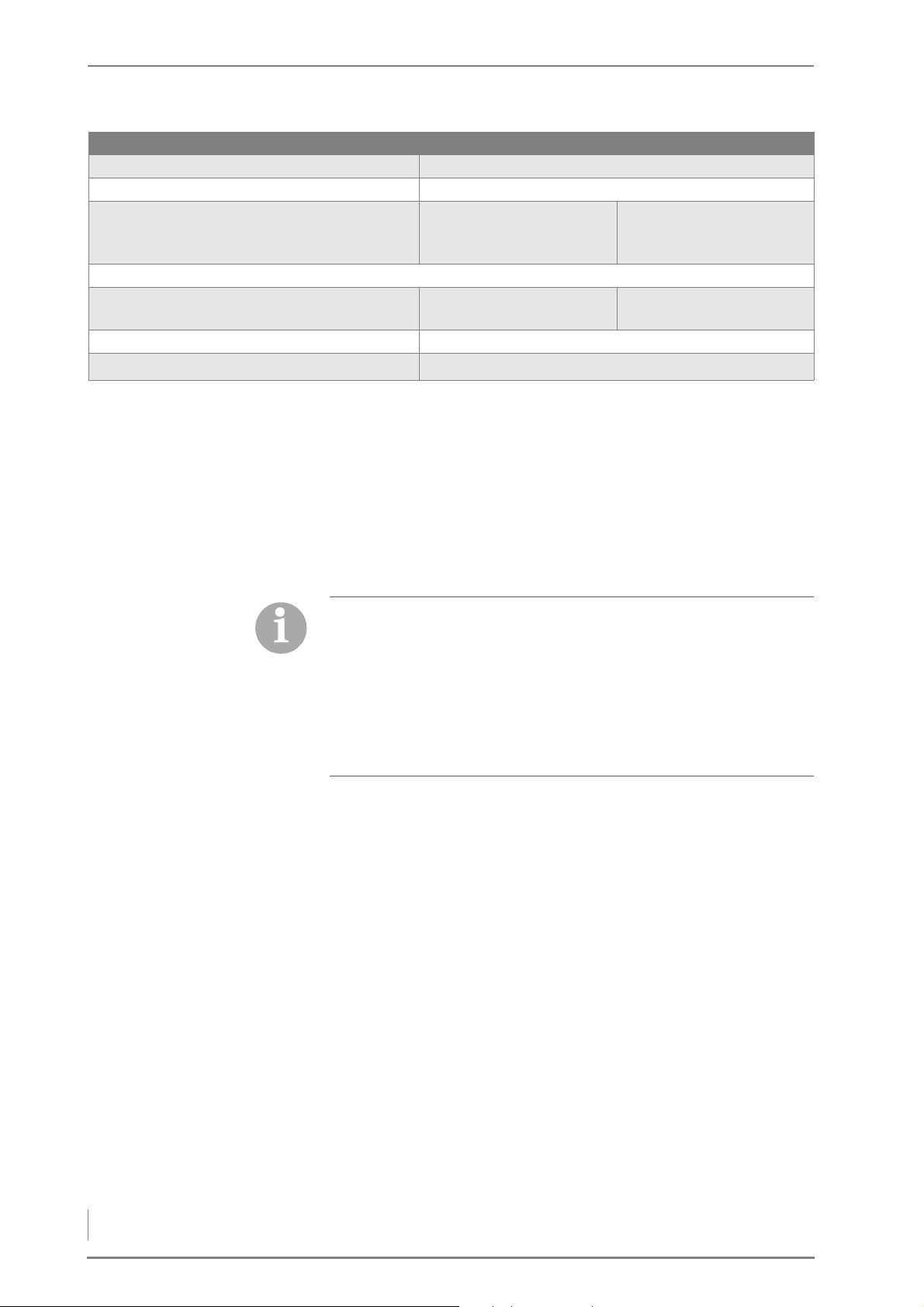
HDG F20/25/30 . . . . . . . . . . . . . . . . . . . . . . . . . . . . . . . . . . . . . . . . . . . . . . . . . . . . . . . . . . .18
HDG F40/50 . . . . . . . . . . . . . . . . . . . . . . . . . . . . . . . . . . . . . . . . . . . . . . . . . . . . . . . . . . . . . .19
Log wood . . . . . . . . . . . . . . . . . . . . . . . . . . . . . . . . . . . . . . . . . . . . . . . . . . . . . . . . . . . . . . . .20
Pressed wood briquettes . . . . . . . . . . . . . . . . . . . . . . . . . . . . . . . . . . . . . . . . . . . . . . . . . .21
Recommended fuel . . . . . . . . . . . . . . . . . . . . . . . . . . . . . . . . . . . . . . . . . . . . . . . . . . . . . . .21
Permitted fuel in accordance with 1st Federal Emission Control
Ordinance (Germany) . . . . . . . . . . . . . . . . . . . . . . . . . . . . . . . . . . . . . . . . . . . . . . . . . . . . .22
4 Planning and installation . . . . . . . . . . . . . . . . . . . . . . . . . . . . . . . . . . . . . . . . . . . . . . . . . . .23
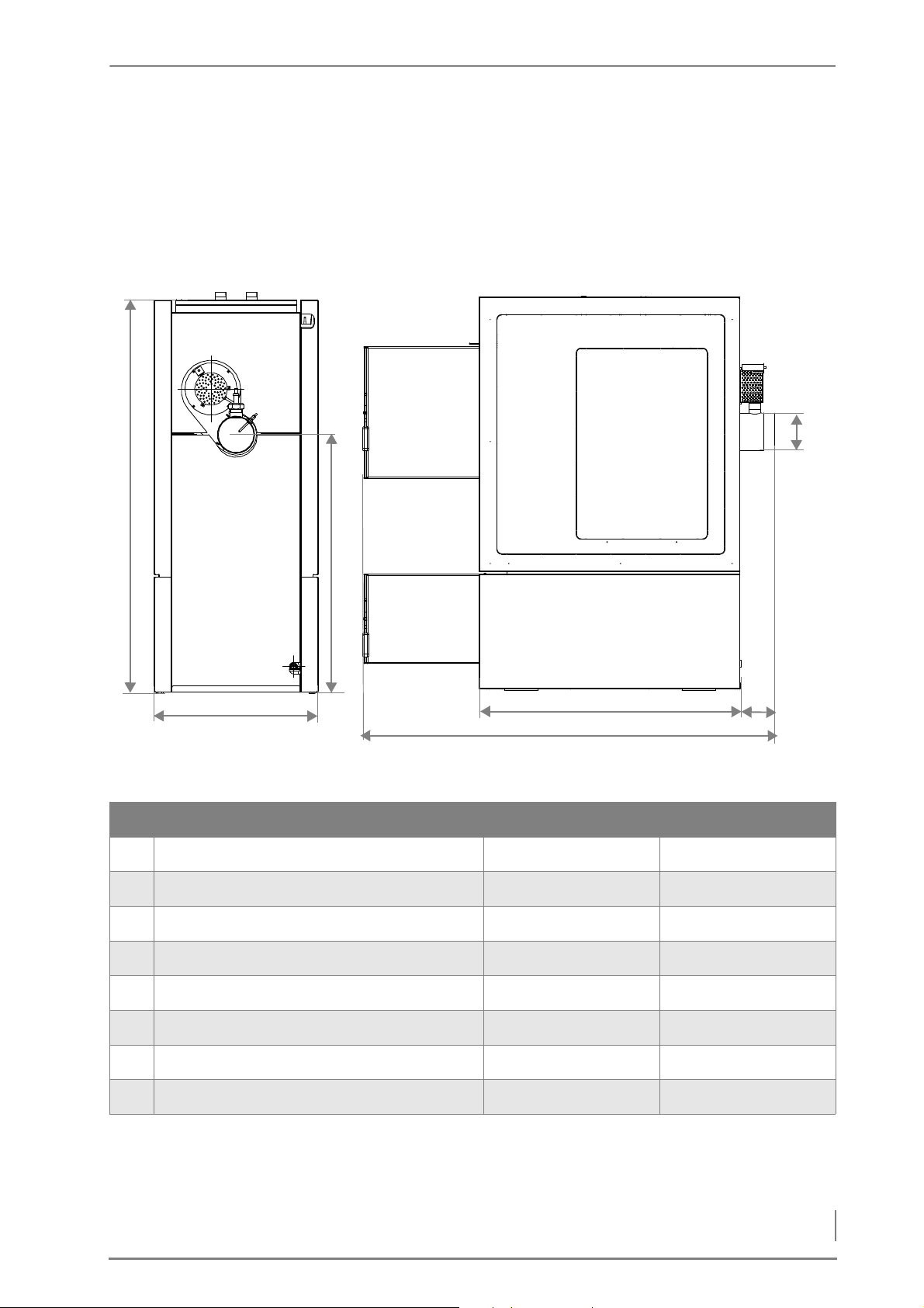
4.1 Dimensions . . . . . . . . . . . . . . . . . . . . . . . . . . . . . . . . . . . . . . . . . . . . . . . . . . . . . . . . . . . . . . . .23
4.2 Structural requirements . . . . . . . . . . . . . . . . . . . . . . . . . . . . . . . . . . . . . . . . . . . . . . . . . . . .24
Boiler installation site . . . . . . . . . . . . . . . . . . . . . . . . . . . . . . . . . . . . . . . . . . . . . . . . . . . . .24
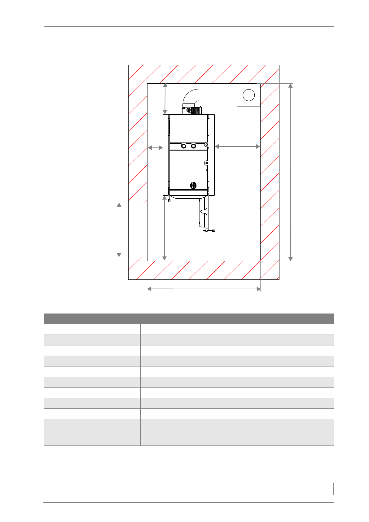
Required room sizes and minimum clearances . . . . . . . . . . . . . . . . . . . . . . . . . . . . .24
4.3 Connections . . . . . . . . . . . . . . . . . . . . . . . . . . . . . . . . . . . . . . . . . . . . . . . . . . . . . . . . . . . . . . .26
Chimney . . . . . . . . . . . . . . . . . . . . . . . . . . . . . . . . . . . . . . . . . . . . . . . . . . . . . . . . . . . . . . . . .26
Electrical system . . . . . . . . . . . . . . . . . . . . . . . . . . . . . . . . . . . . . . . . . . . . . . . . . . . . . . . . . .28
Water. . . . . . . . . . . . . . . . . . . . . . . . . . . . . . . . . . . . . . . . . . . . . . . . . . . . . . . . . . . . . . . . . . . . .28
4.4 Hydraulic connection . . . . . . . . . . . . . . . . . . . . . . . . . . . . . . . . . . . . . . . . . . . . . . . . . . . . . . .29
4.5 Scope of delivery . . . . . . . . . . . . . . . . . . . . . . . . . . . . . . . . . . . . . . . . . . . . . . . . . . . . . . . . . . .30
4.6 Installing the heating system . . . . . . . . . . . . . . . . . . . . . . . . . . . . . . . . . . . . . . . . . . . . . . .30
3
Page 4

Operating manual HDG F20-50 - Content
Requirements. . . . . . . . . . . . . . . . . . . . . . . . . . . . . . . . . . . . . . . . . . . . . . . . . . . . . . . . . . . . 30
Installing the boiler . . . . . . . . . . . . . . . . . . . . . . . . . . . . . . . . . . . . . . . . . . . . . . . . . . . . . . 31
Installing hydraulic connections . . . . . . . . . . . . . . . . . . . . . . . . . . . . . . . . . . . . . . . . . . 33
Installing the HDG controls control unit . . . . . . . . . . . . . . . . . . . . . . . . . . . . . . . . . . . 35
Installing the automatic ignition . . . . . . . . . . . . . . . . . . . . . . . . . . . . . . . . . . . . . . . . . 37
Installing the automatic cleaning system . . . . . . . . . . . . . . . . . . . . . . . . . . . . . . . . . 39
Fitting the cladding . . . . . . . . . . . . . . . . . . . . . . . . . . . . . . . . . . . . . . . . . . . . . . . . . . . . . . 40
4.7 Connecting the chimney. . . . . . . . . . . . . . . . . . . . . . . . . . . . . . . . . . . . . . . . . . . . . . . . . . . 45
4.8 Electrical system. . . . . . . . . . . . . . . . . . . . . . . . . . . . . . . . . . . . . . . . . . . . . . . . . . . . . . . . . . . 45
4.9 Water . . . . . . . . . . . . . . . . . . . . . . . . . . . . . . . . . . . . . . . . . . . . . . . . . . . . . . . . . . . . . . . . . . . . . 45
4.10 Connecting the thermal safety device . . . . . . . . . . . . . . . . . . . . . . . . . . . . . . . . . . . . . . 46
5 Commissioning. . . . . . . . . . . . . . . . . . . . . . . . . . . . . . . . . . . . . . . . . . . . . . . . . . . . . . . . . . . . 48
5.1 Requirements . . . . . . . . . . . . . . . . . . . . . . . . . . . . . . . . . . . . . . . . . . . . . . . . . . . . . . . . . . . . . 48
5.2 Procedure . . . . . . . . . . . . . . . . . . . . . . . . . . . . . . . . . . . . . . . . . . . . . . . . . . . . . . . . . . . . . . . . . 48
Switching on the heating system . . . . . . . . . . . . . . . . . . . . . . . . . . . . . . . . . . . . . . . . . 49
Testing system components. . . . . . . . . . . . . . . . . . . . . . . . . . . . . . . . . . . . . . . . . . . . . . 49
6 Using the heating system . . . . . . . . . . . . . . . . . . . . . . . . . . . . . . . . . . . . . . . . . . . . . . . . . . 50
6.1 Control unit for HDG controls . . . . . . . . . . . . . . . . . . . . . . . . . . . . . . . . . . . . . . . . . . . . . . 50
6.2 Switching on the heating system. . . . . . . . . . . . . . . . . . . . . . . . . . . . . . . . . . . . . . . . . . . 50
Requirements. . . . . . . . . . . . . . . . . . . . . . . . . . . . . . . . . . . . . . . . . . . . . . . . . . . . . . . . . . . . 50
Emergency heating switch . . . . . . . . . . . . . . . . . . . . . . . . . . . . . . . . . . . . . . . . . . . . . . . 50
Fuel selection . . . . . . . . . . . . . . . . . . . . . . . . . . . . . . . . . . . . . . . . . . . . . . . . . . . . . . . . . . . . 51
6.3 Heating up the system . . . . . . . . . . . . . . . . . . . . . . . . . . . . . . . . . . . . . . . . . . . . . . . . . . . . . 51
General information. . . . . . . . . . . . . . . . . . . . . . . . . . . . . . . . . . . . . . . . . . . . . . . . . . . . . . 51
Procedure . . . . . . . . . . . . . . . . . . . . . . . . . . . . . . . . . . . . . . . . . . . . . . . . . . . . . . . . . . . . . . . 52
6.4 Performing a chimney sweep measurement . . . . . . . . . . . . . . . . . . . . . . . . . . . . . . . . 60
Before the test . . . . . . . . . . . . . . . . . . . . . . . . . . . . . . . . . . . . . . . . . . . . . . . . . . . . . . . . . . . 61
On the day of the test . . . . . . . . . . . . . . . . . . . . . . . . . . . . . . . . . . . . . . . . . . . . . . . . . . . . 61
During the test. . . . . . . . . . . . . . . . . . . . . . . . . . . . . . . . . . . . . . . . . . . . . . . . . . . . . . . . . . . 62
6.5 Switching off the heating system for repair work . . . . . . . . . . . . . . . . . . . . . . . . . . . 64
6.6 Troubleshooting . . . . . . . . . . . . . . . . . . . . . . . . . . . . . . . . . . . . . . . . . . . . . . . . . . . . . . . . . . 64
7 Cleaning and servicing the heating system . . . . . . . . . . . . . . . . . . . . . . . . . . . . . . . . . 65
7.1 Cleaning and servicing schedule . . . . . . . . . . . . . . . . . . . . . . . . . . . . . . . . . . . . . . . . . . . 65
7.2 Procedure . . . . . . . . . . . . . . . . . . . . . . . . . . . . . . . . . . . . . . . . . . . . . . . . . . . . . . . . . . . . . . . . . 66
4
Generally applicable safety instructions. . . . . . . . . . . . . . . . . . . . . . . . . . . . . . . . . . . 66
Cleaning tools . . . . . . . . . . . . . . . . . . . . . . . . . . . . . . . . . . . . . . . . . . . . . . . . . . . . . . . . . . . 67
Cleaning the fuel chamber and secondary air openings . . . . . . . . . . . . . . . . . . . 67
Cleaning the secondary combustion chamber and the ash compartment . . 69
Checking and cleaning the lambda sensor . . . . . . . . . . . . . . . . . . . . . . . . . . . . . . . . 70
Cleaning the flue gas temperature sensor. . . . . . . . . . . . . . . . . . . . . . . . . . . . . . . . . 71
Cleaning the flue gas pipe. . . . . . . . . . . . . . . . . . . . . . . . . . . . . . . . . . . . . . . . . . . . . . . . 72
Cleaning the cleaning system, heat exchanger surfaces and flue gas flap. . . 72
Cleaning the flue gas fan . . . . . . . . . . . . . . . . . . . . . . . . . . . . . . . . . . . . . . . . . . . . . . . . . 76
Cleaning the air control unit . . . . . . . . . . . . . . . . . . . . . . . . . . . . . . . . . . . . . . . . . . . . . . 77
Cleaning the panels . . . . . . . . . . . . . . . . . . . . . . . . . . . . . . . . . . . . . . . . . . . . . . . . . . . . . . 77
Page 5

Operating manual HDG F20-50 - Content
Checking the doors are tight . . . . . . . . . . . . . . . . . . . . . . . . . . . . . . . . . . . . . . . . . . . . . .78
Cleaning the ignition fan . . . . . . . . . . . . . . . . . . . . . . . . . . . . . . . . . . . . . . . . . . . . . . . . . .80
8 Notes on dismantling and disposal . . . . . . . . . . . . . . . . . . . . . . . . . . . . . . . . . . . . . . . . . .82
8.1 Dismantling . . . . . . . . . . . . . . . . . . . . . . . . . . . . . . . . . . . . . . . . . . . . . . . . . . . . . . . . . . . . . . . .82
8.2 Disposal. . . . . . . . . . . . . . . . . . . . . . . . . . . . . . . . . . . . . . . . . . . . . . . . . . . . . . . . . . . . . . . . . . . .83
9 Declaration of Conformity . . . . . . . . . . . . . . . . . . . . . . . . . . . . . . . . . . . . . . . . . . . . . . . . . .84
10 Index . . . . . . . . . . . . . . . . . . . . . . . . . . . . . . . . . . . . . . . . . . . . . . . . . . . . . . . . . . . . . . . . . . . . . .85
5
Page 6

1 Notes on this manual – Introduction
1 Notes on this manual
1.1 Introduction
SAFE AND SIMPLE OPERATION This Operating manual contains important instructions on the boiler
• HDG F20/25/30
• HDG F40/50
and how to operate it properly and safely. Following these
instructions helps to avoid dangers, prevent repair costs and
downtimes, maintain reliability and extend the life expectancy of the
heating system.
EADING THE OPERATING
R
MANUAL
T
ECHNICAL CHANGES We continuously develop and improve our boilers. The information
C
OPYRIGHT Written permission is required from HDG Bavaria GmbH for
G
UARANTEE The terms and conditions of the guarantee of your boiler can be
S
YMBOLS USED In this Operating manual, the following designations and symbols
This Operating manual must be read and observed by everyone who
operates or works on the HDG F20-50.
in this edition was correct at the time of going to press.
We reserve the right to make changes which may then differ from the
technical details and illustrations in this Operating manual.
reprinting, storage in a data-processing system or transmission by
electronic, mechanical, photographic or any other means, and for
copies or translations of this publication, in whole or in part.
found in the enclosed information sheet.
are used for particularly important information:
1. Instructions to the operator
2. Work through the steps in the sequence specified.
✓ Result of the action described
✎ Cross reference for more explanation
• List
–List
6
Page 7

1 Notes on this manual – Glossary
1.2 Glossary
Term Explanation
Actuator This is a component which carries out a certain function in the
heating system, e.g. flue gas fan.
Central module Pre-fabricated plug board for electrical components.
Display Display on the control unit HDG controls.
Flue gas fan Creates a vacuum inside the boiler and provides the boiler with air
for combustion.
HDG controls Boiler and heating system controller.
HDG F20-50 Boiler for burning untreated wood.
HDG F20-50 Hybrid Boiler for burning untreated wood. The HDG F Hybrid is also
intended for combined used with a HDG K Hybrid pellt unit
Lambda sensor This is an electrical component which monitors residual oxygen
levels in the flue gas.
Safety temperature limiter An automatic device that interrupts and locks the supply of energy
and combustion air when the maximum permissible boiler
temperature is reached. The energy supply or combustion air
supply can only be re-enabled after the boiler temperature has
fallen below a preset limit and has been reset by hand or by means
of a tool.
Sensor Monitors certain parameters (e.g. temperature) and forwards them
to the control system for analysis.
Thermal safety device Safety device that allows cold water to flow through the safety
heat exchanger if the boiler becomes too hot.
Table 1/1 - Glossary
7
Page 8

2 Safety notes – Intended use
2 Safety notes
2.1 Intended use
BASIC SYSTEM DESIGN PRINCIPLES
BASIC PRINCIPLES The heating system was built using state-of-the-art technology and
conforms to recognised safety regulations. Nevertheless, there is still
a risk of injury or death to users or bystanders, and of adverse effects
upon the heating system or upon other material goods. Have your
specialist heating company provide you with detailed instructions on the operation of the heating system.
U
SING THE HEATING SYSTEM Only use the heating system when it is in perfect condition. Use it
properly, as intended, be aware of safety and hazards, and observe
the Operating manual. Have any faults which could impair safety
fixed immediately.
This device can be used by children over 8 years old and people with
reduced physical, sensory or mental capabilities or a lack of experience and knowledge, provided they are supervised or have been instructed on the safe use of the device and understand the resulting
risks. Children may not play with the device. Cleaning and user maintenance must not be carried out by children without supervision.
BASIC PRINCIPLES FOR THE CONTENT OF THE OPERATING MANUAL
SCOPE The content of this operating manual is intended exclusively for the
planning, installation and operation of the HDG F20-50 boiler. The
further implementation of applicable standards and guidelines, for
example regarding installation of the heating system (pipework,
etc.), is not part of this operating manual. HDG Bavaria does not assume any liability for this.
PROPER AND IMPROPER OPERATION
PURPOSE OF THE HEATING
SYSTEM
The HDG F20-50 boiler is designed for the standard operation of
burning untreated wood, for example in the form of split logs and
pressed wood briquettes in hot-water heating systems.
Any other application is considered improper use. The manufacturer
will accept no liability for any damage resulting from improper use.
The operator bears sole responsibility in such cases.
Proper use includes adherence to the installation, operation and
maintenance requirements specified by the manufacturer.
8
Page 9
2 Safety notes – Residual risks
Modification of the specified operating values will affect the heating
system’s control programme and could lead to malfunctions. Only
trained maintenance and operating personnel may undertake modifications to the operating values.
For more information on fuel, see chapter “3 Mode of operation”,
section “3.4 Fuel quality requirements”.
2.2 Residual risks
Despite all precautions, the following residual risks remain:
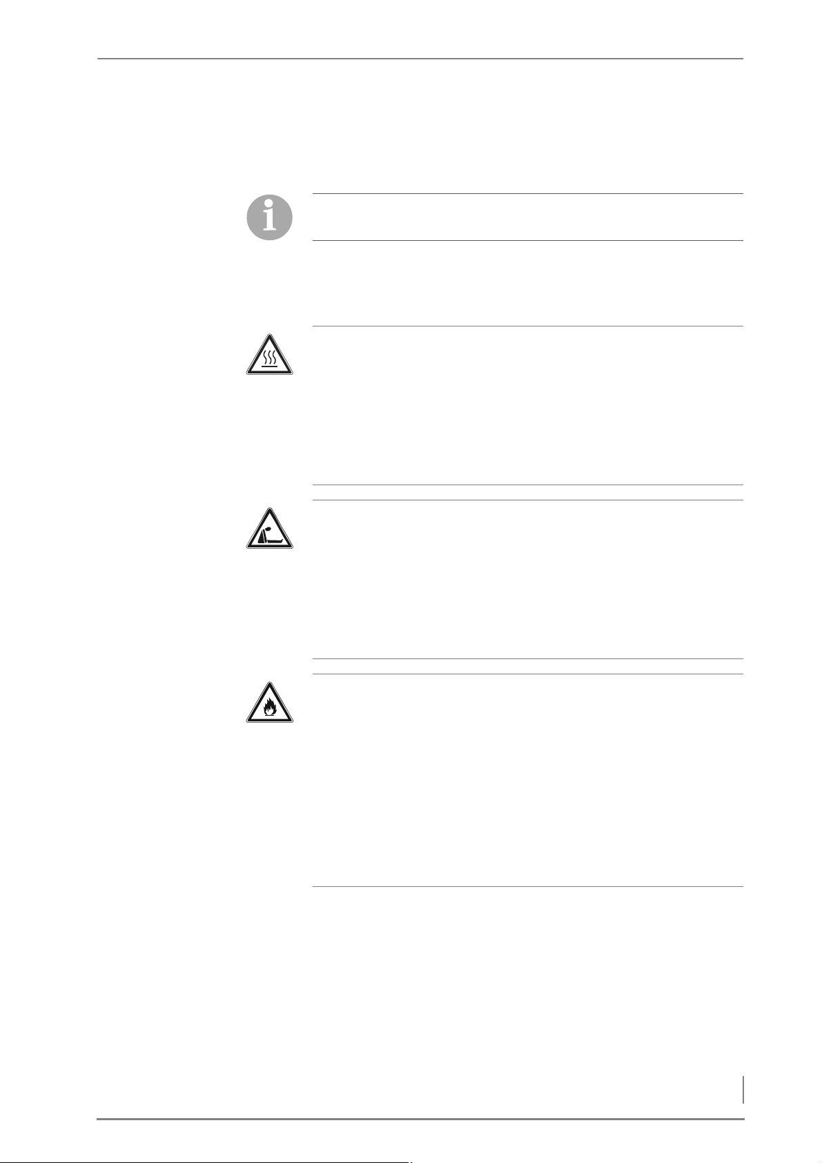
Caution!
Hot surfaces
Contact with the hot surfaces of the boiler (e.g. inside doors, flue
pipe, etc.) can result in burns. Even after the boiler is switched off,
the surfaces only cool down slowly.
Wait until the boiler has cooled down before touching non-insulated components.
Danger!
Danger of asphyxiation due to carbon monoxide
If the boiler is in operation, carbon monoxide can be emitted
through the open doors or lids.
Always keep the doors and lids closed. Only open them when the
boiler has finished burning. Do not leave them open any longer
than necessary and never leave them open unattended.
Warning!
Danger of fire
When the heating system is in operation, open doors and lids constitute a fire hazard. Furthermore, combustion residue (ash, charcoal etc.) can reignite after being removed from the boiler.
Always keep the doors and lids closed. Only open them when the
boiler has finished burning. Do not leave them open any longer
than necessary and never leave them open unattended. Put the annealed combustion residue in the ash pan of a non-flammable and
closable container.
9
Page 10
2 Safety notes – Warnings and safety symbols used
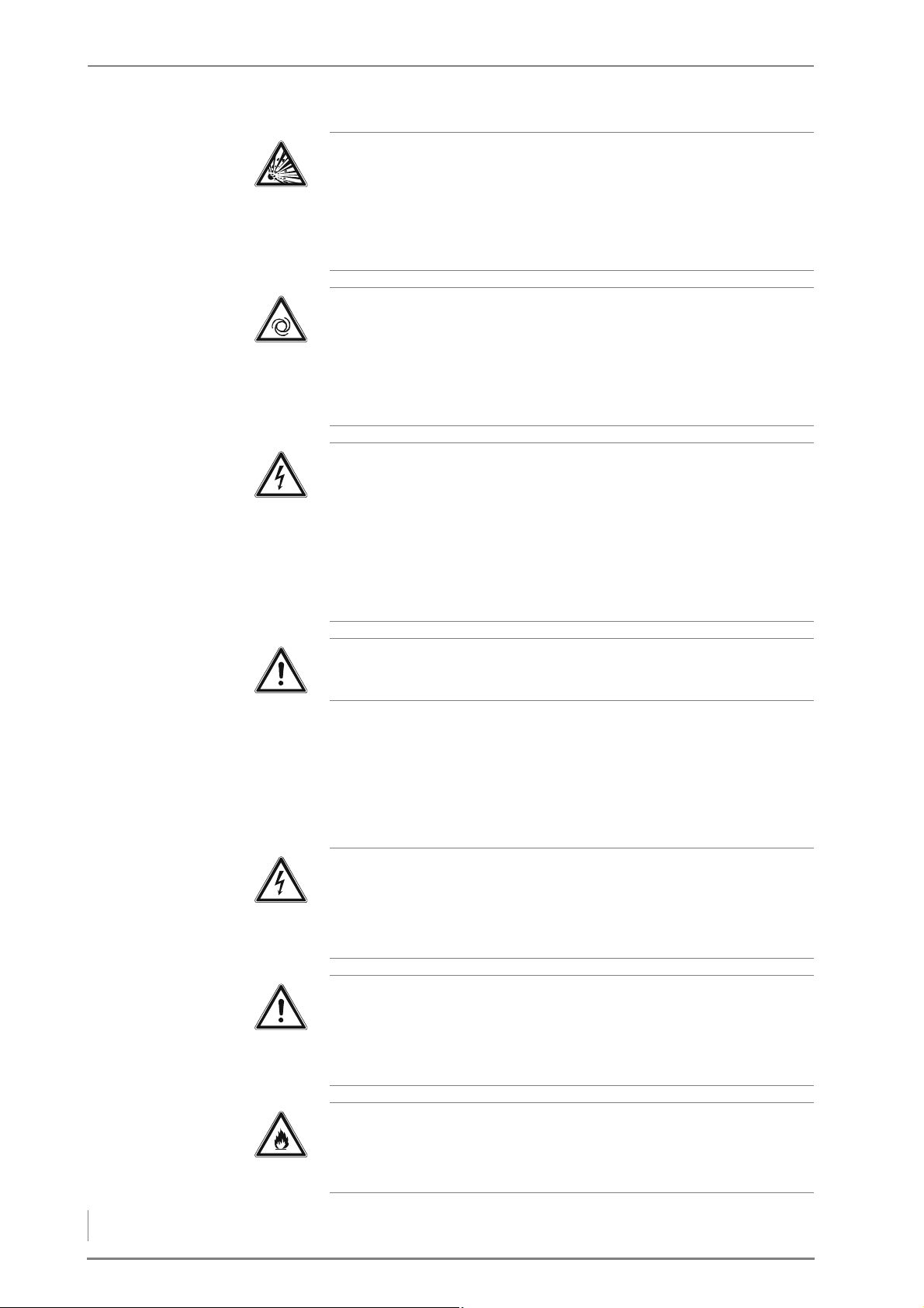
Danger!
Danger of explosion
A concentration of carbon monoxide that is too high can result in
an explosion.
Observe the flue draught requirement of the chimney.
Caution!
Risk of injury from automatically driven components
Working on the flue gas fan can lead to hand injuries due to the
moving parts.
When working on the flue gas fan, disconnect it from the mains.
Danger!
Electric shock
Working on live components (such as the plug board) can result in
an electric shock.
Work on the live components may only be carried out by a qualified
electrician. Make sure the system is disconnected from the mains
and prevented from being switched on again.
Warning!
The boiler is under pressure.
2.3 Warnings and safety symbols used
The following warnings and safety symbols are used in this Operating manual:
Danger!
Dangerous electrical current or voltage
Work in areas marked with this symbol may only be performed by a
qualified electrician.
Warning!
Hazardous area
Working in areas marked with this symbol can lead to serious injuries or to extensive material damage.
10
Caution!
Hot surfaces
Working in areas marked with this symbol can lead to burns.
Page 11
2 Safety notes – Warnings and safety symbols used
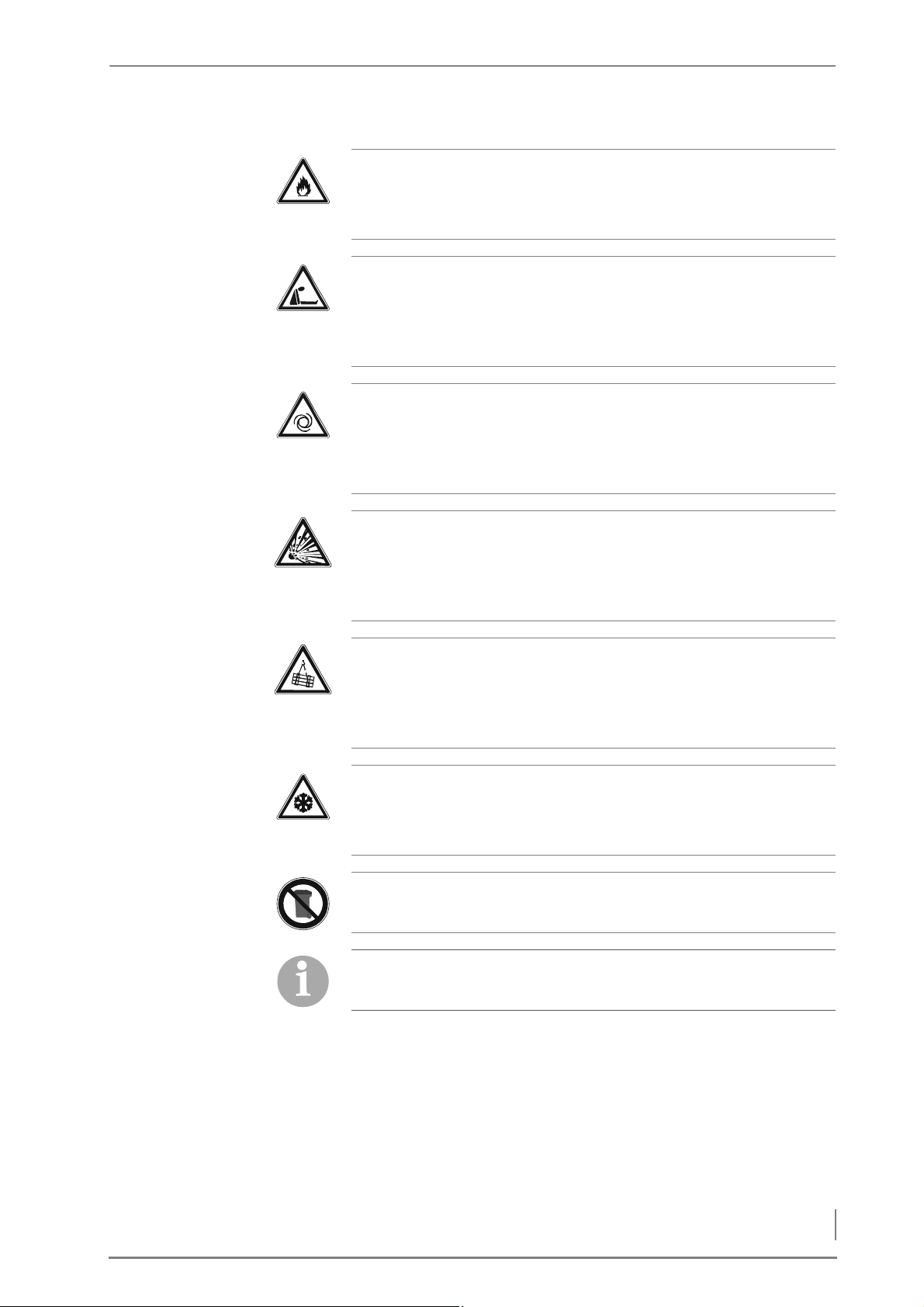
Warning!
Danger of fire
Working in areas marked with this symbol can lead to a fire.
Danger!
Danger of asphyxiation due to lack of oxygen
When working in areas marked with this symbol, there is a danger
of asphyxiation due to high concentrations of carbon monoxide.
Warning!
Automatic start-up
Working in areas marked with this symbol can lead to injuries due
to automatic start-up.
Danger!
Danger of explosion
A concentration of carbon monoxide that is too high can result in
an explosion.
Caution!
Danger from suspended loads
Working in areas with this symbol may involve danger from falling
objects.
Important!
Frost danger
Only install the heating system in a frost-proof room.
Instructions regarding disposal
Additional information for the operator
11
Page 12

2 Safety notes – Duty of information
2.4 Duty of information
READING THE OPERATING
MANUAL
Any person performing tasks on this system must read the Operating
manual prior to beginning work, particularly the chapter “2 Safety
notes”.
This is especially important for persons who only occasionally work
on the heating system, for example when cleaning or servicing it.
The Operating manual must always be kept readily accessible at the
place where heating system is installed.
12
Page 13
3 Mode of operation – Overview
3 Mode of operation
5
2
8
9
1
4
7
6
3
10
3.1 Overview
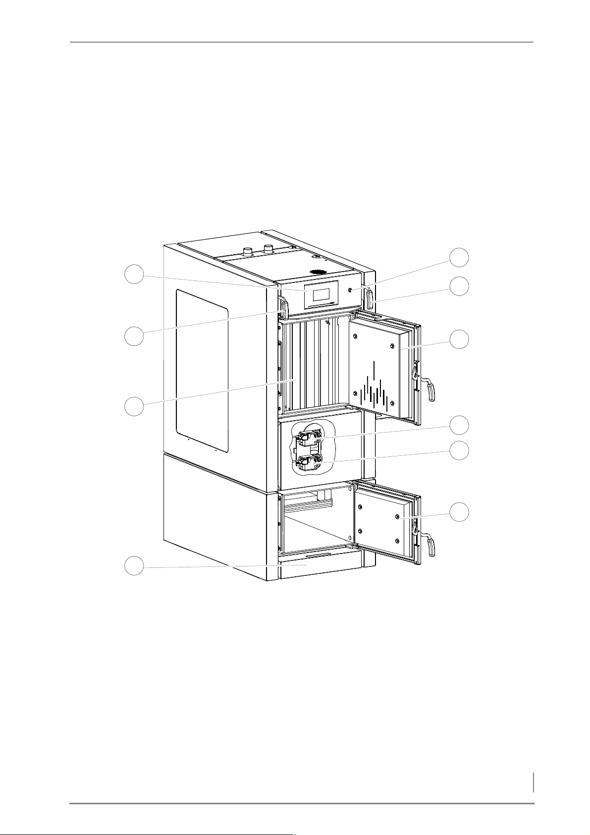
FRONT VIEW HDG F20-50
Figure 3/1 - Front view HDG F20-50
1 Control unitHDG Control Touch
2 Flue gas flap actuating handle
3Fuel chamber
4Ash pan
5 Combustion chamber door
6 Actuator secondary air
7 Actuator primary air
8 Fuel chamber door
9 Cleaning system actuating handle
10 Overheat cut-off device release button
13
Page 14
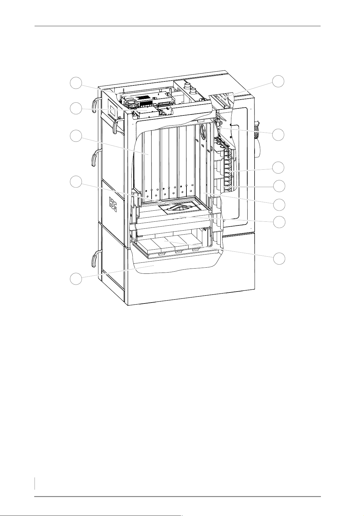
3 Mode of operation – Overview
CROSS SECTION OF HDG F20-50
6
7
11
9
8
12
5
4
2
1
3
10
Figure 3/2 - Cross section of HDG F20-50
1Central module
2 EM4 extension module (optional)
3Side panels
4 Burner nozzle
5Ash compartment
6 Combustion chamber
7 Nozzle brick
8Back panels
9 Tubular heat exchanger
10 Cleaning turbulators
11 Flue gas flap
12 Cleaning shaft lid
14
Page 15
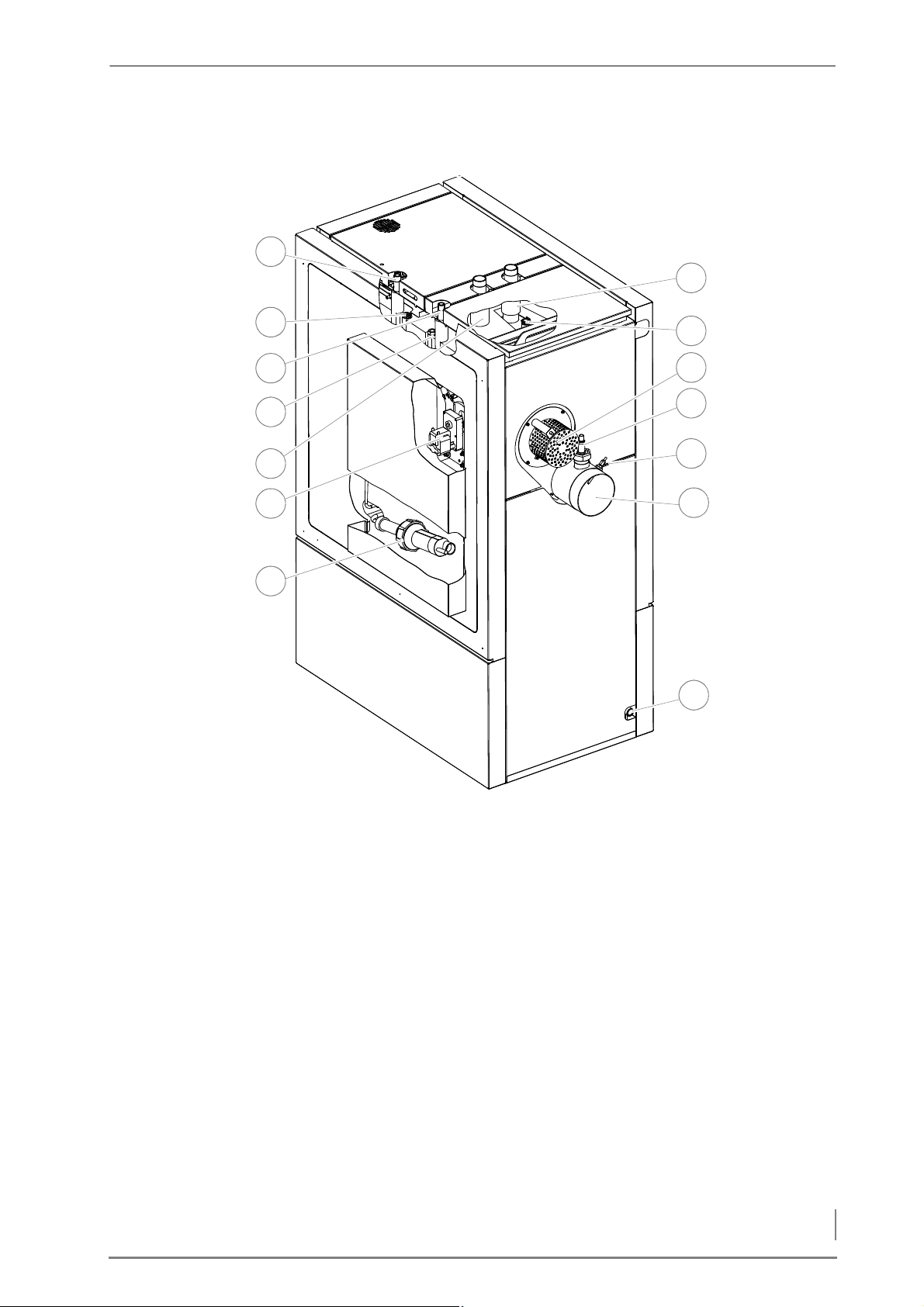
3 Mode of operation – Overview
REAR AND SIDE VIEWS HDG F20-50
4
8
9
3
1
14
7
5
2
11
13
6
10
12
Figure 3/3 - Rear and side views HDG F20-50
1 Safety heat exchanger inlet (DN 15 male)
2 Immersion sleeve for boiler temperature and STL sensor
3 Safety heat exchanger outlet (DN 15 male)
4 Connection of immersion sleeve for thermal
safety device (DN 15 IG)
5 Supply connection (DN 32 inside thread)
6 Cleaning motor (optional)
7 Ignition fan (optional)
8 Filling/draining connection (DN 15 IG)
9 Flue pipe connection 150 mm
10 Flue gas temperature sensor
11 Lambda sensor
12 Flue gas fan
13 Immersion sleeve for return temperature sensor
14 Return connection (DN 32 inside thread)
15
Page 16
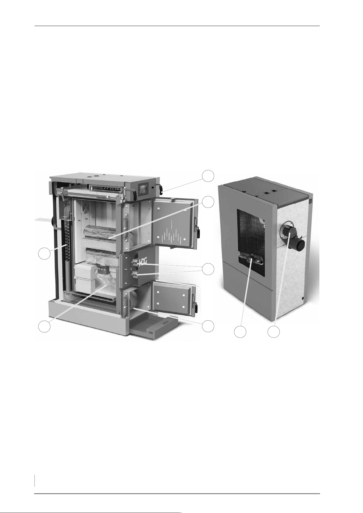
3 Mode of operation – Functional description
3.2 Functional description
4
1
6
8
2
3
5
7
BOILER HDG F20-50
GENERAL INFORMATION The HDG F20-50 is a special boiler for the firing of wood up to 50 cm
in length. The HDG controls system regulates the combustion and
output as well as the weather-compensated heating. The HDG F2050 boiler and the HDG controls system are harmonised with one
another and form a functional unit. This enables wood to be
converted into heat energy in an environmentally sound and
convenient manner.
C
OMBUSTION PROCESS
16
Figure 3/4 - Boiler HDG F20-50
Inside the HDG F20-50 boiler, fuel which has been manually placed in
the fuel chamber (4) and ignited is degassed through the addition of
primary air. It can also be ignited automatically using the ignition fan
(7). The resulting wood gas is mixed with secondary air in the
combustion chamber (2) where it is burnt off.
Ashes are collected in the large ash compartments (6) for
combustion ash and fly ash.
The air necessary for combustion is supplied as required via the
suction fan (8) and two actuators (5) with metering mechanisms.
The lambda sensor, the boiler temperature sensor and the flue gas
temperature sensor are used to do the following:
• To continuously monitor the firing
• To adjust the boiler output
Page 17

3 Mode of operation – Functional description
• To minimise emissions
• To optimise boiler efficiency
LEANING SYSTEM When the actuating handle (3) of the cleaning system is pulled, the
C
heat exchanger surfaces are cleaned by the turbulators (1) located
inside. The turbulators can also be moved automatically using the
drive motor.
BOILER AND WEATHER-COMPENSATED HEATING CONTROL HDG
CONTROLS
BOILER CONTROL UNIT The HDG controls boiler control unit is the electronic hub of the
boiler. It consists of the ready-to-use control panel and control unit
HDG Control Touch on the front of the boiler. Using the control unit,
you can regulate the boiler and call up information on the current
process.
H
EATING CIRCUIT CONTROL The HDG controls controls the entire energy management of the
heating system including the following, depending on the version:
• Accumulator management
• Weather-compensated heating circuits
• Domestic hot water heating
• External heat source
• Local heating transfer (mains pump)
• Solar system for hot water and support of the heating system
✎ For a description of the HDG controls boiler and weather-
compensated heating control, refer to the “HDG controls”
operating manual.
17
Page 18
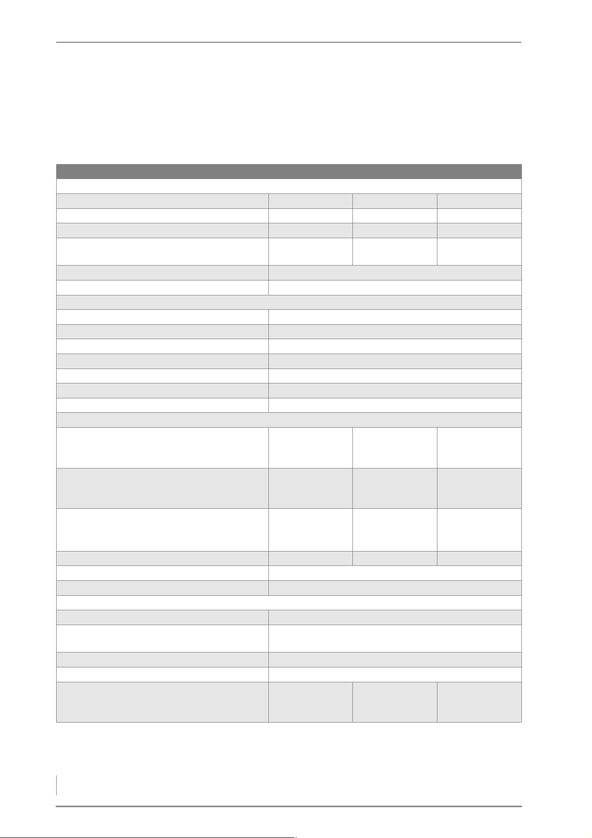
3 Mode of operation – Technical data
3.3 Technical data
HDG F20/25/30
Type of boiler HDG F20 HDG F25 HDG F30
Performance data (measured according to DIN EN 303-5)
Nominal thermal power 20 kW 25 kW 30 kW
Minimum thermal power 15 kW 15 kW 15 kW
Boiler efficiency at nominal thermal power 93.8 % 93.4 % 93.0 %
Electrical power consumption at nominal
thermal power
Voltage / frequency AC 1 x 230 V / 50 Hz
Back-up fuse 10 A
General boiler data
Boiler class 5
Maximum permissible operating pressure 3 bar
Maximum supply temperature 95 °C*
Minimum return temperature 60 °C
Water capacity 125 l
Fuel chamber capacity 155 l
Weight 670 kg
Layout data for flue calculation (DIN EN 13384-1)
Flue gas temperature (Tw) at
Nominal thermal power / lowest thermal
power
Flue gas mass flow at
Nominal thermal power / lowest thermal
power
CO2content at
Nominal thermal power / lowest thermal
power
Required flue draught (Pw) 10 Pa 10 Pa 10 Pa
Diameter of flue pipe connection 150 mm
Height to centre of flue gas connecting pipe 1040 mm
Water-side connections
Supply and return connections (bushing) DN 32, inside thread
Safety heat exchanger connections
(bushing)
Connection for filling/draining (bushing) DN 15, inside thread
Recommended pipe dimensions (minimum) DN 32
Water-side resistance at nominal thermal
power
10 K / 20 K
Table 3/1 - HDG F20/25/30 technical data
78 W 82 W 85 W
120 °C / 120 °C 130 °C / 120 °C 140 °C / 120 °C
0.013 /0.010 kg/s 0.013 / 0.010 kg/s 0.013 / 0.010 kg/s
14.2 % / 13.3 % 14.2 % / 13.3 % 14.2 % / 13.3 %
DN 15, outside thread
1600 Pa / 400 Pa 2000 Pa / 500 Pa 2400 Pa / 600 Pa
18
Page 19

3 Mode of operation – Technical data
Type of boiler HDG F20 HDG F25 HDG F30
Other information
Combustion duration per filling in terms of
fuel recommendation, approx.
Beech: up to 7 h
Spruce: up to 6 h
Beech: up to 6 h
Spruce: up to 5 h
Beech: up to 5 h
Spruce: up to 4 h
Sound pressure level < 70 dB(A)
Min. Air inlet cross section
150 cm
Table 3/1 - HDG F20/25/30 technical data
2
*Maximum operating temperatures of up to 110 °C can also briefly
occur.
HDG F40/50
Type of boiler HDG F40 HDG F50
Performance data (measured according to DIN EN 303-5)
Nominal thermal power 40 kW 50 kW
Minimum thermal power 25 kW 25 kW
Boiler efficiency at nominal thermal power 93.7 % 94.3 %
Electrical power consumption at nominal
thermal power
Voltage / frequency AC 1 x 230 V / 50 Hz
Back-up fuse 10 A
General boiler data
Boiler class 5
Maximum permissible operating pressure 3 bar
Maximum supply temperature 95 °C*
Minimum return temperature 60 °C
Water capacity 180 l
Fuel chamber capacity 205 l
Weight 830 kg
Layout data for flue calculation (DIN EN 13384-1)
Flue gas temperature (Tw) at
Nominal thermal power / lowest thermal
power
Flue gas mass flow at
Nominal thermal power / lowest thermal
0.022 kg/s / 0.014 kg/s 0.031 kg/s / 0.014 kg/s
power
CO
content at
2
Nominal thermal power / lowest thermal
power
Required flue draught (Pw) 10 Pa 10 Pa
Diameter of flue pipe connection 150 mm
Height to centre of flue gas connecting pipe 1070 mm
Water-side connections
Supply and return connections (bushing) DN 32, inside thread
Safety heat exchanger connections
(bushing)
Table 3/2 - HDG F40/50 technical data
74 W 63 W
130 °C / 120 °C 140 °C / 120 °C
14.4 % / 14.5 % 14.6 % / 14.5 %
DN 15, outside thread
19
Page 20
3 Mode of operation – Fuel quality requirements
Type of boiler HDG F40 HDG F50
Connection for filling/draining (bushing) DN 15, inside thread
Recommended pipe dimensions (minimum) DN 32
Water-side resistance at nominal thermal
power
10 K / 20 K
Other information
Combustion duration per filling in terms of
fuel recommendation, approx.
Sound pressure level < 70 dB(A)
Min. Air inlet cross section
Table 3/2 - HDG F40/50 technical data
*Maximum operating temperatures of up to 110 °C can also briefly
occur.
1500 Pa / 300 Pa 1700 Pa / 400 Pa
Beech: up to 6 h
Spruce: up to 5 h
150 cm
Beech: up to 5 h
Spruce: up to 4 h
2
3.4 Fuel quality requirements
The HDG F20-50 boiler is designed for the standard use of burning
untreated wood in the form of logs or pressed wood briquettes.
With regard to the quality standards for solid fuel the DIN EN ISO
17225 “Biogenic solid fuel - fuel specifications and classes classification of wood chips” applies.
• Part 5 “Classification of log wood”
• Part 3 “Classification of wood briquettes”
In accordance with this standard, the properties of fuels that can be
used with the HDG F20-50 are specified below in more detail.
LOG WOOD
Essential criteria are the length, diameter and water content of the
fuel.
L
ENGTH AND DIAMETER For the log wood boiler HDG F20-50, firewood with a length of up to
50 cm (L50) can be used. The maximum diameter of the firewood is
specified as D15 (diameter of maximum 15 cm).
The firewood must be split at least once so as to provide an optimal
surface for gasifying the wood. The major proportion of the firewood
should measure between 8 and 12 cm in diameter.
W
ATER CONTENT When selecting fuel, note that the calorific value of the wood is
20
primarily dependent on the water content. The more water
contained in the wood, the smaller the calorific value, since the water
vaporises in the course of the burning process and thereby
consumes heat. This leads to a decreased efficiency and thus to
higher fuel consumption. A higher water content in the fuel also
results in a steadily decreasing output of the (central-heating) boiler,
Page 21

3 Mode of operation – Fuel quality requirements
greater amounts of ash and smoke, as well as making it increasingly
unfit for storage. In addition, this can lead to extensive tarring of the
boiler, the flue pipe and chimney, and cause a chimney fire.
Logs should therefore be split before they are cured. This is done in
order to achieve a water content which makes them suitable for
burning within a reasonable amount of time (approx. two years).
The maximum permissible water content of log wood for the HDG
F20-50 is 20% (M20).
For technical considerations, a representative calorific value is
selected depending on water content. For burning that is both
economical and low on emissions, the calorific value should not be
less than 4 kWh/kg.
Water content Moisture Calorific value
Relative wood
consumption
10.0 % 11.1 % 4.6 kWh/kg 87 %
20.0 % 25.0 % 4.0 kWh/kg 100 %
26.0 % 35.0 % 3.7 kWh/kg 110 %
30.0 % 42.9 % 3.4 kWh/kg 120 %
Table 3/3 - Calorific value depending on water content
PRESSED WOOD BRIQUETTES
Pressed wood briquettes are pressed shavings, with or without
various forms of additives, with a diameter of more than 25 mm.
Essential criteria for the definition of the property classes are the
length and diameter, moisture content and ash content of the fuel.
ENGTH AND DIAMETER • D100/L500
L
The diameter of the briquettes must not exceed 100 mm and the
length must not exceed 500 mm.
W
ATER CONTENT The water content must not exceed a maximum of 12 % (M12) for
property class A1 and a maximum of 15 % (M15) for property class A2
and B.
A
SH CONTENT The ideal ash content is a maximum of 1.0% by weight (A1.0) which
complies with property class A1. When using pressed wood
briquettes with a higher ash content (A2 and B) , secondary measures
(filter technology) may be necessary for complying with the dust
emission values according to the 1st Federal Emission Control
Ordinance (2nd stage).
RECOMMENDED FUEL
It is important that fuel is used according to HGD fuel specifications
in order to guarantee compliance with emission limit values
according to the 1st Federal Emission Control Ordinance (1st and
21
Page 22

3 Mode of operation – Fuel quality requirements
2nd stage). In particular, all fuel requirements concerning size, water
content and ash content must be met. Without the use of secondary
measures (filter technology), only fuels of property class A1 are
suitable for this in each case.
Pay particular attention to the fuel quality, both when ordering and
at delivery.
Important!
If there is a significant change of fuel, the system must be reset
accordingly and checked for emissions by authorised specialists.
HDG recommends log wood with a length of L50 (50 cm), a
maximum diameter of D15 (max. 15 cm) and a water content of M20
(20%). For kindling, we recommend log wood with a diameter of D5
(2–5 cm).
PERMITTED FUEL IN ACCORDANCE WITH 1ST FEDERAL EMISSION CONTROL ORDINANCE (GERMANY)
Additional quality requirements apply in Germany independently of
the fuel specification in accordance with DIN EN ISO 17225. In
accordance with section 3 (1) of German law (1. BimSchV), the fuel
classes 4, 5, 6, and 7 may be used in the HDG F20-50 heating system.
22
Page 23
4 Planning and installation – Dimensions
4 Planning and installation
C
B
A
G
F
E
D
4.1 Dimensions
Figure 4/1 - Dimensions
HDG F20/25/30 HDG F40/50
A Boiler height 1590 mm 1650 mm
B Width of boiler 660 mm 760 mm
C Height to centre of flue gas connecting pipe 1040 mm 1070 mm
D Total length with opened fuel chamber door 1660 mm 1760 mm
E Boiler length 1050 mm 1100 mm
F Overhang of flue pipe connection 140 mm 140 mm
G Diameter of flue pipe connection 150 mm 150 mm
Fill opening dimension 470 x 420 mm 520 x 540 mm
Table 4/1 - Dimensions
23
Page 24
4 Planning and installation – Structural requirements
4.2 Structural requirements
BOILER INSTALLATION SITE
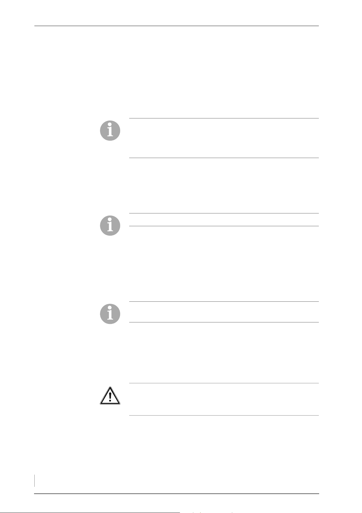
APPLICABLE REGULATIONS Local building regulations always apply. In Germany, individual state
regulations on boilers and furnaces also apply.
Building regulations may differ from country to country and state to
state.
For this reason, consult a qualified specialist for the planning and
installation of your boiler room.
Make sure there is an adequate supply of fresh air to the furnace
room so that there is enough air available for the combustion
process in all of the installed boilers, and to protect the operator from
the hazards of insufficient oxygen.
I
NSTALLATION A base is not necessary for installation of the boiler. Ensure alignment
on a horizontal plane.
Observe the fire safety regulations.
To ensure unhindered operation and maintenance of the heating
system, it is imperative that the heating system is installed in
accordance with the specifications of HDG Bavaria GmbH and that
the minimum spacing requirements are observed.
Also note that the thresholds in DIN 4109 “Soundproofing in building
construction” may not be exceeded.
More detailed information can be found in the relevant local and
national regulations.
Also observe the accident prevention regulations of the official
safety organisations.
We recommend that objects which are not needed for the operation
or maintenance of the heating system are not stored in the furnace
room.
REQUIRED ROOM SIZES AND MINIMUM CLEARANCES
Important!
When installing the pipes for the heating system, observe the
dimensions of the boiler and ensure the minimum clearances.
24
Page 25
4 Planning and installation – Structural requirements
Figure 4/2 - Required room sizes and minimum clearances
G
F
C
B
A
E
D
HDG F20/25/30 HDG F40/50
A at least 300 mm at least 300 mm
B at least 100 (or 600) mm at least 100 (or 600) mm
C at least 600 (or 100*) mm at least 600 (or 100*) mm
D 800 mm 800 mm
E 660 mm 760 mm
F at least 2200 mm at least 2300 mm
G at least 1400 mm at least 1500 mm
Minimum ceiling height 1900 mm 2000 mm
Recommended room height 2300 mm 2300 mm
min. installation dimensions
1025 x 650 x 1585 mm 1075 x 750 x 1645 mm
(without cladding and
attachments)
Table 4/2 - Room sizes and minimum clearances
*does not apply in connection with HDG automatic ignition system / automatic
cleaning system
25
Page 26

4 Planning and installation – Connections
4.3 Connections
CHIMNEY
According to EN 303-5, the entire flue system must be installed in
such a way that contamination, condensation and insufficient flue
draught are avoided. Here note that, in the accessible operational
area of the boiler, flue gas temperatures of less than 160 K above
room temperature may arise.
✎ The required flue gas values are listed in chapter “3 Mode of
operation”, section “3.3 Technical data”.
The benefits of the HDG F20-50 can only be enjoyed if all of the
prerequisites for good combustion are ensured. The heating system
and chimney form a single functional unit and must be adapted to
one another in order to guarantee fault-free and economical
operation.
Since the flue gas temperature may lie below 100°C when the system
is under partial load, a chimney/flue is required which meets the
requirements of DIN EN 13384-1: 2003-03 “Thermal and fluid
dynamic calculation methods”. If it does not meet this standard,
contact your specialist heating company or chimney technician.
When planning the flue system, a flue calculation based on DIN EN
13384-1 must be performed by authorised specialists.
Another essential criterion is meeting the flue draught requirement.
This depends on three major factors.
C
HIMNEY CHARACTERISTICS The requirements for minimising the draught loss in the chimney are:
• Good thermal insulation to avoid the flue gases cooling down too
quickly.
• Smooth interior surface to reduce the flow resistance.
• A tight seal of the chimney to avoid outside air leaking in. Air
penetrating from the outside speeds up the cooling of the flue
gases.
These requirements correspond to chimneys of the type conforming
to DIN EN 13384-1: 2003-03 “Thermal and fluid dynamic calculation
methods”.
Free-standing chimneys require particularly good insulation.
HIMNEY DIMENSIONS The system may only be connected to a chimney which has been
C
dimensioned in accordance with DIN EN 13384-1, taking into
account the fuel planned and the expected load, and which meets
local building regulations for the installation site.
26
A chimney can only be designed with full knowledge of the on-site
conditions. This includes taking into account the following factors:
• Building location
– Surrounding hills/slopes
– Wind direction
Page 27

4 Planning and installation – Connections
• Location of the chimney in the roof
2
A
B
1
– The opening of the chimney must be at least 0.5m above the
highest edge of roofs with a slope of more than 20° or at least
1.0 m higher than roof surfaces which slope at 20° or less.
• The effective height of a chimney is measured from the flue
entrance into it to the end of the chimney.
ONNECTING THE BOILER TO
C
THE CHIMNEY
The firing system must be connected with a connecting piece which
is as short as possible, at an angle which is less than 30 - 45° to the
chimney. You should aim for a connecting piece with a maximum
length of 1 m using just one fitting.
Every additional fitting results in a greater pressure loss in the
exhaust path and should thus be avoided. The same is true for overly
long connecting pieces. If, for constructional reasons, these must be
longer than 1 m, they should be adequately insulated (at least 5 cm
of mineral wool or equivalent material) and, if possible, fitted with an
upward inclination.
1 Auxiliary air unit
2Cleaning door
A) Chimney approx. 30° - 45°
B) Clearance at least 50 cm
Figure 4/3 - Chimney connection
The following should also be considered:
• The connecting piece may not protrude into the chimney.
• If the system flue gas pipe has a larger diameter than the chimney,
the connecting piece must reduce its diameter to that of the
connection. In this case, the connecting piece should taper as
gently as possible.
• Use bends rather than elbows; the radius of the elbow may not be
less than the diameter of the pipe.
• The chimney should be vertical and straight, if possible without
deformations (take particular care in older buildings).
• All of the cleaning doors and measurement hatches on the
chimney must have tight seals.
• To reduce the entry of additional cold air, only attach one heat
generator per chimney.
• To prevent dust from escaping, the flue pipe must be sealed with
heat-resistant silicone.
27
Page 28
4 Planning and installation – Connections
ELECTRICAL SYSTEM
The instructions in 2006/95/EC (low voltage directive) must be
followed for the electrical connections to the system. The electrical
connection must be made on a separate isolating unit.
✎ The required connection values are described in chapter “3 Mode
of operation”, section “3.3 Technical data”.
WATER
Important!
The heating system must be filled with water in accordance with
VDI guideline 2035, “Avoiding damage in hot water heating
systems”.
Antifreeze agents may only be used after prior consultation with
HDG.
USING AN ACCUMULATOR When calculating the thermal requirements of buildings, e.g.
according to DIN EN 12831 “Method for calculating the normal
heating load”, the lowest outside temperature of the relevant climate
zone (e.g. -15 °C) is used. These conditions only apply a few days per
year, thus, the thermal performance of the heating system is greater
than required on most days when heating is needed.
As the boiler for this system is rated for a nominal load, the use of an
accumulator is required.
The size of the accumulator must be adapted to the boiler type, the
type of wood and the building's heating requirements. In terms of 1.
BImSchV, the minimum capacity of the accumulator is 12 litres per
litre of fuel chamber capacity; however, the required 55 litres per kW
of nominal thermal power must be maintained.
For the HDG F20/25/30 boiler, the minimum accumulator volume is
2000 litres and for the HDG F40/50 it is 3000 litres.
Important!
Please also observe DIN EN 303-5 as well as the individual comfort
requirements of the customer for the capacity of the accumulator.
S
AFETY DEVICES Safety devices (e.g. boiler safety module, insufficient water cutout,
etc.) must be installed in accordance with DIN EN 12828: 2003
“Design of water-based heating systems in buildings”.
R
ETURN TEMPERATURE
CONTROL
Operating temperatures which are too low significantly shorten the
service life of the boiler. Water vapour contained in the flue gas could
be released in the form of condensation if the temperature drops
below the dew point (approx. 50 - 55 °C), especially in the area
28
Page 29

4 Planning and installation – Hydraulic connection
around the water-cooled heat-exchanger surfaces. This
condensation, in combination with combustion residue, can lead to
corrosion.
For these reasons, a return temperature control must be installed for
the HDG F20-50 heating system. The return temperature control
causes the water from the boiler return flow to be mixed with the
water from the boiler supply flow until the minimum return
temperature has been reached.
✎ The minimum return temperature is listed in chapter “3 Mode of
operation”, section “3.3 Technical data”.
The control of the return temperature is handled by the HDG controls
control unit.
The return temperature control consists of a 3-way mixing valve with
a 230 V servo drive (running time 120-240 s) and a circulation pump
from energy efficiency class A. For the HDG F20-50, we recommend
• Wilo 30/1-7.5, 3-way mixing valve DN 32 (or equivalent).
The pipe dimensions must be adapted to meet the requirements at
the site. Take the water-side connections of the boiler for the supply
and return into account.
✎ See chapter “3 Mode of operation”, section “3.3 Technical data”.
The return temperature control may not be further than 5 metres
from the boiler.
The hydraulic system must be installed in accordance with specific
technical principles of heating engineering. Take into account the
stop cocks required for maintenance work and repairs.
The return temperature control is not designed for the use of a
gravity brake and this should therefore not be installed.
The return temperature control must be installed according to the
specifications of HDG Bavaria.
4.4 Hydraulic connection
The hydraulic connection depends on the schematic diagram
selected in the respective HDG controls system.
✎ See the supplied schematic diagram and electrical circuit
diagram.
29
Page 30
4 Planning and installation – Scope of delivery
4.5 Scope of delivery
The boiler is delivered on a pallet. Included in the scope of delivery:
• Boiler HDG F20-50
• Cladding
• Cleaning tools
• Control unit HDG Control Touch
• Accessories
• Operating documentation
Important!
Upon delivery, small parts are located in the fuel chamber of the
HDG F20-50 boiler.
4.6 Installing the heating system
REQUIREMENTS
The heating system is installed by specialists from HDG Bavaria
GmbH or an authorised HDG partner and a qualified electrician.
Danger!
Risk of material damage and injury due to incorrect installation
Installing the system requires comprehensive specialist knowledge.
If installed by untrained persons, the heating system can be
damaged and persons may be injured due to secondary damage.
Only allow authorised specialists to perform the installation.
Danger!
Dangerous electrical current or voltage
Switch off the mains supply to the heating system during the
installation.
30
Page 31
4 Planning and installation – Installing the heating system
INSTALLING THE BOILER
1
2
2
3
1
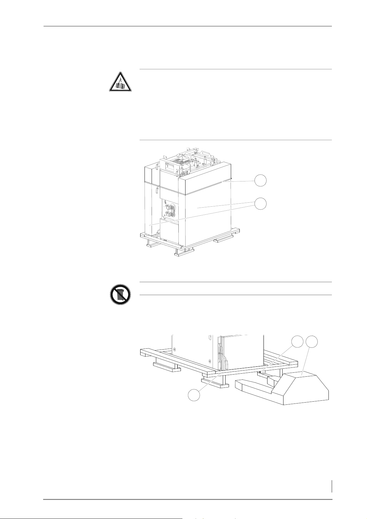
Caution!
Beware of suspended loads.
The boiler weighs over 650 kg. If the boiler is dropped during
transport, persons can be seriously injured and the boiler can be
damaged.
Make sure that you use appropriate lifting gear when placing the
boiler.
RANSPORTING WITH A PALLET
T
TRUCK
Figure 4/4 - Removing the cladding packages
1. Remove the packaging from the boiler.
The boiler packaging can be taken to the local recycling company.
2. Loosen the fastening strap (1) and lift the two side cladding
packages (2) away.
Figure 4/5 - Removing the pallet
3. Release the four M8 hexagon nuts (SW13) (2) under the boiler.
4. Remove the cross member from the pallet (1), from either the
front or rear of the boiler.
5. Slide the pallet truck (3) under the boiler.
6. Lift the boiler with a lifting truck (3).
31
Page 32
4 Planning and installation – Installing the heating system
T
2
3
1
1
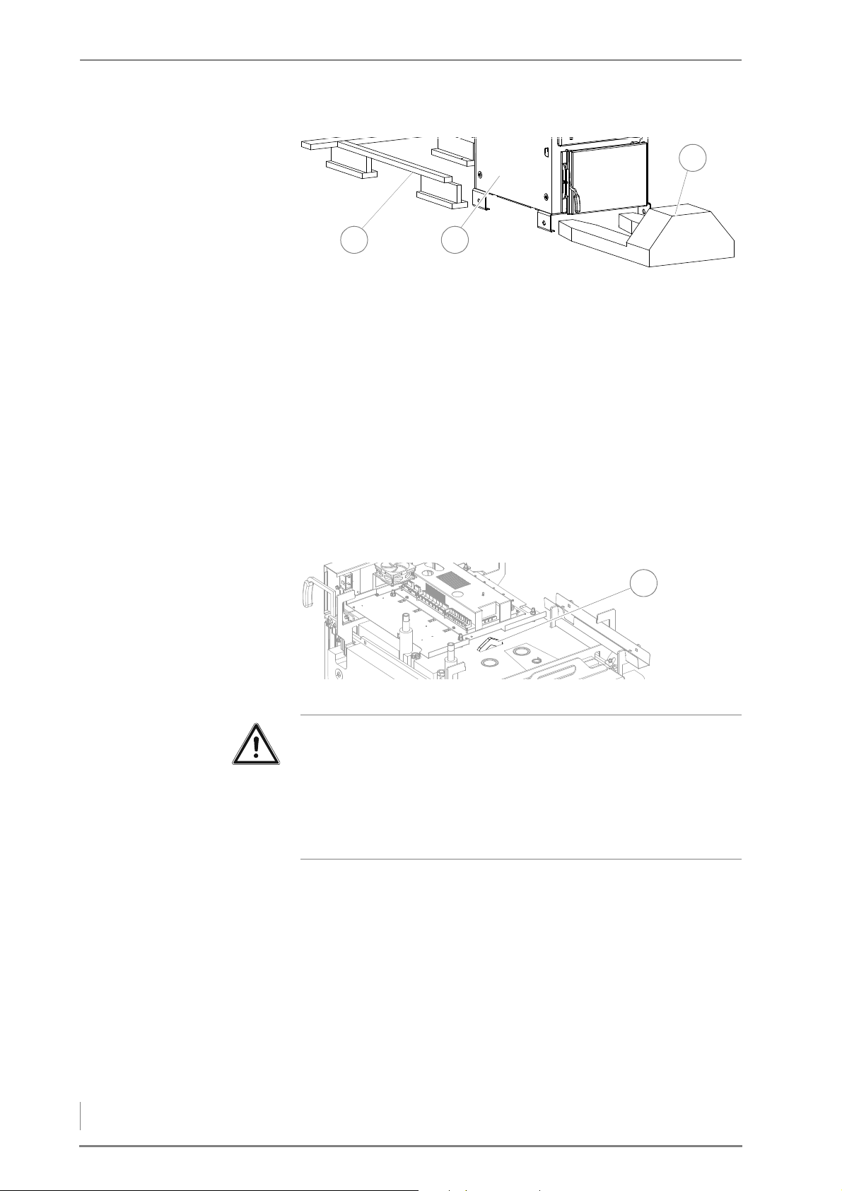
RANSPORT WITH A CRANE
Figure 4/6 - Transporting with a pallet truck
7. Pull the pallet (1) out from under the boiler (2).
8. Transport the boiler (2) to the desired installation site.
9. Set down the boiler (2) at the planned location while observing
the minimum clearances.
✎ See section “4.2 Structural requirements”, under “Required room
sizes and minimum clearances”.
10.Remove the lifting truck (3).
11.Align the boiler with plastic plates or flat steel strips (not included
in the scope of delivery) so that it is horizontal.
✓ The HDG F20-50 boiler has been placed in position.
Figure 4/7 - Crane eyelet
32
Warning!
Damage caused by improper assembly
The crane eyelet is located very close to the central module. It can
be damaged if the lifting equipment is not attached carefully.
When attaching the lifting equipment and during transport, ensure
that the central module is not damaged.
1. Attach suitable lifting equipment to the crane eyelet (1) provided
for this purpose.
✓ The boiler can now be moved with a crane.
2. Remove the transport pallet.
✎ See section "Transporting with a pallet truck".
3. Transport the boiler to the desired installation site.
4. Place the boiler at the planned location while observing the
minimum clearances.
Page 33
4 Planning and installation – Installing the heating system
HDG F20-50
2
1
3
4
✎ See section “4.2 Structural requirements”, under “Required room
sizes and minimum clearances”.
5. Align the boiler with plastic plates or flat steel strips (not included
in the scope of delivery) so that it is horizontal.
✓ The HDG F20-50 boiler has been placed in position.
INSTALLING HYDRAULIC CONNECTIONS
The following tasks must be performed if the HDG F20-50 is
configured only as a log wood boiler.
If the boiler is intended for combined use with a pellet unit, proceed
with section "HDG F20-50 Hybrid".
HDG F20-50 H
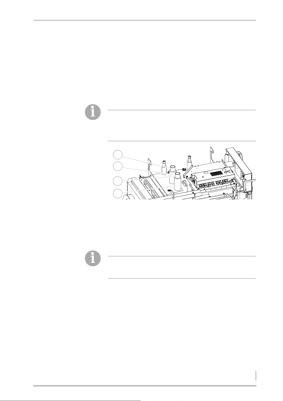
Figure 4/8 - Extending and insulating the connections
1. Extend the connection for the flow (1) and the return (3) using the
double pipe nipple supplied.
2. Insulate the connection extensions with the insulating hoses
supplied (2 + 4).
✓ The hydraulic connections are attached.
YBRID
The following tasks must be performed if the boiler is intended for
use as HDG F20-50 Hybrid in combination with an HDG K Hybrid
pellet unit.
33
Page 34
4 Planning and installation – Installing the heating system
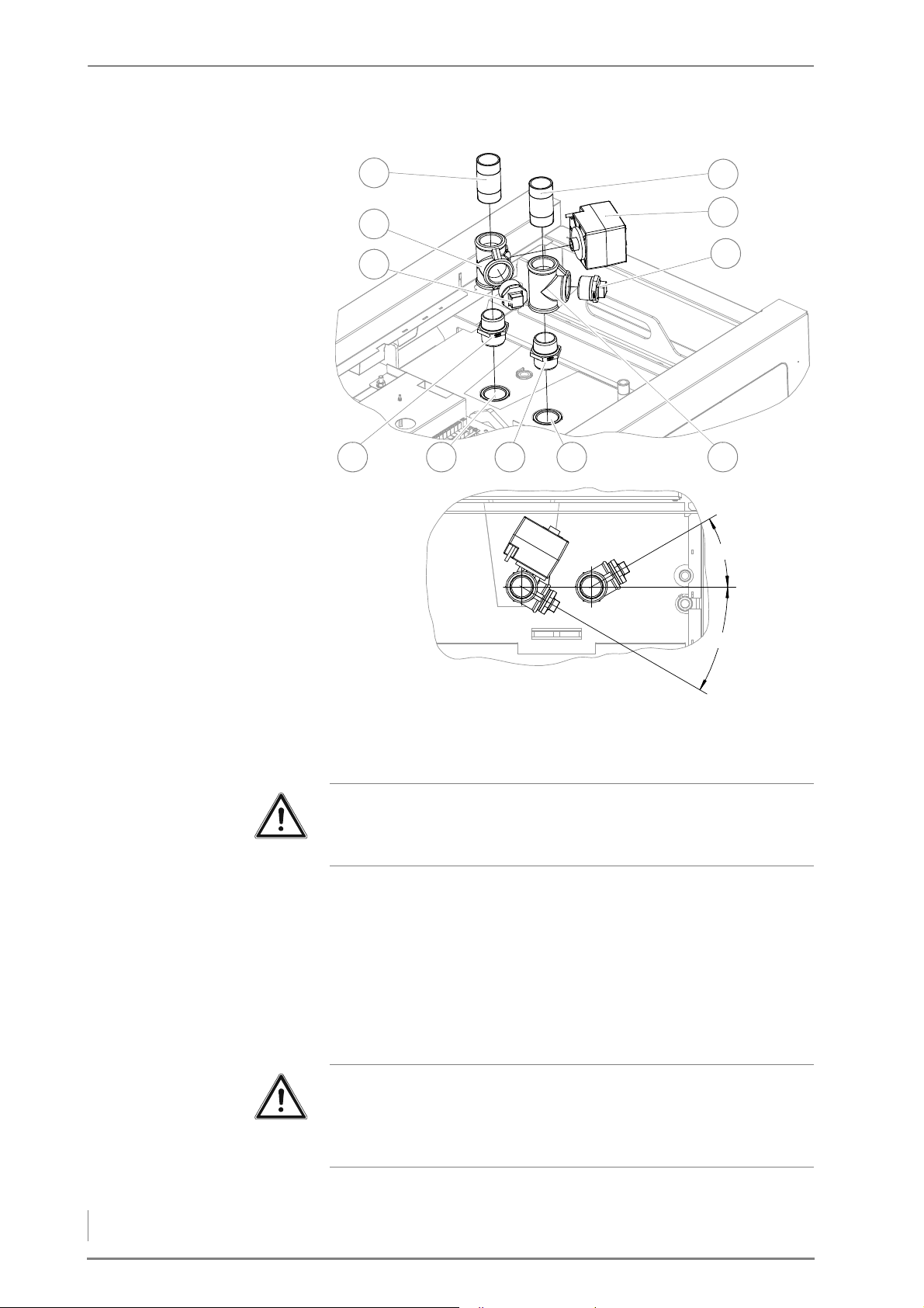
Figure 4/9 - Hydraulic connection set HDG F20-50 Hybrid
30°
30°
2
1
3
4
9
865 7
10
11
1. Mount the double nipple (4 + 6) on the connection for the flow (7)
or the return (5).
Important!
When installing the three-way switch valve (2) and the T-piece (8),
ensure the proper installation angle!
2. Install the three-way switch valve (2) on the double nipple (4).
3. Install the actuator (10) on the three-way switching valve (2) using
the fastening screw.
4. Run the cable from the actuator (10) to the central module and
insert the connector in the central module.
✎ See “Electrical plans for the HDG log wood boiler”.
5. Install the T-piece (8) on the double nipple (6).
Important!
If the pellet unit will be retrofitted at a later point in time, dummy
plugs must be installed on the three-way switching valve (2) or Tpiece (8).
34
Page 35
4 Planning and installation – Installing the heating system
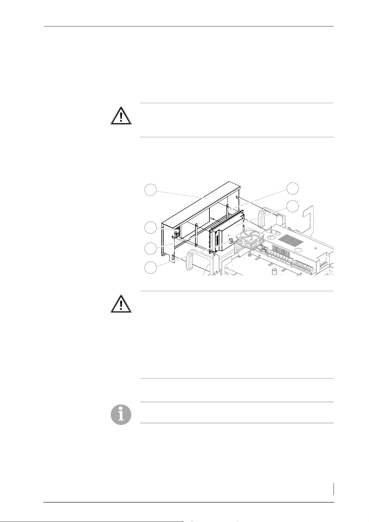
INSTALLING THE CONTROL UNIT
2
1
4
6
5
3
6. Install the dummy plugs (3 + 9) on the three-way switching valve
(2) or T-piece (2).
7. Install the pipe double nipple (1 + 11) on the three-way switching
valve (2) or T-piece (2).
✓ The hydraulic connections are attached.
Important!
✎ For the further installation of the log wood/pellet combination
HDG FK Hybrid, see the "HDG K hybrid operating manual".
INSTALLING THE HDG CONTROLS CONTROL UNIT
Figure 4/10 - Installing the control unit
Important!
Damage caused by improper disassembly
The overheat cut-off device (2) is already pre-mounted on the
support plate (1), the line connected and the capillary tube of the
overheat cut-off device sensor installed. When removing the
support plate, the overheat cut-off device or the capillary tube may
be damaged.
During disassembly of the support plate, ensure that the overheat
cut-off device and the capillary tube are not damaged.
1. Undo the four lateral M5 screws (SW8) and carefully lift the
support plate (1) out of the holder.
The two spacer plates are packed and delivered in cladding
package 1.
2. From behind, set the two spacer plates (3 + 6) onto the welded
screws on the support plate (1).
3. Move the HDG Control Touch control unit (5) from behind to the
welded screws on the support plate (1).
4. Fasten the HDG Control Touch control unit (5) on the support
plate (1) with the M4 nut (SW7).
35
Page 36
4 Planning and installation – Installing the heating system
F
1
2
3
LOW/RETURN AND STL
SENSORS
E
XTENSION MODULE
I
NSTALLING EXTENSION
MODULE EM4
5. Plug the connection cable (4) on the control unit HDG Control
Touch (5) at slot X3.
✎ Also refer to “Electrical plans for the HDG log wood boiler”.
6. Mount the support plate (1) in the reverse sequence.
The flow/return and STL sensors are already installed upon delivery.
Depending on the hydraulic application, an EM4 extension module
may have to be used.
Important!
If the EM4 extension module is used, this must be installed on the
top next to the central module. If extension module EM8 or EM8+4
is used alternatively or in addition, it must be installed on the
external housing outside the boiler.
✎ For connecting the extension module, see the “Electrical plans
for the HDG log wood boiler”.
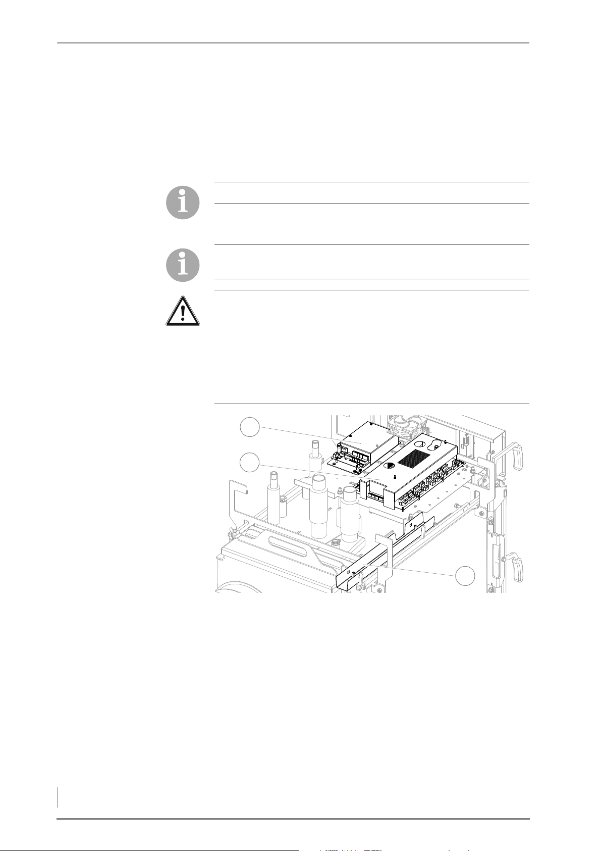
Figure 4/11 - Installing the EM4 extension module
1. Install the EM4 extension module (1) next to the central module
2. Connect the EM4 (1) extension module.
✎ See “Electrical plans for the HDG log wood boiler”.
3. Install the cables and sensors on extension module EM4 according
✓ Extension module EM4 is installed.
36
(2).
to the hydraulic wiring diagram.
Page 37
4 Planning and installation – Installing the heating system
CONNECTING THE CABLES
1
3
2
4
Caution!
Malfunctions due to incorrect cabling
If live cables and sensor cables are installed in the same ducts, it can
cause the sensors to malfunction.
Ensure that the live wires and the sensor cables are installed in
different cable ducts (3).
1. Route all the cables and sensors to the central module and any
extension module(s).
2. Connect all the cables on the central unit and any extension
module(s).
✎ See “Electrical plans for the HDG log wood boiler”.
Please note that here only the assembly of the HDG controls unit is
described.
The remaining electrical installations depend on the hydraulic
system and can be installed based on the specifications for the
respectively selected system.
✓ The HDG controls unit is now installed.
INSTALLING THE AUTOMATIC IGNITION
The HDG automatic ignition is available as an option and not
included in the standard scope of delivery.
Important!
Below, installation of the automatic ignition system is described on
the right boiler side. Installation on the left side of the boiler is
analogous.
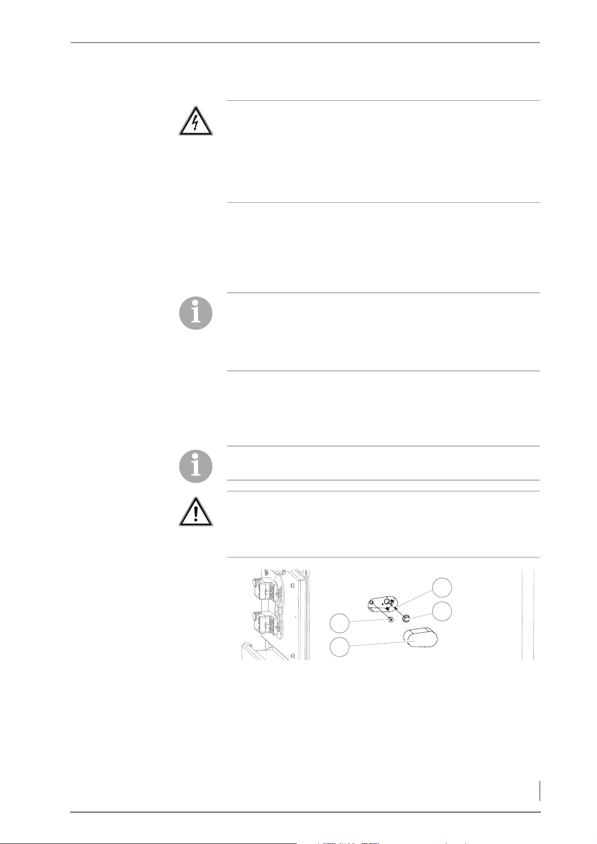
Figure 4/12 - Dismantling the cladding and dummy plugs
1. Remove the perforated insulation (2).
2. Remove the M8 hexagon socket screws (SW6) (1).
3. Tighten the three M5 hexagon socket screws (SW4) (4).
4. Remove the dummy plugs (square SW13) (3).
37
Page 38
4 Planning and installation – Installing the heating system
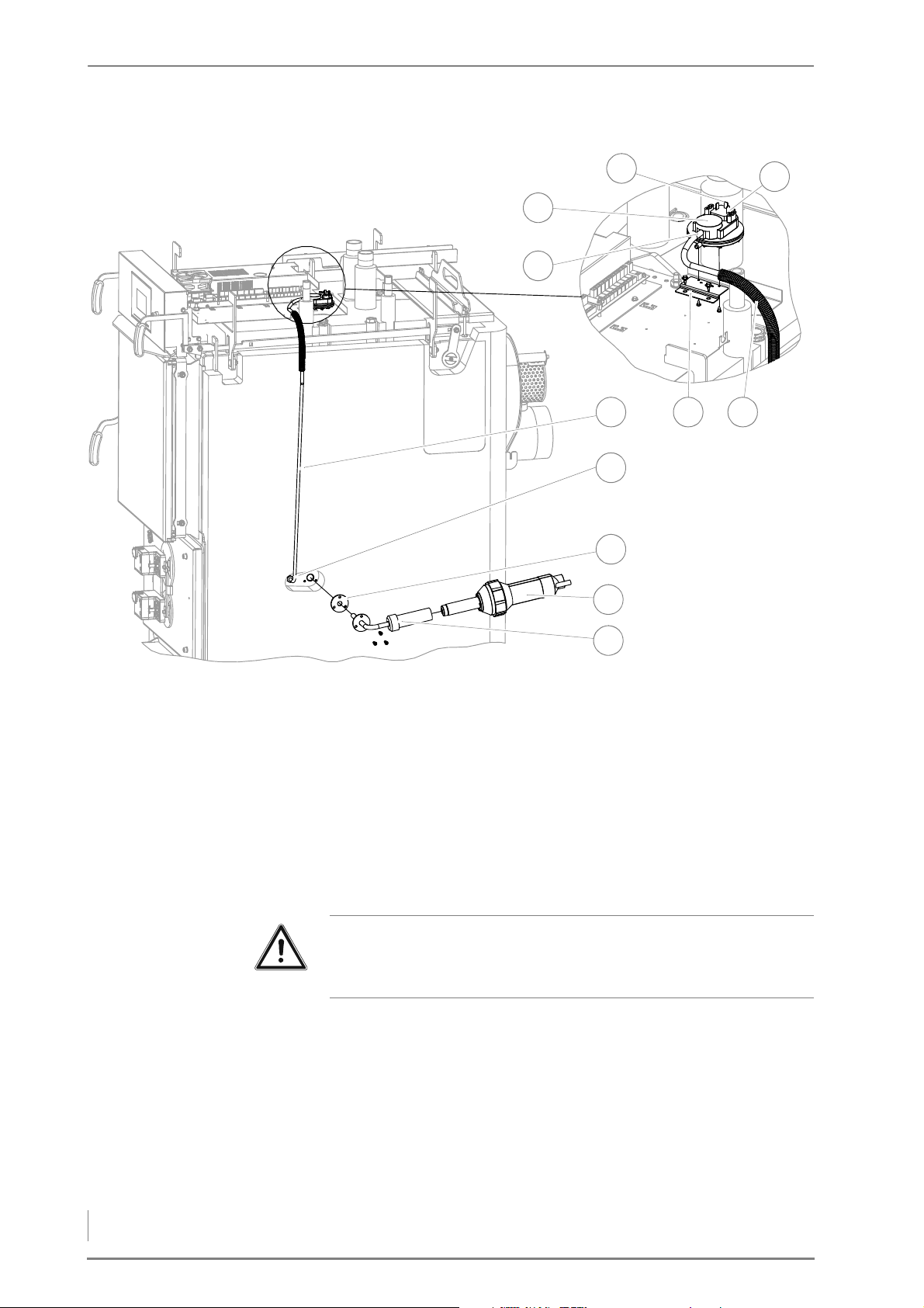
Figure 4/13 - Installing the differential pressure switch and ignition fan
6
1
2
3
7
8
11
9
4
5
10
5. Install the ignition pipe (11) with the seal (9) placed in between
with the M5 hexagon socket screws (SW4) onto the connection
provided on the boiler.
6. Mount the differential pressure switch (3) with the two self-
tapping screws on the retaining plate (6).
7. Mount the retaining plate (6) with the two drilling screws (SW5,5)
on the assembly plate.
8. Screw the hose nozzle (SW14) (8) into the connection for the
differential pressure switch on the boiler.
Important!
Make sure that the silicone hose is fitted so that it does not come
into contact with the ignition pipe.
9. Slide the empty pipe (5) in the area of the cleaning system lever
over the silicone hose (7).
10.Insert the silicone hose (7) on the hose nozzle (8) and on the top
connection on the differential pressure switch (4).
11.Insert the flat plug receptacle of the brown wire from the cable for
the differential pressure switch into socket 1 (1).
12.Insert the flat plug receptacle of the white wire from the cable for
38
the differential pressure switch into socket 3 (2).
Page 39
4 Planning and installation – Installing the heating system
13.Run the cable from the differential pressure switch (2) to the
1
2
3
central module and plug it in at slot X34.
✎ Also refer to “Electrical plans for the HDG log wood boiler”.
14.Push the ignition fan (10) into the ignition pipe (11).
Important!
Make sure that the line from the ignition fan is fitted so that it does
not come into contact with the ignition pipe.
15.Run the cable from the ignition fan (10) to the central module and
plug it in at slot X52.
✎ Also refer to “Electrical plans for the HDG log wood boiler”.
✓ The automatic ignition is now installed.
INSTALLING THE AUTOMATIC CLEANING SYSTEM
The HDG automatic cleaning system is available as an option and
not included in the standard scope of delivery.
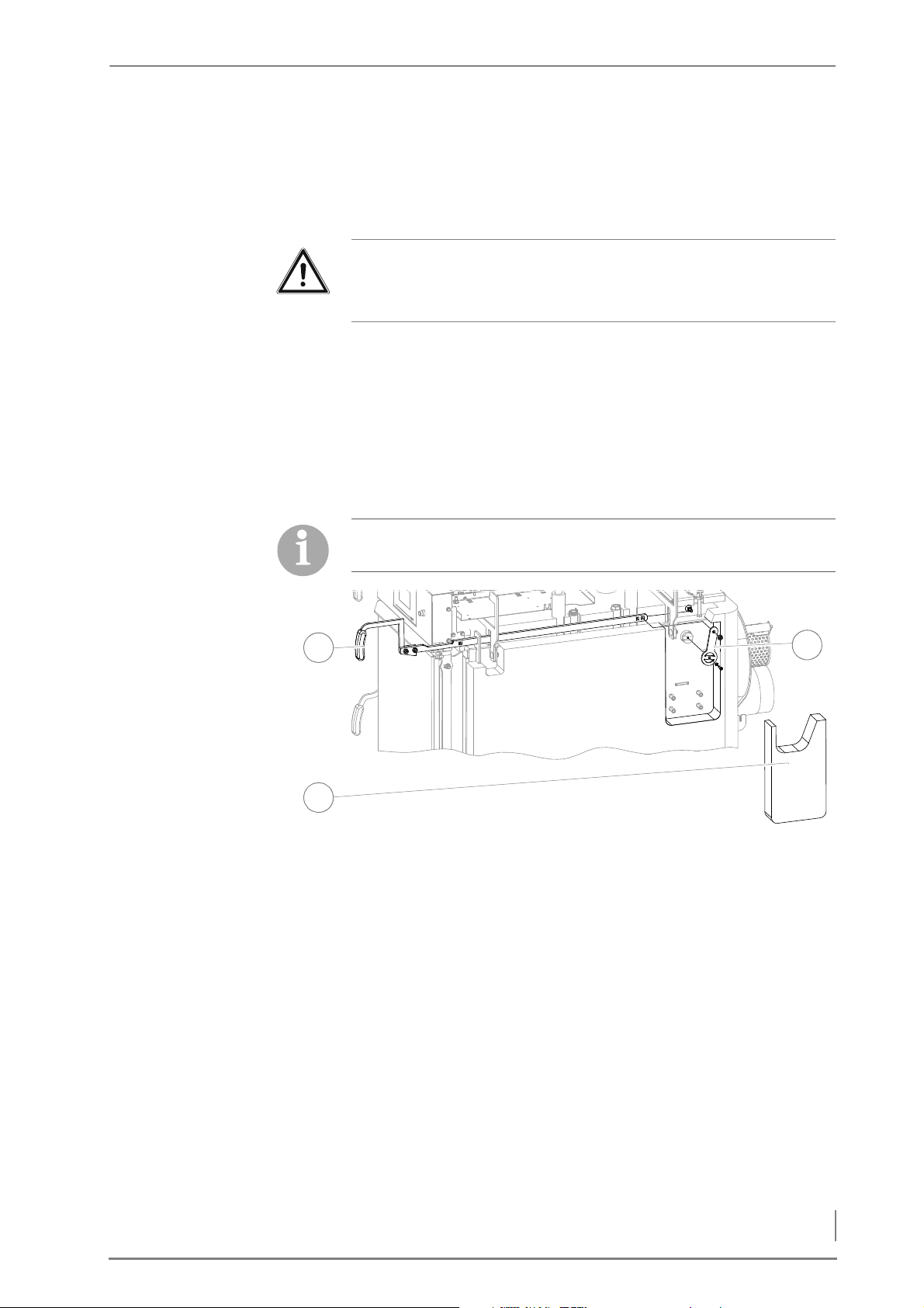
Figure 4/14 - Dismantling the cleaning system lever
1. Unscrew the M8 nut (SW13) and pull the actuating lever (1) of the
cleaning system forward.
2. Unscrew the M5 hexagon socket screws SW4 and remove the
small lever (3).
3. Remove the perforated insulation (2).
39
Page 40
4 Planning and installation – Installing the heating system
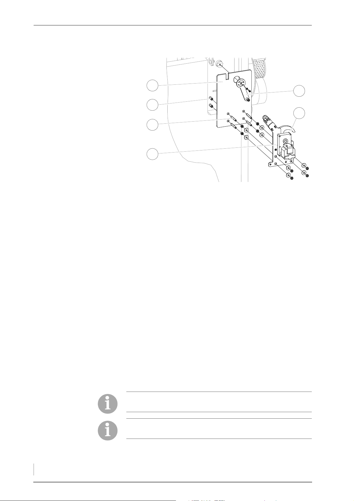
Figure 4/15 - Installing the cleaning system motor
1
3
6
4
2
5
4. Move the ceramic fibre plate (1) over the long nuts (2) to the
boiler.
5. Install the small lever (6) with the M5 hexagon socket screws (SW4)
and spring ring on the cleaning shaft.
6. Screw the M8 threaded pin (3) into the long nuts (2).
7. Screw the M8 nuts (SW13) onto the threaded pin (3).
8. Set the washers onto the threaded pin (3).
9. Install the support plate (4) for the cleaning system motor and the
limit switch with the M8 screws (SW13) and the washers on the
threaded pin (3).
10.With the help of the M8 nuts (SW13), set the spacing of the
support plate (4) so that the hook (5) runs centred on the roller of
the lever (6).
11.Run the cable from the cleaning system motor and from the limit
switch to the central module and insert it at slot x50 or X33.
✎ Also refer to “Electrical plans for the HDG log wood boiler”.
✓ The automatic cleaning system is now installed.
FITTING THE CLADDING
The cladding should only be installed after the water and flue-gas
piping and electrical wiring.
The cladding packets are numbered chronologically. The number
also corresponds to the order in which the cladding part is needed.
40
Page 41
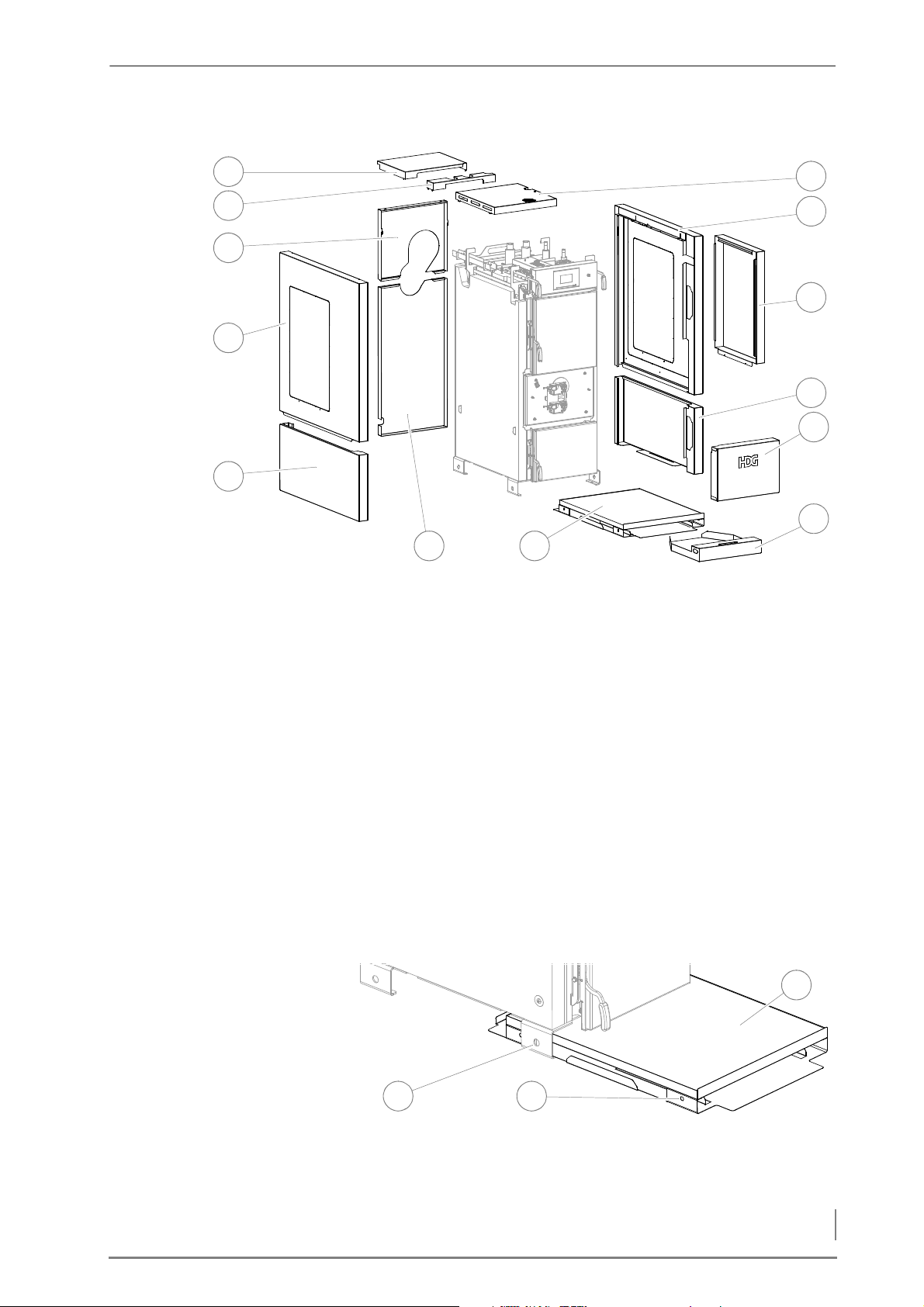
4 Planning and installation – Installing the heating system
3
4
1
2
5
6 7
8
9
10
12
13
11
2
3
1
B
ASE PLATE
Figure 4/16 - Overview of cladding parts
1 Top rear cover
2 Top centre cover
3 Top rear cladding
4 Top left side cladding
5 Bottom left side cladding
6 Bottom rear cladding
7 Base plate
8Ash pan
9 Front cladding
10 Bottom right side cladding
11 Automatic ignition/cleaning system cover (optional)
12 Top right side cladding
13 Top front cover
Figure 4/17 - Sliding in the base plate
1. Slide the base plate (3) under the boiler until the holes (3) in the
base plate overlap into the recesses (1) in the base.
41
Page 42
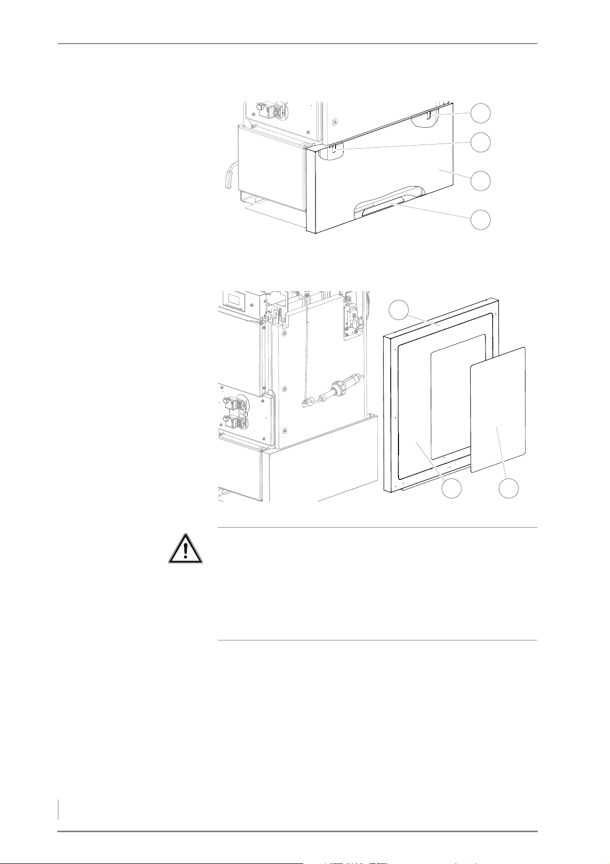
4 Planning and installation – Installing the heating system
SIDE CLADDING
3
2
4
1
1
32
Figure 4/18 - Fitting the lower side cladding
2. Hang the lower side cladding (4) with the recess in the base plate
(3) and in the two bottom cladding brackets (1 + 2).
42
Figure 4/19 - Fitting the upper side cladding
Important!
The small perforated recess (3) only needs to be cleared out if the
boiler is equipped with the HDG automatic ignition system and/or
HDG automatic cleaning system.
The large perforated recess (2) only needs to be cleared out if the
boiler is configured as HDG F Hybrid for combined use with a HDG
K Hybrid pellet unit.
3. If necessary, clear out the small perforated recess (3) from the right
side cladding (1) using a side cutter or hacksaw and deburr the
opening.
Page 43
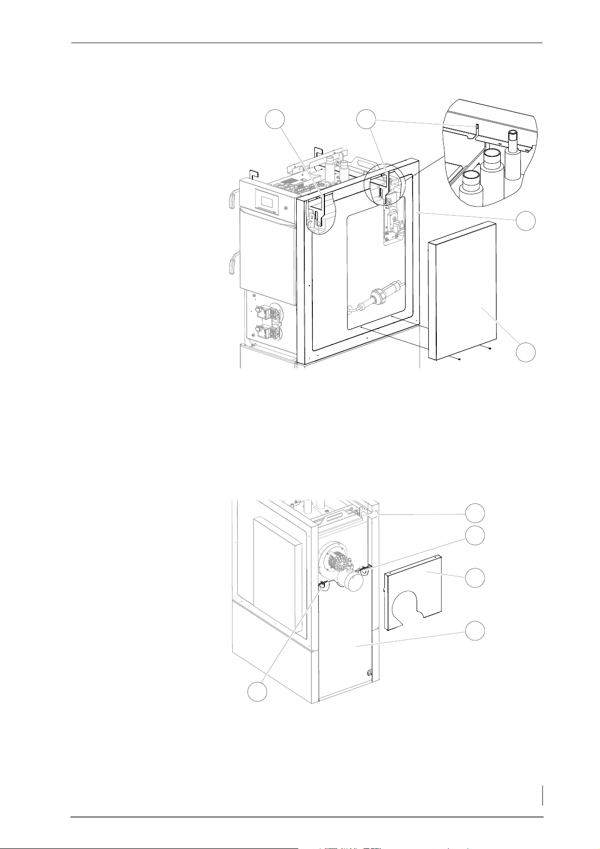
4 Planning and installation – Installing the heating system
EAR CLADDING
1
5
4
2
3
2
4
5
1
R
Figure 4/20 - Fitting the upper side cladding
4. Hang the upper side cladding (4) into the lower side cladding and
into the two upper cladding brackets (1 + 2).
5. If necessary, hang the side cover (5) into the side cladding (4) and
fasten it at the bottom with the two drilling screws.
6. Proceed in the same manner described above for fitting the
cladding on the left side.
Figure 4/21 - Installing the rear cladding
7. Hang the lower rear cladding (4) into the base plate and into the
two bottom cladding brackets (2 + 5).
43
Page 44
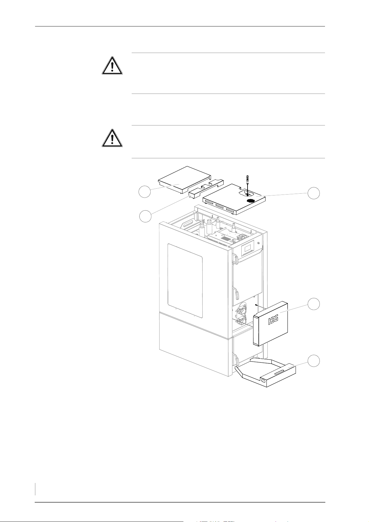
4 Planning and installation – Installing the heating system
T
1
2
3
4
5
OP AND FRONT CLADDING
Important!
Make sure that the cables for the flue gas fan, the lambda sensor
and the flue gas temperature sensor are routed outside the rear
cladding to the recess (1) in the side cladding.
8. Place the upper rear cladding (3) into the lower rear cladding and
hang it into the two side claddings with the tabs.
Important!
The supper covers should only be mounted once all lnes and
sensors have been installed and connected.
Figure 4/22 - Installing the top and front cladding
9. Put the top rear cover (1) with the tabs into the recesses of the left
and right hand side cladding.
10.Put the top middle cover (2) with the tabs into the recesses of the
left and right hand side cladding.
11.Put the top front cover (3) with the tabs into the recesses of the left
and right hand side cladding and lock it with a flathead
screwdriver.
44
Page 45

4 Planning and installation – Connecting the chimney
12.Put the front cladding (4) onto the nipple on the boiler and ensure
that the lines for the primary or secondary air actuator are led out
through the recess on the top left.
13.Slide the ash pan (5) under the boiler in the base plate.
✓ The cladding is installed.
4.7 Connecting the chimney
1. Connect the flue gas pipe to the chimney connection.
2. Make sure that the connecting piece does not protrude into the
chimney.
3. Seal the connection to the chimney with highly fireproof silicone
or with a suitable mortar.
✓ The boiler is now connected to the chimney.
4.8 Electrical system
The electrical connections must be made in accordance with DIN IEC
60364 “Setting up low-voltage electrical installations”.
4.9 Water
✎ The technical details are described in chapter “3 Mode of
operation”, section “3.3 Technical data”.
✎ The circuit diagram is enclosed with the supplied documentation.
This is created based on the system selected.
Important!
The heating system must be filled with water in accordance with
VDI guideline 2035, “Avoiding damage in hot water heating
systems”.
Before putting the system into operation, the pressure of the
diaphragm expansion vessel must be adjusted for the conditions in
the heating system and in the building.
After putting the system into operation, heat up the system to the
maximum boiler temperature and bleed air from the system again to
make sure that there are no air pockets.
45
Page 46
4 Planning and installation – Connecting the thermal safety device
4.10 Connecting the thermal safety device
In accordance with DIN EN 12828, heating systems must be
equipped with safety devices to prevent the maximum operating
temperature from being exceeded. The safety heat exchanger serves
to protect the boiler against overheating and may not be used for
other purposes (i.e. as a regular heat exchanger). If the heat transfer
capacity is suddenly lost (for example, if the circulation pump for
raising the return temperature fails), heat production cannot be
stopped as quickly as with an oil- or gas-fired boiler. When the
maximum operating temperature is exceeded, the thermal safety
device (TAS) is triggered and cold water flows through the safety
heat exchanger. The resulting excess energy is thus dissipated by this
“emergency cooling”. (This is an alternative to fast regulation.)
However, the safety heat exchanger and thermal safety device can
only serve their purpose if the following requirements have been
met:
• A flow pressure of at least two bar must be available at the cold
water inlet of the safety heat exchanger.
Mains-dependent, stand-alone supply systems are not safe enough
due to dependence upon the power supply!
• The distance between the supply and return lines of the thermal
safety device and the safety heat exchanger should not be less
than their nominal width. The supply line may not be equipped
with a shut-off valve.
• Water must be able to flow freely through the system.
• The flow pressure at the flue pipe connection on the boiler may
not significantly exceed the prescribed value.
The TAS must be inspected annually by a qualified technician to test
that it is working properly.
The thermal safety device must be installed according to guidelines
from HDG Bavaria.
Important!
In order to prevent leaks, avoid turning the connections of the
safety heat exchanger anticlockwise when installing the thermal
safety device.
46
Page 47
4 Planning and installation – Connecting the thermal safety device
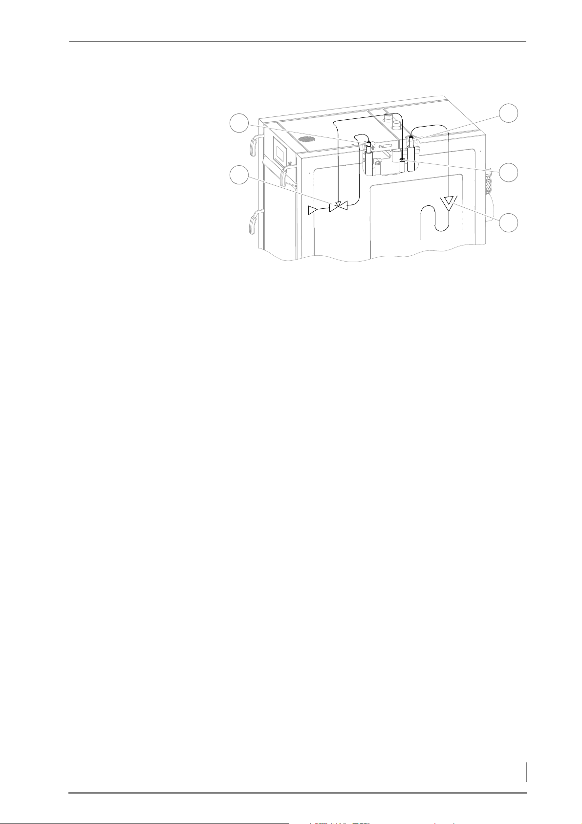
Figure 4/23 - HDG F20-50 thermal safety device
2
1
5
4
3
1 Safety heat exchanger inlet (DN 15 outsize thread)
2 Thermal safety device (TAS)
3 Safety heat exchanger outlet (DN 15 outside thread)
4 Connection bushing for TAS immersion sleeve, DN 15 inside
thread
5 Runoff connection to drainage system
47
Page 48

5 Commissioning – Requirements
5 Commissioning
The heating system is initially commissioned by specialists from HDG
Bavaria or from an authorised HDG partner.
Commissioning includes an introduction to the operation and
maintenance of the heating system as well as measurements to
determine exhaust emissions and combustion performance.
Danger!
Material damage and injury due to incorrect commissioning
Commissioning the system requires comprehensive expertise. If
this commissioning is done by an untrained person, the heating
system could be damaged.
Only allow authorised specialists to perform the commissioning.
5.1 Requirements
The following requirements must be met to ensure there are no
problems during commissioning.
5.2 Procedure
• The boiler is installed properly.
• The heating system has been filled with water as specified.
• The heating system has been bled.
• The pressure of the membrane expansion vessel has been
adapted to on-site conditions.
• All required DIN EN 12828 safety devices have been installed and
are ready for operation.
• The power supply to all components is ensured. (Makeshift
solutions are not sufficient!)
• The chimney installation corresponds to the legal regulations.
• All doors and openings on the boiler and on the chimney
connection pipe have been checked for a proper seal.
• Air supply for combustion has been provided.
• A sufficient amount of fuel is available.
✎ See the “HDG Control” operating manual, chapter
“Commissioning the system”.
48
Page 49
5 Commissioning – Procedure
SWITCHING ON THE HEATING SYSTEM
1. Switch on the circuit breaker for the mains electricity supply, or
otherwise ensure the unit is provided with power.
2. Turn on the emergency heating switch (if one has been installed).
✓ The heating system is now under voltage.
✓ The indicator lamp in the emergency heating switch will light up.
✓ The control is activated.
✎ See the “HDG Control” operating manual, chapter
“Commissioning the system”.
TESTING SYSTEM COMPONENTS
Important!
For safety reasons, the system component test may only be
conducted when there is no fuel in the boiler and there are no
remaining embers.
The system component test can only be conducted in the “Boiler
OFF” state.
PROCEDURE ✎ See the “HDG Control” operating manual.
Depending on the hydraulic system selected, the system
component test must be performed for additional components.
49
Page 50
6 Using the heating system – Control unit for HDG controls
6 Using the heating system
6.1 Control unit for HDG controls
✎ You can find all information and instructions for setting up and
operating the boiler and weather-compensated heating control
of the HDG controls in the “HDG controls” operating manual.
The HDG controls control unit is located on the front of the HDG F2050 boiler.
6.2 Switching on the heating system
REQUIREMENTS
✎ See the “HDG Control” operating manual, chapter
“Commissioning the system”.
In order for the heating system to be switched on, it must first have
been put into service by an authorised specialist.
EMERGENCY HEATING SWITCH
The system is connected to the mains supply through an emergency
heating switch (provided by the customer) or through a circuit
breaker in the mains distribution box of the building.
Danger!
Dangerous electrical current or voltage
The heating system can only be completely de-energised by
switching off the mains circuit breaker or the emergency heating
switch.
1. Switch on the heating system at the corresponding circuit breaker
or the emergency heating switch provided by the customer.
✓ The heating system is now under voltage.
✓ The control is activated.
✓ The heating system is switched on and ready for operation.
50
Page 51
6 Using the heating system – Heating up the system
FUEL SELECTION
Important!
When changing fuel, e.g. from softwood to hardwood, please also
consider the consequential changes in respect of the combustion
properties. Otherwise faults may occur in the combustion and in
the operation of the heating system.
If necessary, the settings of the heating system must be adjusted for
the changed fuel.
6.3 Heating up the system
GENERAL INFORMATION
Caution!
Hot surfaces
Contact with the hot surfaces of the boiler (e.g. inside doors) can
result in burns.
Wait until the boiler has cooled down before touching noninsulated components.
Warning!
Danger of asphyxiation due to carbon monoxide
If the boiler is operating, carbon monoxide can be emitted through
open doors.
Do not leave the doors open any longer than necessary.
Caution!
Danger of fire
When the boiler is in operation, open doors constitute a fire danger.
Do not leave doors open any longer than necessary and never leave
them open unattended. Check that the hatches are closed every
time you heat or reload.
Danger!
Danger of explosion
A concentration of carbon monoxide that is too high can result in
an explosion.
Observe the flue draught requirement of the chimney.
51
Page 52
6 Using the heating system – Heating up the system
REQUIREMENTS
1
2
1
We recommend wearing leather gloves when heating up the
system.
Caution!
Damage caused by unintended fuel fomentation
Residual embers in the fuel chamber can lead to unintended fuel
fomentation. This can cause the heating system to overheat and,
subsequently, for dangerous operating conditions to arise.
Ensure when filling that residual embers do not under any
circumstances remain in the fuel chamber.
When the Reload indicator lights up, there are no more embers in the
fuel chamber.
PROCEDURE
1. Pull the actuating handle (1)
of the cleaning system 4-5
times to clean the upright
heat exchangers.
Figure 6/1 - Cleaning system actuation
2. Press the Reload button on the HDG Control Touch control unit (2).
✓ The Fill up / Reload window appears in the display.
Figure 6/2 - Ignition - changing settings
3. If you do not want to change any settings, confirm your input by
pressing the Confirm button (1).
✓ The Do not open fuel chamber door message appears in the display.
✓ The flue gas fan is running.
4. Continue without changing the settings with point 18.
52
Page 53
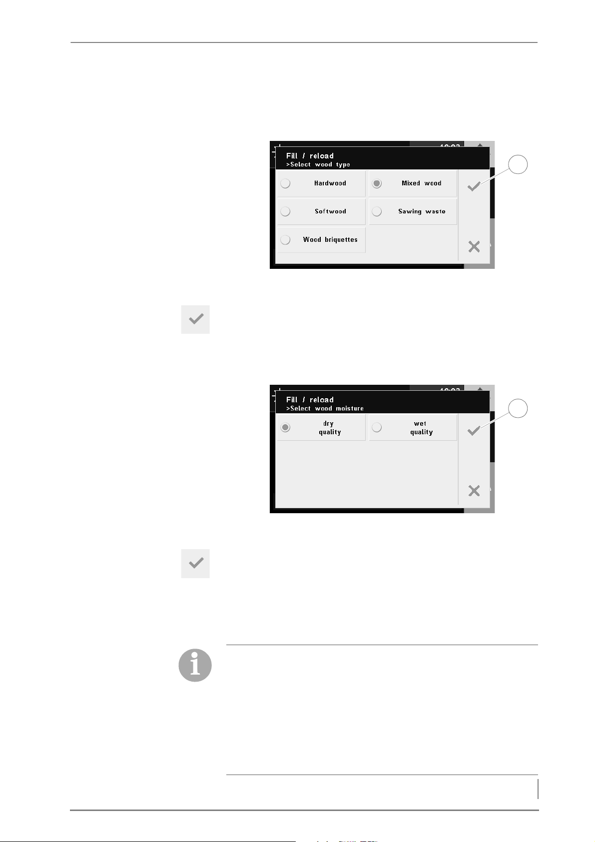
6 Using the heating system – Heating up the system
CHANGING THE SETTINGS 5. If you wish to change the settings, press the appropriate setting.
1
1
6. Press the Wood type.
✓ The Wood type selection window appears in the display.
Figure 6/3 - Query wood type
7. Select the type of wood used.
8. Confirm your input by pressing the Confirm button (1).
✓ The Fill up / Reload window appears in the display again.
9. Press Wood moisture.
✓ The Wood moisture selection window appears in the display.
Figure 6/4 - Query wood moisture
10.Select the wood moisture of the fuel.
11.Confirm your input by pressing the Confirm button (1).
✓ The Fill up / Reload window appears in the display again.
12.Press the Ignition mode.
✓ The Ignition mode selection window appears in the display.
Ignition modes
• Manual: The fuel is ignited manually (with firelighters).
• Electrical: The fuel is automatically ignited by the ignition fan
directly after filling, regardless of the accumulator temperature,
weekly programme or consumer requirement.
• Automatic: The fuel is automatically ignited depending on the
selected setting (accumulator temperature, weekly programme
or consumer requirement)
53
Page 54
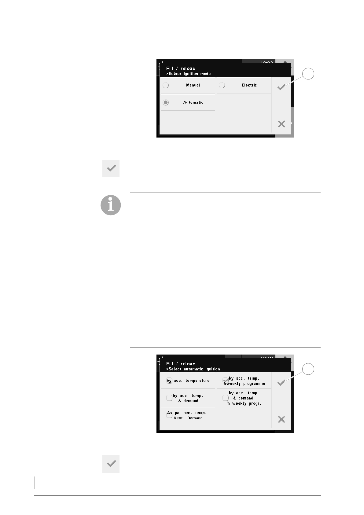
6 Using the heating system – Heating up the system
Figure 6/5 - Query ignition mode
1
1
13.Select the desired ignition mode.
14.Confirm your input by pressing the Confirm button (1).
✓ The display shows - for prior selection of Automatic ignition mode
- the Automatic ignition selection window.
Automatic ignition
• Accumulator temperature: The automatic ignition starts after
the set reloading temperature is undershot.
• Accumulator temperature and weekly programme: The
automatic ignition starts after the set accumulator temperature
is undershot and if the enable time is reached at the same time
in accordance with the set weekly programme.
• Accumulator temperature and requirement: The automatic
ignition starts after the set accumulator temperature is
undershot and if there is a requirement from a consumer
(heating circuits, domestic hot water) at the same time.
• Accumulator temperature, requirement and weekly
programme: The automatic ignition starts after the set
accumulator temperature is undershot and if there is a
requirement from a consumer (heating circuits, domestic hot
water) at the same time and the enable time is reached in
accordance with the set weekly programme.
54
Figure 6/6 - Query automatic ignition
15.Select the type of automatic ignition.
16.Confirm your input by pressing the Confirm button (1).
✓ The Fill up / Reload window appears in the display again.
Page 55
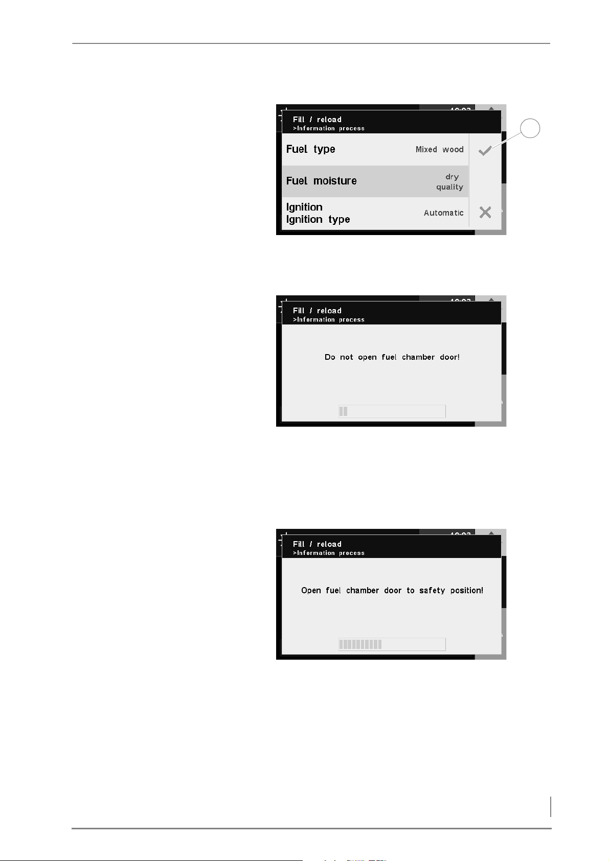
6 Using the heating system – Heating up the system
D
1
O NOT CHANGE THE SETTINGS
ÄNDERN
Figure 6/7 - Ignition - changing settings
17.Confirm your input by pressing the Confirm button (1).
✓ The Do not open fuel chamber door message appears in the display.
Figure 6/8 - Do not open the fuel chamber door
✓ The flue gas fan is running.
18.Wait until the progress bar is full.
✓ The Open fuel chamber door to safety position message appears in
the display.
Figure 6/9 - Opening the fuel chamber door to the safety position
19.Open the fuel chamber door to the safety position.
20.Wait until the progress bar is full.
✓ The Open fuel chamber door slowly message appears in the display.
55
Page 56
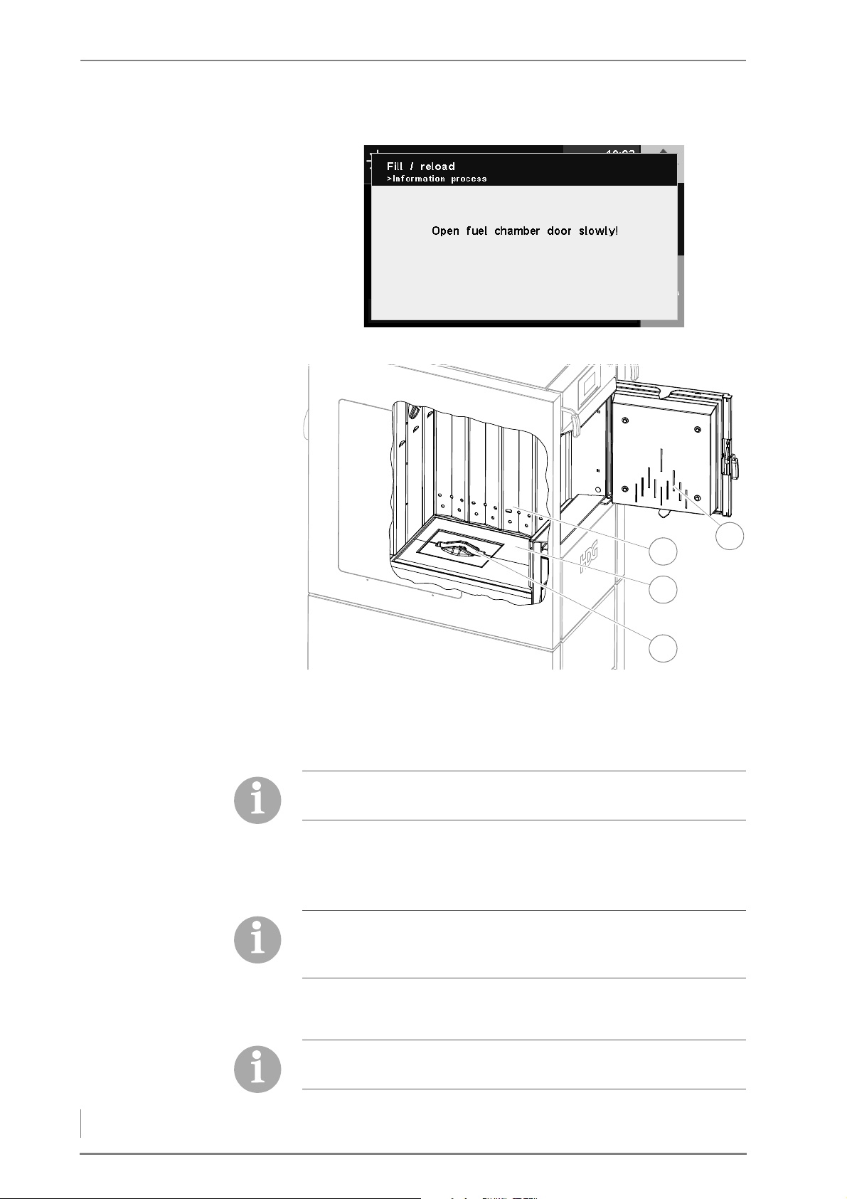
6 Using the heating system – Heating up the system
Figure 6/10 - Open the fuel chamber door slowly
3
1
4
2
Figure 6/11 - Filling the fuel chamber
21.Open the fuel chamber door (1).
22.Leave any unburnt pieces of wood and charcoal in the fuel
chamber (3).
ANUAL IGNITION 23.Stack some highly flammable material (small pieces of dry wood)
M
56
For kindling, we recommend log wood with a diameter of D5 (2–5
cm).
about 10 cm high on the burner nozzle (4) so that it is covered.
24.Lay some small pieces of cardboard on top of the wood inside the
fuel chamber (3).
We recommend using bio-firelighters consisting of wood shavings
soaked in paraffin. In contrast to newsprint, these firelighters are
smokeless, odourless and free of pollutants.
25.Ignite the fuel.
26.Allow the fuel to generate a good fire.
Only put in as much wood as the heating system and accumulator
can absorb as energy.
Page 57
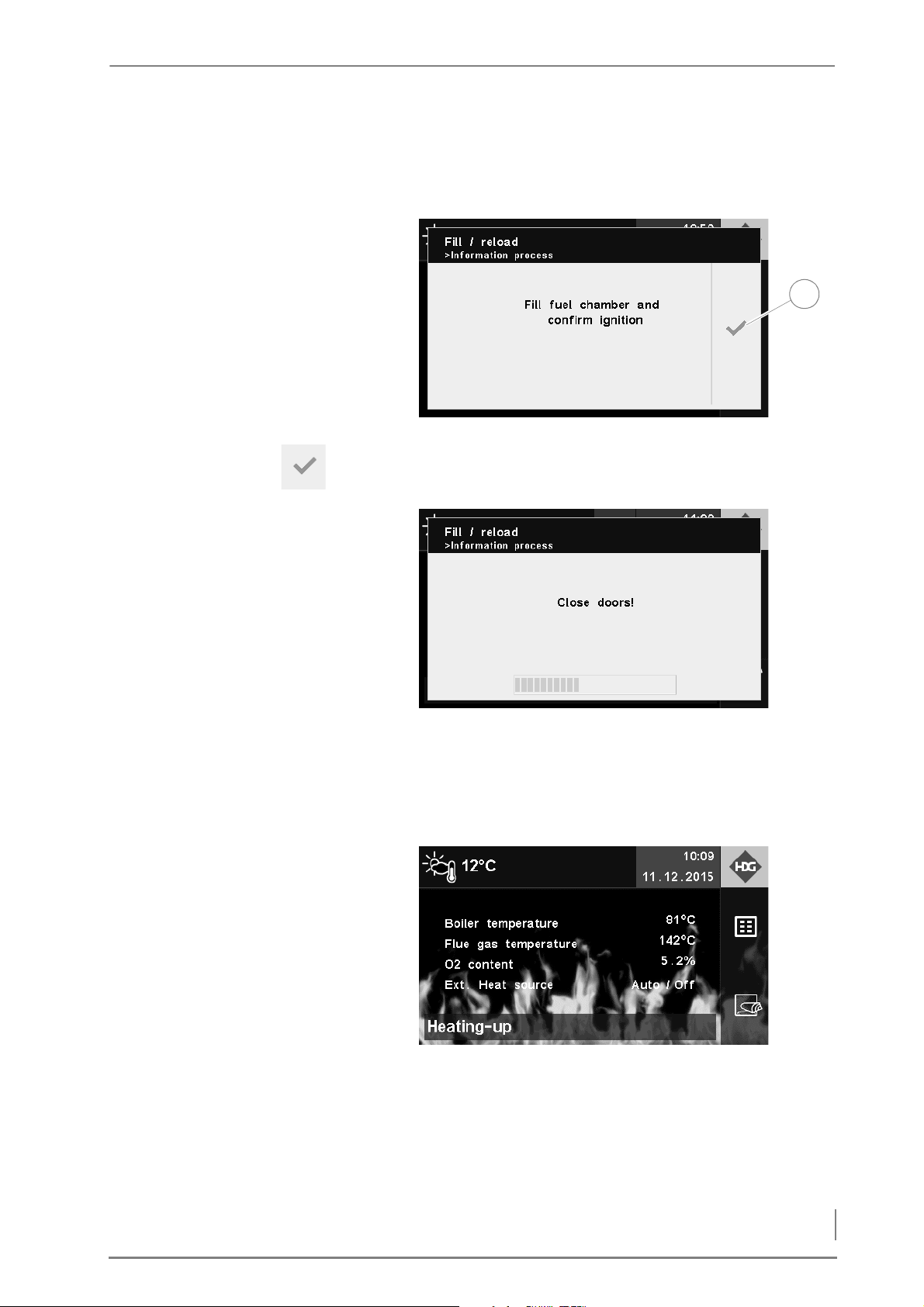
6 Using the heating system – Heating up the system
27.Fill up the fuel chamber (3) with fuel.
1
28.Close the fuel chamber door (1).
29.The message Fill fuel chamber and confirm ignition is displayed.
Figure 6/12 - Filling the fuel chamber and confirming ignition
30.Confirm your input by pressing the Confirm button (1).
✓ The Close doors message appears in the display.
Figure 6/13 - Closing the doors
31.Make sure that all of the doors are closed.
32.Wait until the progress bar is completely full.
33.The Ignite message appears in the display.
Figure 6/14 - Ignition
✓ The HDG F20-50 boiler is now heated up.
LECTRIC IGNITION 24.Stack some highly flammable material (small pieces of dry wood)
E
in front of the igniter gun (2) and about 10 cm high on the burner
nozzle (4) so that it is covered.
57
Page 58
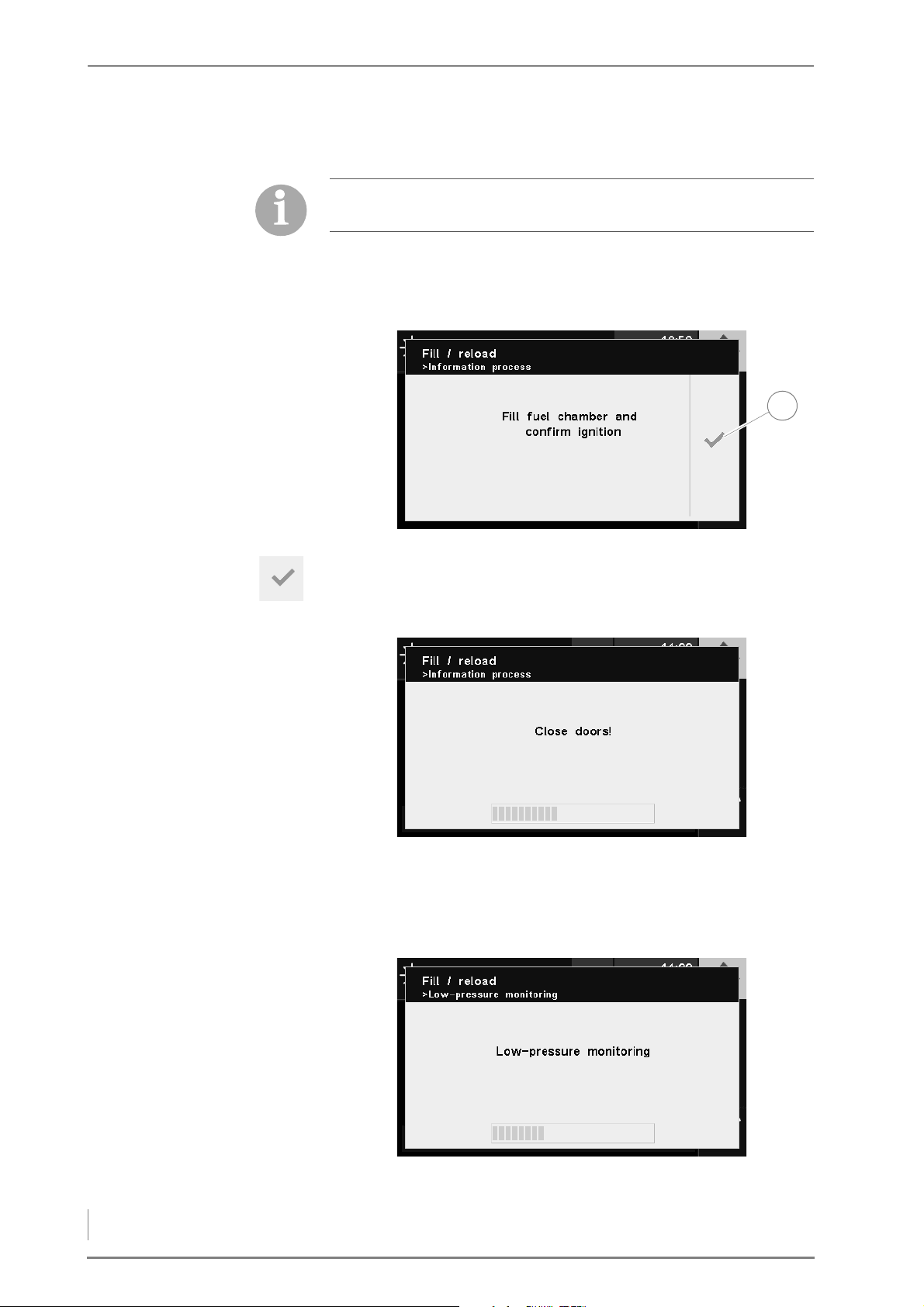
6 Using the heating system – Heating up the system
25.Lay some small pieces of cardboard in front of the igniter gun (2)
1
on the wood inside the fuel chamber (3).
Only put in as much wood as the heating system and accumulator
can absorb as energy.
26.Fill up the fuel chamber (3) with fuel.
27.Close the fuel chamber door (1).
28.The message Fill fuel chamber and confirm ignition is displayed.
Figure 6/15 - Filling the fuel chamber and confirming ignition
29.Confirm your input by pressing the Confirm button (1).
✓ The Close doors message appears in the display.
Figure 6/16 - Closing the doors
30.Make sure that all of the doors are closed.
31.Wait until the progress bar is full.
✓ The Underpressure test message appears in the display.
58
Figure 6/17 - Underpressure test
32.Wait until the progress bar is full.
Page 59
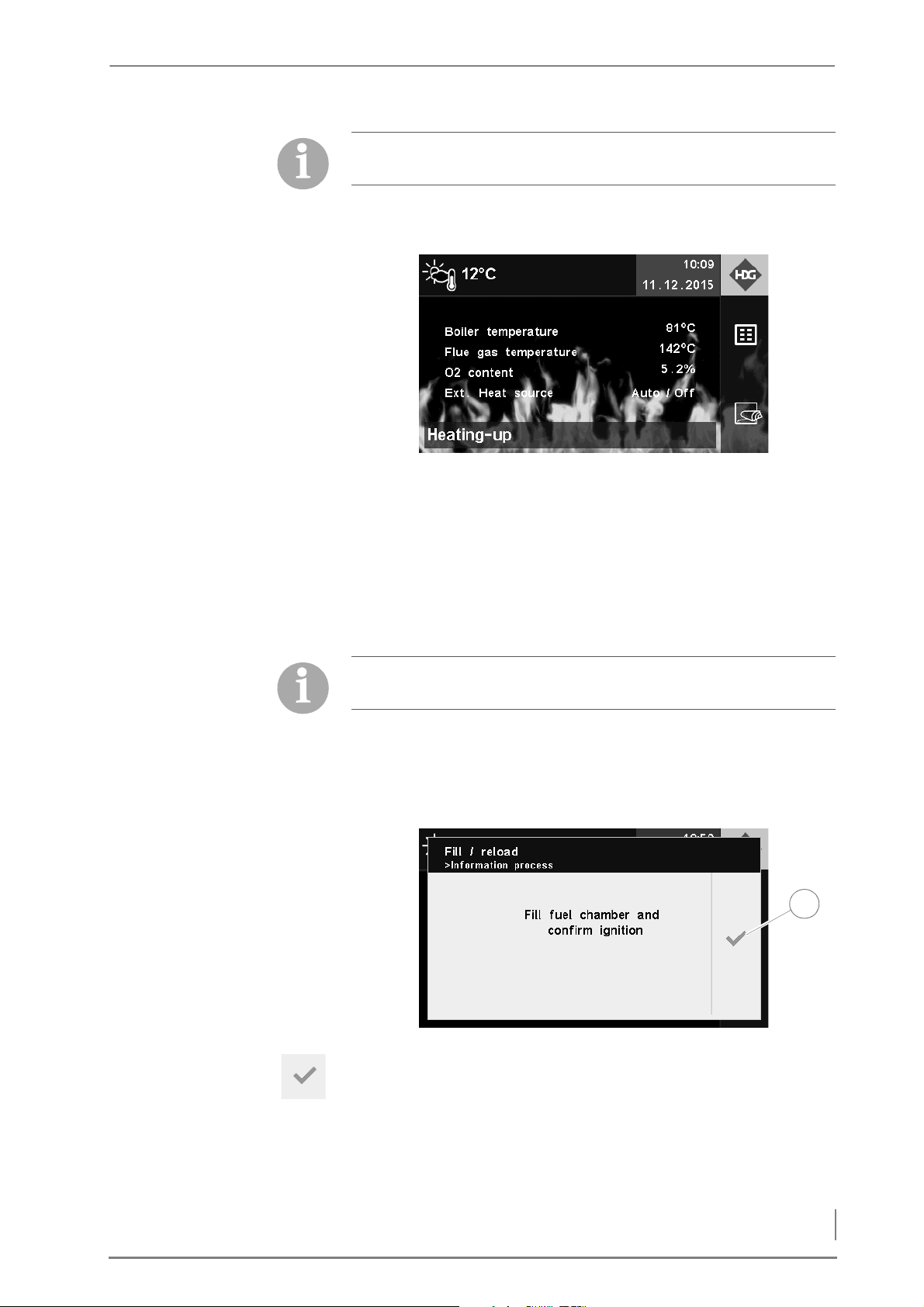
6 Using the heating system – Heating up the system
The differential pressure switch enables the ignition fan if the preset
1
underpressure is reached.
✓ The ignition fan starts.
✓ The Ignite message appears in the display.
Figure 6/18 - Ignition
✓ The HDG F20-50 boiler is now heated up.
UTOMATIC IGNITION 24.Stack some highly flammable material (small pieces of dry wood)
A
in front of the igniter gun (2) and about 10 cm high on the burner
nozzle (4) so that it is covered.
25.Lay some small pieces of cardboard in front of the igniter gun (2)
on the wood inside the fuel chamber (3).
Only put in as much wood as the heating system and accumulator
can absorb as energy.
26.Fill the fuel chamber (3) according to the percentage specified on
the display.
27.Close the fuel chamber door (1).
28.The message Fill fuel chamber and confirm ignition is displayed.
Figure 6/19 - Filling the fuel chamber and confirming ignition
29.Confirm your input by pressing the Confirm button (1).
✓ The Close doors message appears in the display.
59
Page 60
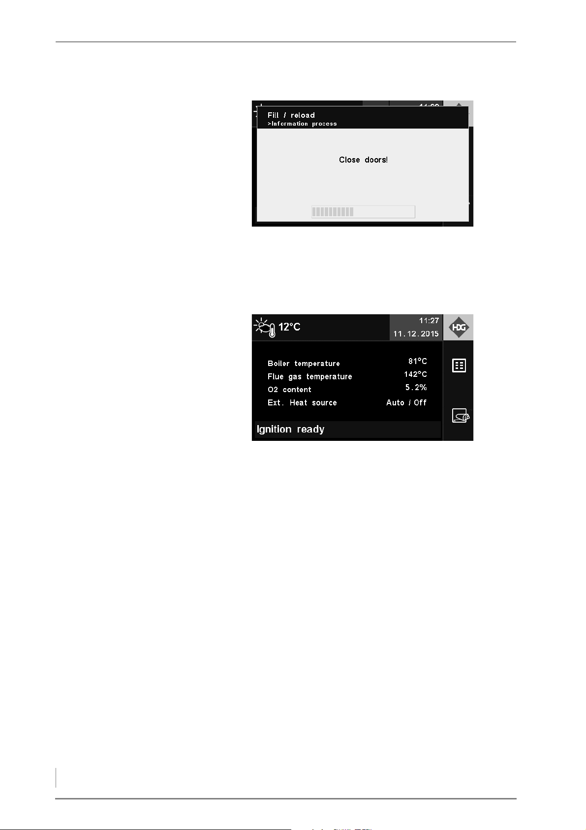
6 Using the heating system – Performing a chimney sweep measurement
Figure 6/20 - Closing the doors
30.Make sure that all of the doors are closed.
31.Wait until the progress bar is full.
✓ The Ready for ignition message appears in the display.
Figure 6/21 - Ready for ignition
✓ The HDG F20-50 boiler is ready for automatic ignition.
6.4 Performing a chimney sweep measurement
In Germany, there is a legal requirement that heating systems with
nominal thermal power in excess of 4 kW be inspected annually by a
qualified combustion engineer to see that federal emission limits for
small and medium-sized boiler systems are met (1st Federal Emission
Control Ordinance).
I
NITIAL TEST The operating company must notify the responsible combustion
engineer of the installation of the heating system before it is
commissioned, and must also arrange an appointment for the
chimney sweep test within four weeks of commissioning. To ensure
a stable operating ability, sufficient heat transfer must occur while
operating at full load.
T
EST EVERY TWO YEARS In Germany, regular inspections every two years must be carried out
in accordance with the requirements of the federal emission limits
(1.BImSchV).
60
Page 61
6 Using the heating system – Performing a chimney sweep measurement
Caution!
Material damage and injury due to incorrect chimney sweep test
The chimney sweep test requires comprehensive technical
knowledge.
Only allow authorised specialists to perform the chimney sweep
test.
BEFORE THE TEST
1. Clean the heating system completely about three to four days
before the chimney sweep test.
✎ See chapter “7 Cleaning and servicing the heating system”,
section “7.1 Cleaning and servicing schedule”.
2. Clean the lambda sensor and check that it is securely mounted,
tighten if necessary.
✎ See chapter “7 Cleaning and servicing the heating system”,
section “7.1 Cleaning and servicing schedule”.
ON THE DAY OF THE TEST
Important!
• The boiler must have been heated at least once during the
period between the cleaning and the chimney sweep test.
• Oak wood, wood briquettes, boards, scrap wood and wood chips
are not suitable for the chimney sweep test.
• At the start of the test the boiler temperature should not be
below 60 °C. The temperature of the accumulator should not be
higher than 60°C. Ensure that the heating circuit has sufficient
heat transfer capacity.
• The heating system must be fitted with a chimney draught
regulator to ensure that the maximum permissible flue draught
requirement of 20 Pa is not exceeded.
• At the start of test, the residual oxygen value should be below
6%.
• Having the test repeated by the combustion engineer or by HDG
specialists will incur charges.
1. On the day of test, heat up the boiler one hour before the
scheduled appointment.
✎ See chapter 6 “Using the heating system”, section 6.3 “Heating up
the heating system”.
2. Only fill the fuel chamber up half way.
61
Page 62
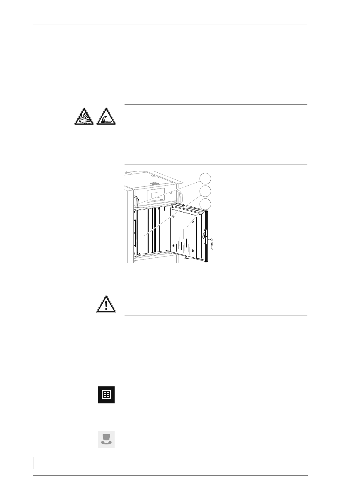
6 Using the heating system – Performing a chimney sweep measurement
3. Use log wood according to fuel recommendation (split, dry wood)
3
1
2
with a length of 50 cm, a maximum diameter of maximum 10 cm
and a maximum water content of 20%.
DURING THE TEST
Danger!
Danger of asphyxiation and explosion from carbon monoxide
When the boiler is in operation, carbon monoxide can be emitted
through the open doors or lids and lead to an explosion.
Always keep the doors and lids closed. Do not leave them open any
longer than necessary and never leave them open unattended.
1. Open the fuel chamber door
(3) slowly.
2. Pull the actuating handle (1)
of the flue gas flap to the front
until it latches into place.
Figure 6/22 - Pull the flue gas flap
3. Carefully tamp the embers and remaining logs together in the fuel
chamber (2) in the presence of the chimney sweep.
Important!
The bed of embers must come up to over the burner nozzle!
4. Fill the fuel chamber (2) half way up evenly and densely with logs
according to the fuel recommendation.
5. Close the fuel chamber door (3).
✓ The actuating handle (1) is released from its lock and the flue gas
flap closes.
6. Wait about 10 - 15 minutes and then start the HDG controls
chimney sweep test.
7. Press the Main menu button in the standard display.
✓ The display switches to the main menu.
8. Press the Messages / Maintenance field.
✓ The display switches to the Messages / Maintenance area.
9. Press the Chimney sweep test field.
✓ A security query appears.
62
Page 63
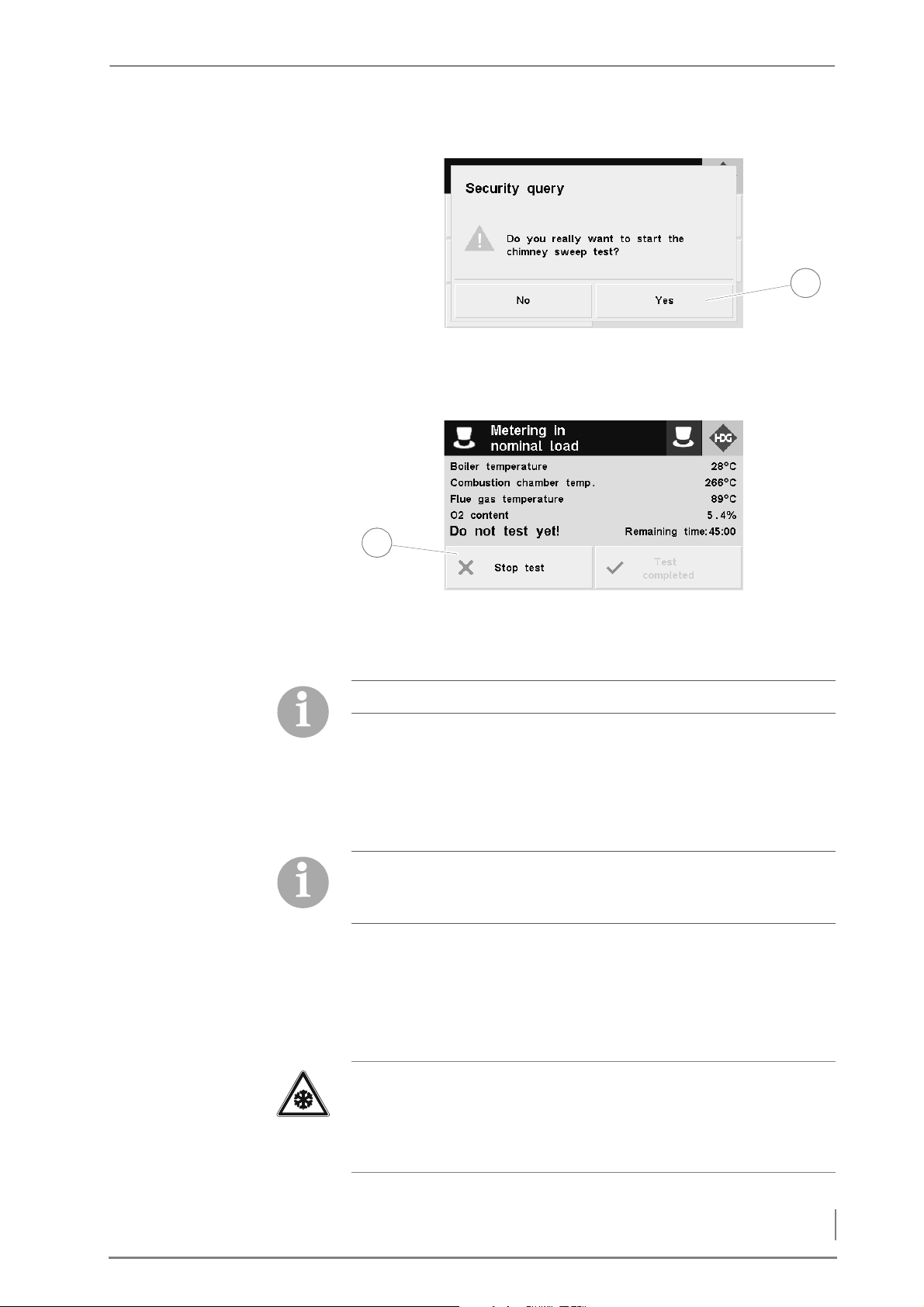
6 Using the heating system – Switching off the heating system for repair work
Figure 6/23 - Chimney sweep test security query
1
1
10.Press Yes (1).
✓ The display switches to the chimney sweep test.
Figure 6/24 - Chimney sweep test
✓ All heating components are activated for heating components.
✓ Do not test yet! is shown on the display
Pressing the Cancel test button (1) cancels the chimney sweep test.
11.Hold off with the test until the thresholds set for the boiler
temperature and for the combustion chamber temperature have
been exceeded.
✓ The display will then show Measurement done.
✓ The chimney sweep test can be started.
If you do not change the operating mode within 45 minutes, the
heating system will automatically return to the previous operating
mode.
6.5 Switching off the heating system for repair work
1. Allow the fire in the boiler to burn out and cool off.
Important!
Frost danger
Only completely shut off the power to the heating system if the
danger of frost can be ruled out.
2. Switch the heating system off.
63
Page 64

6 Using the heating system – Troubleshooting
✎ See the “HDG Control” operating manual, chapter “5 Using the
control unit”, section “5.3 Switching off the heating system”.
There is still electrical voltage in the system.
3. Switch off the emergency heating switch (if installed) or the
corresponding mains electricity circuit breaker.
✓ The heating system is switched off and without current.
6.6 Troubleshooting
If a fault occurs in the heating system, this is shown in the display of
the HDG controls.
✎ See the “HDG Control” operating manual, chapter 10
“Troubleshooting”.
64
Page 65
7 Cleaning and servicing the heating system – Cleaning and servicing schedule
7 Cleaning and servicing the heating system
GENERAL INFORMATION To ensure fault-free and safe operation, certain cleaning and
maintenance work is necessary. This effort will also help you avoid
expensive repairs, provided you observe the recommended
intervals.
The cleaning and maintenance work can also be performed by an
authorised specialist heating company where a servicing contract
has been concluded.
S
PARE PARTS
Only use genuine HDG spare parts. You can obtain HDG spare parts
from your specialist heating company.
7.1 Cleaning and servicing schedule
The specified cleaning intervals are guidelines.
These intervals may vary according to the quality of the fuel and the
power used by the heating system.
Interval Component See page ...
Weekly / as required • Clean the fuel chamber and secondary air
Every 6 months (approx. 900
operating hours)
Annually (approx. 1800
operating hours)
openings
• Clean the secondary combustion chamber and
ash compartment
• Check and clean the lambda sensor
• Clean the flue gas temperature sensor
• Clean the flue gas pipe
• Clean the cleaning system, heat exchanger
surfaces and flue gas flap
• Clean the flue gas fan
• Clean air control unit
• Clean the panels
• Inspect the door seals for leaks
• Clean the ignition fan
Table 7/1 - Cleaning and servicing schedule
67
69
70
71
72
72
76
77
77
78
80
65
Page 66
7 Cleaning and servicing the heating system – Procedure
7.2 Procedure
GENERALLY APPLICABLE SAFETY INSTRUCTIONS
Warning!
Danger of asphyxiation due to carbon monoxide
When the boiler is in operation, carbon monoxide can be emitted
through the open doors, lids or other cleaning openings.
When performing cleaning and maintenance work, do not leave the
cleaning openings, doors and lids open any longer than necessary.
Caution!
Danger of burns from hot surfaces
During operation, the boiler surfaces under the cladding are hot.
Even when turned off, they only cool down slowly.
Switch the heating system off and only start with the cleaning and
maintenance work when the surfaces have cooled down.
Warning!
Danger of fire
When the heating system is in operation, open doors and lids
constitute a fire hazard.
Always keep the doors and lids closed. Only open them when the
boiler has finished burning. Do not leave them open any longer
than necessary and never leave them open unattended.
Warning!
Danger of fire from combustion residues
The combustion residue (ash, coal, etc.) can catch fire again after
being removed from the boiler.
Let the combustion residue cool off before you vacuum and put the
ashes in an appropriate, non-flammable container.
Important!
Before the start of the cleaning and maintenance tasks, the display
of the HDG Control Touch control unit must show the Ready
message.
66
Page 67
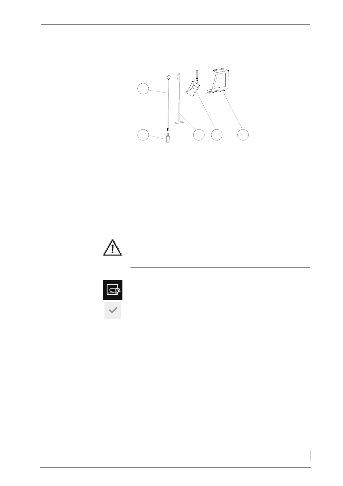
7 Cleaning and servicing the heating system – Procedure
CLEANING TOOLS
2 3
1
4 5
Figure 7/1 - Cleaning tools
1 Brush handle
2Cleaning brush
3Scraper
4 Ash shovel
5 Wall holder
CLEANING THE FUEL CHAMBER AND SECONDARY AIR OPENINGS
Important!
✎ Observe the “Generally applicable safety instructions” in this
section.
1. Allow the fire in the boiler to burn out and cool off.
1. Press the Reload button on the HDG Control Touch control unit.
2. The Fill up / Reload window appears in the display.
3. Confirm your entry by pressing the Confirm button.
✓ The Do not open fuel chamber door message appears in the display.
✓ The flue gas fan is running.
4. Wait until the progress bar is full.
✓ The Open fuel chamber door to safety position message appears in
the display.
5. Open the fuel chamber door to the safety position.
6. Wait until the progress bar is full.
✓ The Open fuel chamber door slowly message appears in the display.
67
Page 68
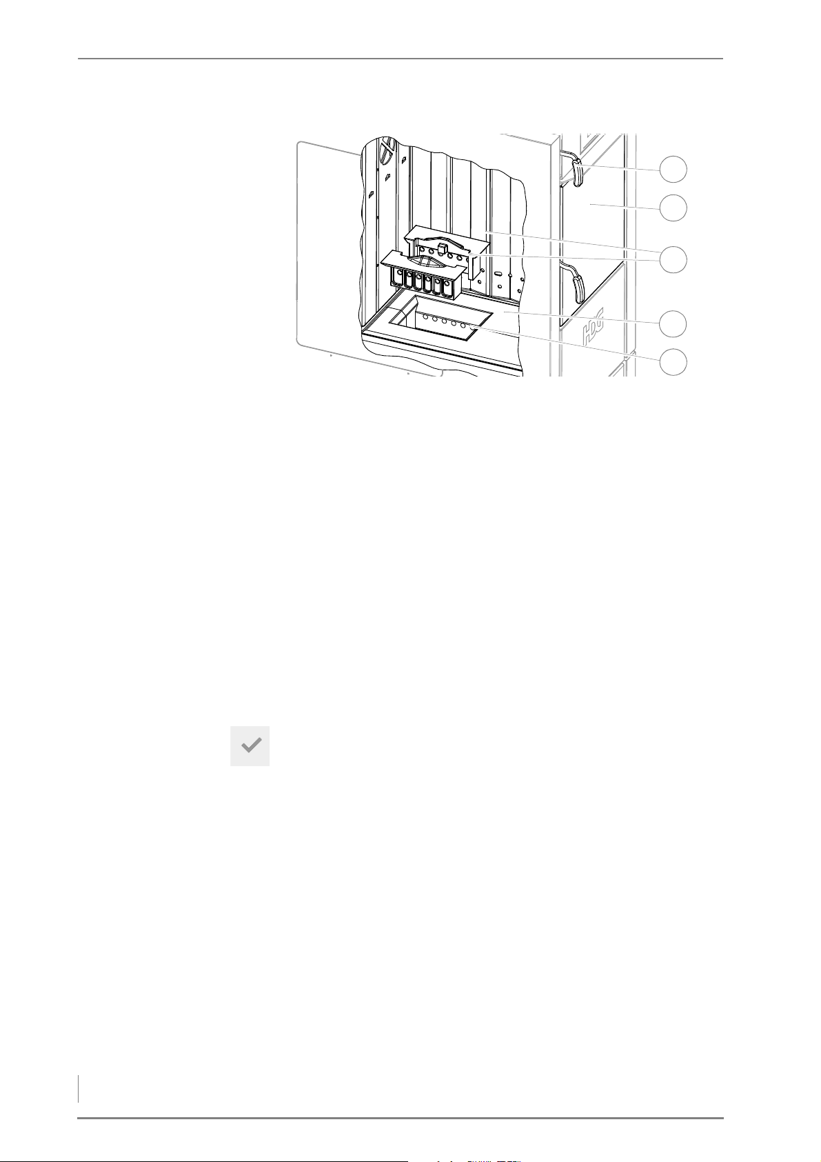
7 Cleaning and servicing the heating system – Procedure
Figure 7/2 - Cleaning the fuel chamber and secondary air openings
5
3
1
2
4
7. Open the fuel chamber door (2).
8. Pull the actuating lever (1) of the flue gas flap to the front until it
latches into place.
9. Check the fuel chamber (4) for ash and any other dirt and, if
necessary, remove this from the fuel chamber using the supplied
cleaning tools.
10.Leave any unburnt pieces of wood and charcoal in the fuel
chamber (4).
11.Remove the two-piece burner nozzle (3).
12.Clean the secondary air openings (5) with the cleaning tool
supplied or with a vacuum cleaner.
13.Carefully reinsert the burner nozzle (3).
14.Close the fuel chamber door (2).
✓ The actuating lever (1) of the flue gas flap is unlocked.
15.Press the Confirm button on the display.
✓ On the display of the control unit, the Ready message appears.
✓ The fuel chamber and the secondary air openings have been
68
cleaned.
Page 69
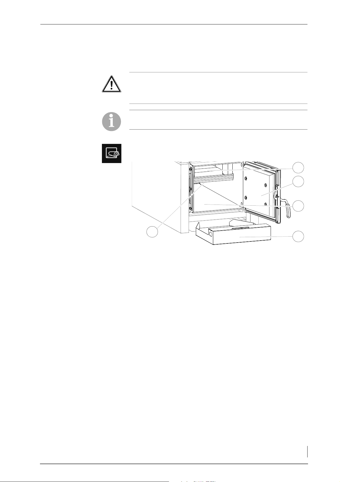
7 Cleaning and servicing the heating system – Procedure
CLEANING THE SECONDARY COMBUSTION CHAMBER AND THE ASH
2
4
1
5
3
COMPARTMENT
Important!
✎ Observe the “Generally applicable safety instructions” in this
section.
During the heating period, the secondary combustion chamber and
the ash compartment must be cleaned two to three times a week.
1. Allow the fire in the boiler to burn out and cool off.
2. Press the Reload button.
Figure 7/3 - Cleaning the secondary combustion chamber and the ash compartment
3. Pull out the ash pan (4) approx. 30 cm.
4. Open the combustion chamber door (2).
5. Check the secondary combustion chamber (1) and the ash
compartment (3) for ash and any other dirt.
6. Remove any deposits on the bottom of the combustion chamber
lining (5) with the supplied cleaning tool.
7. Using the supplied cleaning tools and without moving the
combustion chamber stones, carefully pull out the combustion
residue from the secondary combustion chamber (1) in the ash
compartment (3).
8. Using the supplied cleaning tools, pull the combustion residue
out of the ash compartment (3) into the ash pan (4).
9. Empty the combustion residue into a fireproof container.
10.Close the boiler in the reverse order.
✓ The secondary combustion chamber and the ash compartment
have been cleaned.
69
Page 70
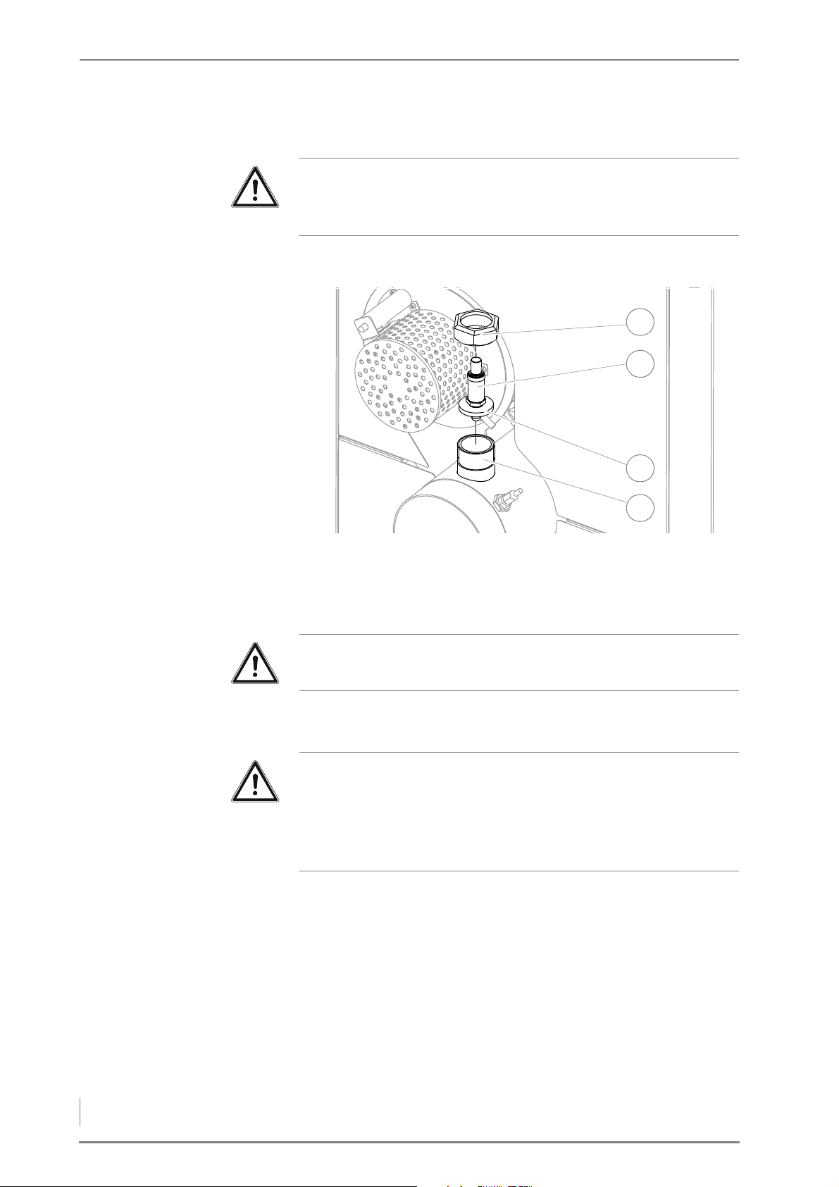
7 Cleaning and servicing the heating system – Procedure
CHECKING AND CLEANING THE LAMBDA SENSOR
1
3
2
4
Important!
✎ Observe the “Generally applicable safety instructions” in this
section.
1. Allow the fire in the boiler to burn out and cool off.
Figure 7/4 - Cleaning the lambda sensor
2. Unscrew the union nut (1) with a pipe wrench.
3. Remove the lambda sensor (2) and the steel washer (3) under it
from the connection nozzle (4) of the flue gas pipe.
Important!
Steel bristles will damage the lambda sensor.
4. Clean the lambda sensor (2) with a vacuum cleaner.
5. Clean out any deposits inside the connection nozzle (4).
Important!
When reinstalling the lambda sensor, make sure its seal is intact.
Use a pipe wrench to tighten the union nut. Do not tighten the
lambda sensor excessively. Never tighten the lambda sensor by the
shaft body.
6. Reinstall the lambda sensor (2) in the reverse sequence.
7. Check the lambda sensor (2) for a secure fit.
8. Carefully tighten the lambda sensor (2) with a 22 mm spanner.
✓ The lambda sensor has been checked and cleaned.
70
Page 71
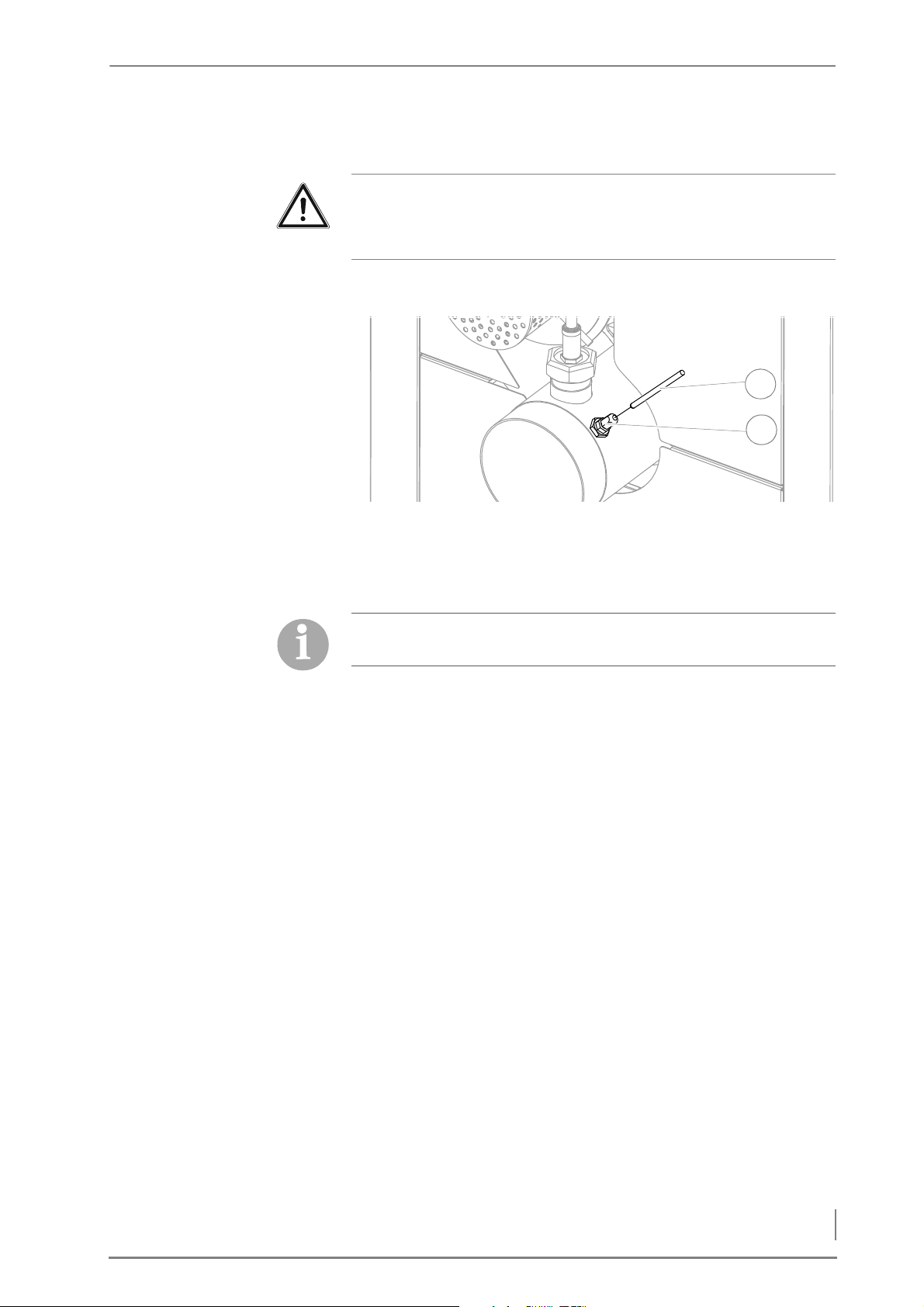
7 Cleaning and servicing the heating system – Procedure
CLEANING THE FLUE GAS TEMPERATURE SENSOR
2
1
Important!
✎ Observe the “Generally applicable safety instructions” in this
section.
1. Allow the fire in the boiler to burn out and cool off.
Figure 7/5 - Cleaning the flue gas temperature sensor
2. Loosen the M10 union nut (SW 17) (2) and pull the flue gas
temperature sensor (1) out of the clamp screw connections.
3. Clean the sensor surface with a moist cloth.
The flue gas temperature sensor must be installed so that the
sensor element projects approx. 2 cm out of the clamp screw.
4. Mount the flue gas temperature sensor (1) in the reverse
sequence.
✓ The flue gas temperature sensor has been cleaned.
71
Page 72
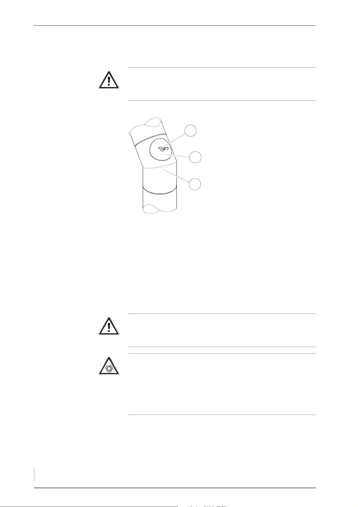
7 Cleaning and servicing the heating system – Procedure
CLEANING THE FLUE GAS PIPE
1
2
3
Important!
✎ Observe the “Generally applicable safety instructions” in this
section.
1. Allow the fire in the boiler to burn out and cool off.
2. Unscrew the wing nut (1) on
the inspection hatch cover (2).
3. Remove the inspection hatch
cover (2) from the flue gas
pipe (3).
4. Check whether the flue gas
pipe (3) needs cleaning.
5. If necessary, extract the ash
from the flue gas pipe (3)
using a vacuum cleaner.
Figure 7/6 - Clean the flue gas pipe
6. Sweep any deposits into the flue gas collection box, but not in the
direction of the boiler.
7. Screw the inspection hatch (2) securely back onto the flue gas
pipe (3) with the wing nut (1).
✓ The cleaning of the flue gas pipe is completed.
CLEANING THE CLEANING SYSTEM, HEAT EXCHANGER SURFACES AND
FLUE GAS FLAP
Important!
✎ Observe the “Generally applicable safety instructions” in this
section.
Caution!
Risk of injury from automatically driven components
Working on the flue gas fan can lead to hand injuries due to the
moving parts.
Disconnect the boiler from the power mains when working on the
flue gas fan.
72
Page 73
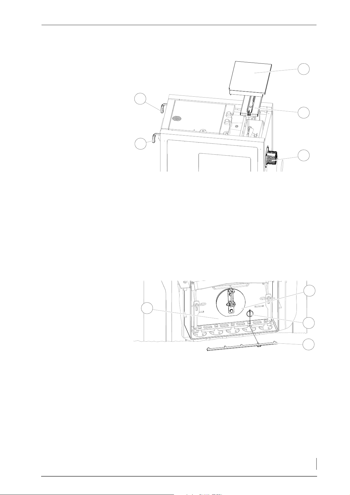
7 Cleaning and servicing the heating system – Procedure
1. Allow the fire in the boiler to burn out and cool off.
2
5
4
1
3
4
3
1
2
Figure 7/7 - Dismantling the cleaning shaft lid
2. Disconnect the plug from the flue gas fan (3).
3. Remove the cover of the cleaning shaft lid (5).
4. Unscrew the two M8 wing nuts and lift the cleaning shaft lid (4) up
and out.
HDG F20/25/30
5. Open the fuel chamber door.
6. Pull the actuating handle (2) of the cleaning system several times
and check whether the cleaning mechanism moves freely.
7. Pull the actuating handle (1) of the flue gas flap to the front until it
latches into place.
Figure 7/8 - Cleaning the flue gas flap
8. Inspect the cleaning shaft (1) for deposits.
9. If necessary, remove deposits and dust with a vacuum cleaner.
10.Clean the flue gas flap (4) and the suction channel behind it with
a suitable cleaning tool (e.g. scraper) or with a vacuum cleaner.
11.Unlatch the actuating handle of the flue gas flap.
12.Remove the lynch pin (3).
73
Page 74
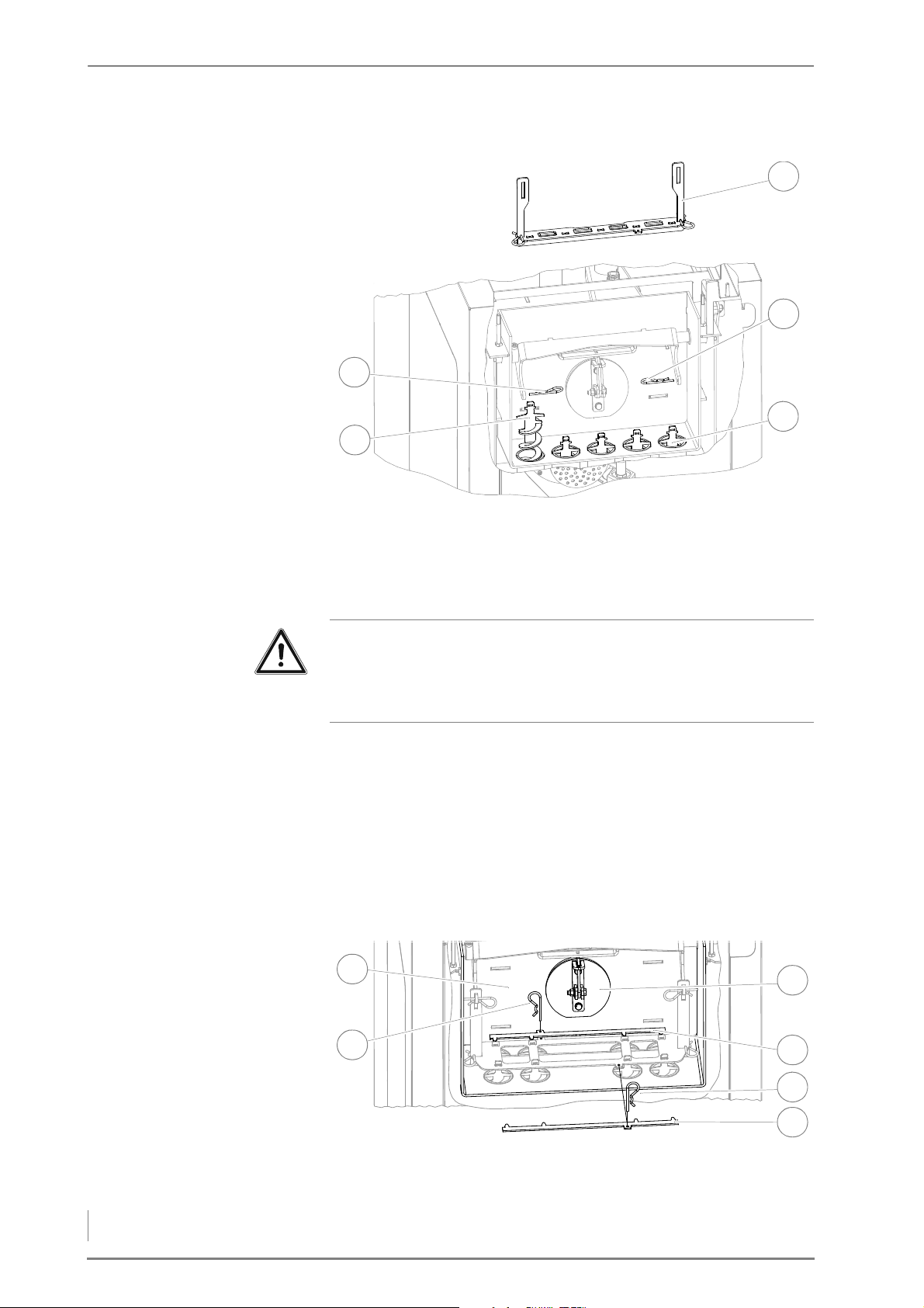
7 Cleaning and servicing the heating system – Procedure
13.Remove the retaining plate (2) for the turbulators.
5
4
2
1
3
6
5
1
3
2
4
Figure 7/9 - Pulling out the cleaning turbulators
14.Pull out the two clip connectors (1 + 4).
15.Lift out the large guide crossbar (5) in an upward direction.
HDG F40/50
16.Pull out the cleaning turbulators (2) in an upward direction.
Important!
When cleaning the heat exchanger surfaces, always first push the
cleaning brush all the way down and through before you pull it up
again, so that the wire bristles of the brush are not bent.
17.Clean the heat exchanger pipes (3) using the round cleaning
brush.
18.Mount the cleaning turbulators in the reverse sequence.
19.Close the boiler in the reverse sequence.
20.Make sure that the cleaning shaft lid is closed properly.
✓ The cleaning system, the heat exchanger surfaces and the flue gas
flap have been cleaned.
Figure 7/10 - Cleaning the flue gas flap
74
8. Inspect the cleaning shaft (1) for deposits.
Page 75
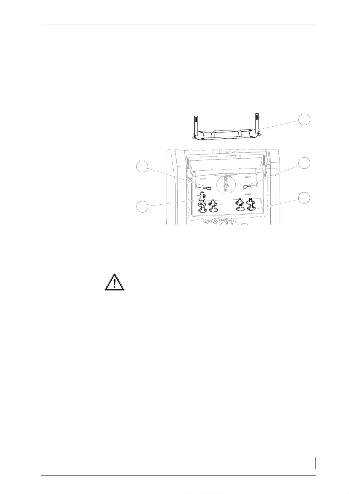
7 Cleaning and servicing the heating system – Procedure
9. If necessary, remove deposits and dust with a vacuum cleaner.
5
4
2
1
3
10.Clean the flue gas flap (6) and the suction channel behind it with
a suitable cleaning tool (e.g. scraper) or with a vacuum cleaner.
11.Unlatch the actuating handle of the flue gas flap.
12.Remove the clip connectors (2 + 4).
13.Remove the retaining plate (3 + 5) for the turbulators.
Figure 7/11 - Pulling out the cleaning turbulators
14.Pull out the two clip connectors (1 + 4).
15.Lift out the large guide crossbar (5) in an upward direction.
16.Pull out the cleaning turbulators (2) in an upward direction.
Important!
When cleaning the heat exchanger surfaces, always first push the
cleaning brush all the way down and through before you pull it up
again, so that the wire bristles of the brush are not bent.
17.Clean the heat exchanger pipes (3) using the round cleaning
brush.
18.Mount the cleaning turbulators in the reverse sequence.
19.Close the boiler in the reverse sequence.
20.Make sure that the cleaning shaft lid is closed properly.
✓ The cleaning system, the heat exchanger surfaces and the flue gas
flap have been cleaned.
75
Page 76
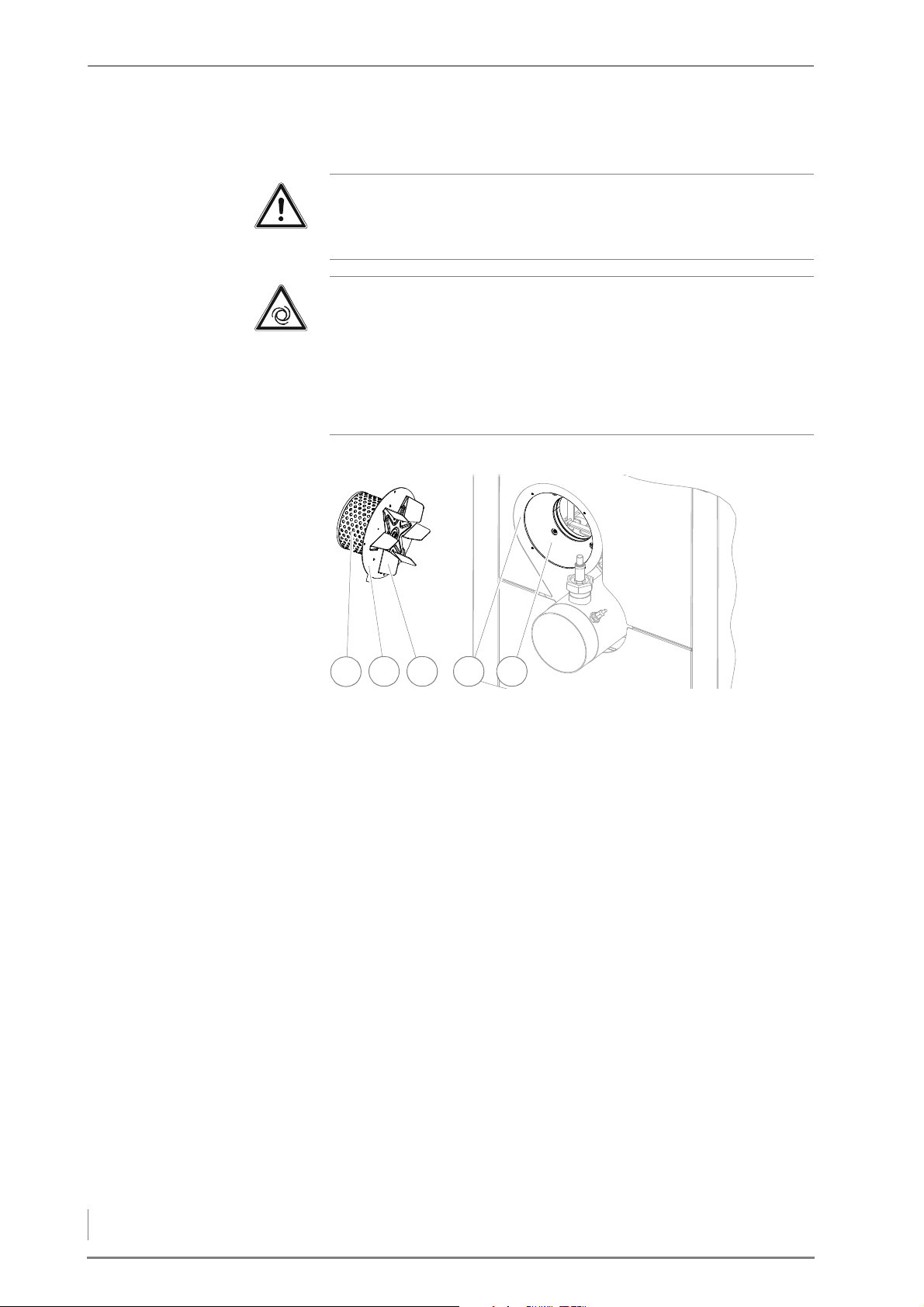
7 Cleaning and servicing the heating system – Procedure
CLEANING THE FLUE GAS FAN
213 4 5
Important!
✎ Observe the “Generally applicable safety instructions” in this
section.
Caution!
Risk of injury from automatically driven components
Working on the flue gas fan can lead to hand injuries due to the
moving parts.
Disconnect the boiler from the power mains when working on the
flue gas fan.
1. Allow the fire in the boiler to burn out and cool off.
Figure 7/12 - Removing the flue gas fan
2. Disconnect the plug from the flue gas fan (1).
3. Undo the four M4 hexagon socket screws (SW3) and remove the
flue gas fan (1) from the boiler.
4. Clean the flue gas collection box (5) with a vacuum cleaner.
5. Clean the fan wheel (3) and the annular gap behind it with a
cleaning tool.
6. Inspect the contact surfaces (2 + 4) of the flue fan and the flue gas
collection box.
7. Reinstall the flue gas fan in the reverse sequence.
✓ The flue gas fan has been cleaned.
76
Page 77
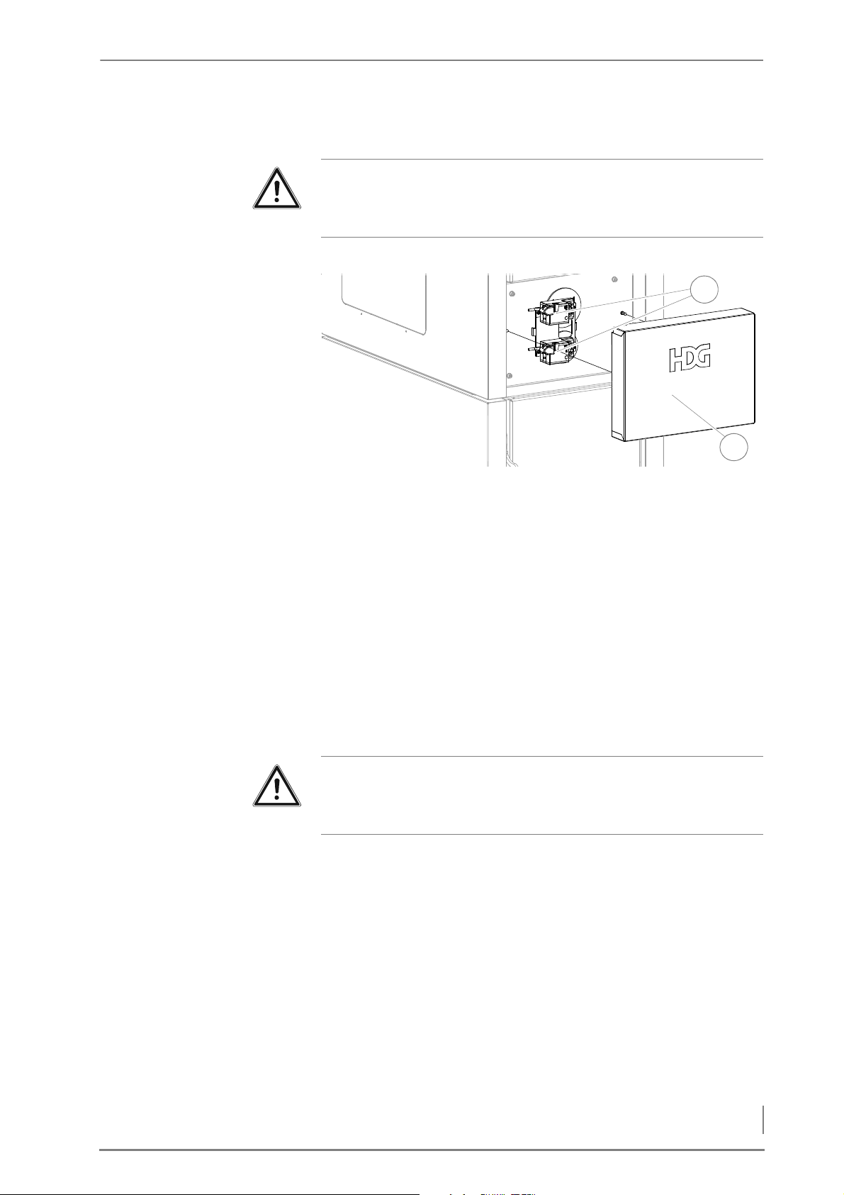
7 Cleaning and servicing the heating system – Procedure
CLEANING THE AIR CONTROL UNIT
1
2
Important!
✎ Observe the “Generally applicable safety instructions” in this
section.
1. Allow the fire in the boiler to burn out and cool off.
Figure 7/13 - Cleaning the air control unit
2. Pull the cladding (2) of the air regulation unit (1) carefully
forwards.
3. Use a fine brush and a vacuum cleaner to remove dust deposits
from the fan control unit (1).
4. Carefully press on the two rotary vanes behind the actuators and
make sure that these can move.
5. Close the air control unit in reverse order.
✓ The air control unit is cleaned.
CLEANING THE PANELS
Important!
✎ Observe the “Generally applicable safety instructions” in this
section.
77
Page 78
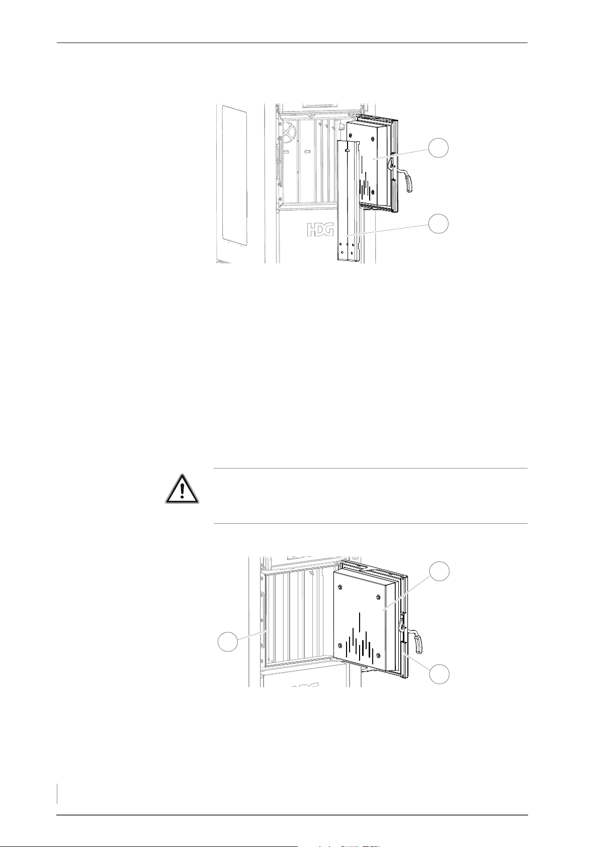
7 Cleaning and servicing the heating system – Procedure
1. Allow the fire in the boiler to burn out and cool off.
1
2
3
1
2
Figure 7/14 - Clean the panels
2. Open the fuel chamber door (1).
3. Unhook the side, rear and front panels (2).
4. Clean the panels (2) with the scraper.
5. Clean the fuel chamber walls with the scraper.
6. Reinstall the panels (2) in reverse order.
7. Close the fuel chamber door (1).
✓ Cleaning of the panels is complete.
CHECKING THE DOORS ARE TIGHT
Important!
✎ Observe the “Generally applicable safety instructions” in this
section.
FUEL CHAMBER DOOR 1. Allow the fire in the boiler to burn out and cool off.
Figure 7/15 - Checking the fuel chamber door for leaks
2. Open the fuel chamber door (1).
✎ See “Cleaning the fuel chamber and secondary air openings” in
78
this section.
Page 79
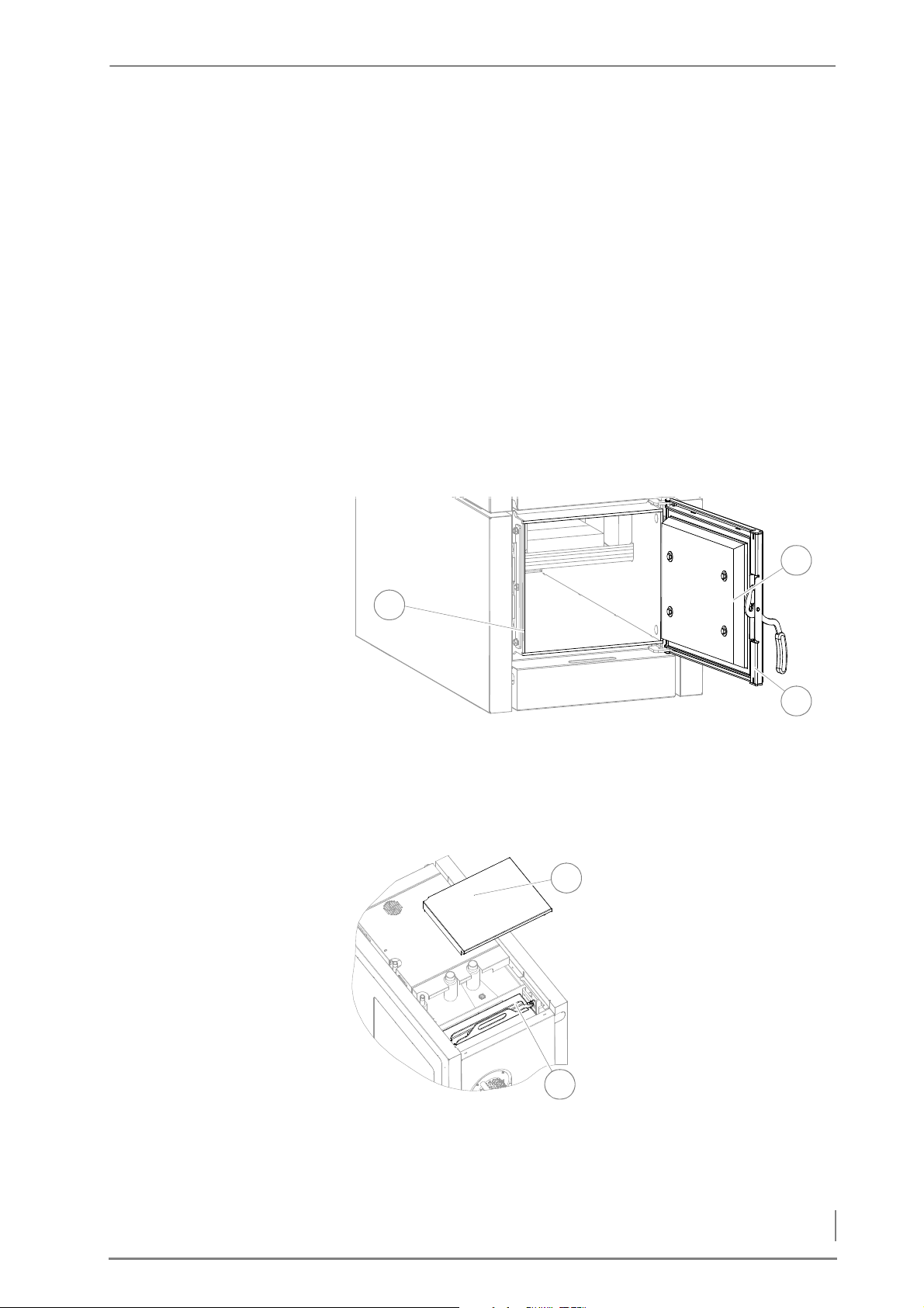
7 Cleaning and servicing the heating system – Procedure
C
3
1
2
1
2
OMBUSTION CHAMBER DOOR
3. Clamp a sheet of paper (approx. 30 cm long and 2 cm wide)
between the contact surface (3) and the seal (2) of the fuel
chamber door.
4. Close the fuel chamber door (1).
5. Pull on the paper.
✓ If the paper moves, the door is not properly sealed.
✓ If the paper does not move, the door is properly sealed.
6. If necessary, position the locking plate so that the door closes
firmly again.
7. Repeat the procedure from step 2 to step 6 until you have
inspected all four of the contact surfaces (3).
8. Remove the paper and close the fuel chamber door (1).
✓ The inspection of the fuel chamber door is complete.
LEANING SHAFT LID
C
Figure 7/16 - Checking the combustion chamber door for leaks
9. Check the sealing of the ash door (1) exactly as described above
under “Fuel chamber door”.
✓ The combustion chamber door has been checked for tightness.
10.Lift off the cover (1) of the
cleaning shaft lid (2).
11.Make sure that the cleaning
shaft lid (2) does not leak.
12.If necessary, tighten the two
M8 wing nuts.
✓ The inspection of the cleaning
shaft lid seal is complete.
Figure 7/17 - Checking the cleaning shaft lid for leaks
79
Page 80
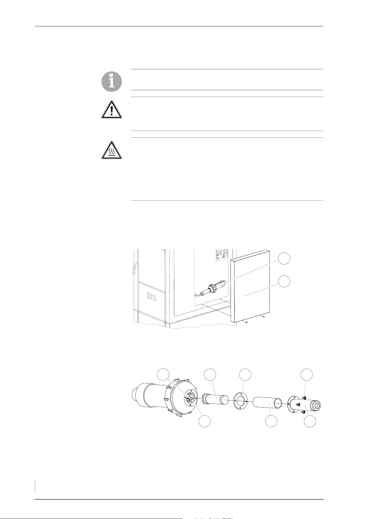
7 Cleaning and servicing the heating system – Procedure
CLEANING THE IGNITION FAN
1
2
1
6 5
432
7
The ignition fan is only available in connection with the HDG
automatic ignition system.
Important!
✎ Observe the “Generally applicable safety instructions” in this
section.
Caution!
Danger of burns from hot surfaces
The hot air nozzle of the ignition fan becomes very hot during
operation. Even when turned off, it only cools down slowly.
Switch the heating system off and only start with the cleaning and
maintenance work once the hot air nozzle has cooled down.
1. Switch the heating system off.
✎ See the “HDG controls” operating manual, chapter “5 Using the
control unit”, section “5.3 Switching off the heating system”.
2. Allow the fire in the heating system to burn out and cool down.
Figure 7/18 - Removing the cover
3. Undo the fastening screws and remove the side cover (2).
4. Pull the ignition fan (1) out of the retainer.
Figure 7/19 - Checking and cleaning the ignition fan
5. Unscrew the four M4 stainless steel slotted screws (4) of the hot air
6. Pull off the hot air nozzle (5).
7. Remove the insulating tube (6) and the seal (3).
80
nozzle (5).
Page 81

7 Cleaning and servicing the heating system – Procedure
8. Pull the heating element (2) out of the plug contacts (7).
9. Check the heating element (2) for dirt.
10.Remove any dirt by blowing it off.
11.Check the photocell (1) for dirt.
12.Remove any dirt using a cotton swab.
13.Reinstall the ignition fan into the heating system in the reverse
sequence.
14.Fit the side cover.
15.Re-starting the heating system.
✓ The cleaning of the ignition fan is completed.
81
Page 82
8 Notes on dismantling and disposal – Dismantling
8 Notes on dismantling and disposal
8.1 Dismantling
Danger!
Material damage and personal injury due to incorrect dismantling
Dismantling the system requires comprehensive specialist
knowledge. If the boiler is dismantled by an untrained person,
injuries may occur.
Only allow authorised specialists to dismantle the system.
The boiler can be dismantled as follows:
1. Allow the fire in the boiler to burn out and cool off.
Danger!
Dangerous electrical current or voltage
The heating system can only be completely de-energised by
switching off the mains circuit breaker or the emergency heating
switch.
2. Switch off the heating system at the emergency heating switch or
the mains circuit breaker.
✎ See chapter “6 Using the heating system”, section “6.5 Switching
off the heating system for repair work”.
✓ The system has been de-energised.
✓ The control is deactivated.
3. Disconnect the boiler from the electrical power supply.
4. Once it has cooled down, drain the heating water from the system.
5. Observe the safety regulations for personnel when disconnecting
the boiler from the heating system.
6. Dismantle the individual components of the boiler.
✓ The boiler has been dismantled.
82
Page 83

8 Notes on dismantling and disposal – Disposal
8.2 Disposal
The following components are made of steel and can be recycled via
a local recycling centre.
• Boiler
• Cladding
The electrical components can also be recycled via a local recycling
centre.
Fibreglass, mineral wool and plastic parts should be brought to the
relevant waste disposal centres.
Oily or greasy components and condensers may only be disposed
of through a specialist waste disposal centre.
83
Page 84

9 Declaration of Conformity
9 Declaration of Conformity
EC Declarationof Conformity
in accordance with Section A of Part 1 of Annex II of the
EC Directive 2006/42 on machinery
Producer:
HDG Bavaria GmbH, Heating system for wood
Siemensstraße 22
D-84323 Massing
Resident of the EC authorized to assemble the adequate technical documentation:
Stefan Holfelder
HDG Bavaria GmbH, Heating system for wood
Siemensstraße 22
D-84323 Massing
Description and identification of the machinery:
Product: HDG F
Type: HDG F10-50
We definitely declare hereby that the machinery complies with each and every relevant provision of
the following EC Directives:
2006/42/EC:2006-05-17 EC Directive on machinery 2006/42/EC
2006/95/EC: (Low Voltage Directive) Directive of the European Parliament and of the Council of 12 December 2006 on
the harmonisation of the laws of Member States relating to Electrical Equipment designed for use within
certain voltage limits (codified version) (1)
2004/108/EC: Directive 2004/108/EC of the European Parliament and of the Council of 15 December 2004 on the
approximation of the laws of the Member States relating to electromagnetic compatibility and repealing
Directive 89/336/EEC
97/23/EC: (Pressure Equipment) Directive 97/23/EC on the approximation of the laws of the Member States
concerning pressure equipment
In accordance with section 2 of article 7 the applied harmonized regulations are to be found under:
EN 60335-1:2002 Household and similar electrical appliances Safety - Part 1: General requirements
EN ISO 12100-1:2003-11 Safety of machinery ― Basic concepts, general principles for design -
Part 1: Basic terminology, methodology
EN ISO 12100-2:2003-11 Safety of machinery ― Basic concepts, general principles for design - Part 2: Technical principles
EN 60204-1:2006-06 Safety of Machinery - Electrical Equipment of Machines - Part 1: General requirements
EN ISO 14121-1:2007 Safety of machinery –Risk assessment - Part 1: Principles (ISO 14121-1:2007)
Further technical standards and specifications applied are to be found under:
EN 303-5:1999 Part 5: Heating boilers for solid fuels, hand and automatically fired, nominal heat output of up to 300 kW.
Terminology, requirements, testing and marking
Massing, 28.08.2014
-----------------------------------------------------------------------------------------------------------------------------
---------------
Place, date
Signature
Martin Ecker
CEO
84
Page 85

10 Index
10 Index
A
Accumulator . . . . . . . . . . . . . . . . . . . . . . . . . . . . . . . 28
Actuator
Air inlet cross section
Ash compartment
Ash pan
. . . . . . . . . . . . . . . . . . . . . . . . . . . . . . . . . . . . 7
- primary air
-secondary air
. . . . . . . . . . . . . . . . . . . . . . . . . . . . 13
. . . . . . . . . . . . . . . . . . . . . . . . . . 13
. . . . . . . . . . . . . . . . . . . 19, 20
. . . . . . . . . . . . . . . . . . . . . . . . . . 14
. . . . . . . . . . . . . . . . . . . . . . . . . . . . . . . . . . . 13
B
Back-up fuse . . . . . . . . . . . . . . . . . . . . . . . . . . . . . . . 18
Boiler class
Boiler control unit
Boiler installation site
Burner nozzle
. . . . . . . . . . . . . . . . . . . . . . . . . . . . . 18, 19
. . . . . . . . . . . . . . . . . . . . . . . . . . 17
. . . . . . . . . . . . . . . . . . . . . . 24
. . . . . . . . . . . . . . . . . . . . . . . . . . . . . . 14
C
Central module . . . . . . . . . . . . . . . . . . . . . . . . . . . . 14
Checking and cleaning
- the ignition fan
Checking the combustion chamber door
- for tightness
Chimney
Chimney sweep test
Cleaning and servicing schedule
Cleaning motor
Cleaning shaft lid
Cleaning system
Cleaning the
Cleaning tools
Cleaning turbulators
CO2 content
Combustion chamber door
Combustion duration
Commissioning the system
. . . . . . . . . . . . . . . . . . . . . . . . . . . . . . . . . . . 26
-Connecting
-cleaning
- lambda sensor
- secondary combustion chamber
. . . . . . . . . . . . . . . . . . . . . . . . . . . . . . 72
. . . . . . . . . . . . . . . . . . . . . . . . . . . 18, 19
. . . . . . . . . . . . . . . . . . . . . . . . 80
. . . . . . . . . . . . . . . . . . . . . . . . . . 79
. . . . . . . . . . . . . . . . . . . . . . . . . . . 45
. . . . . . . . . . . . . . . . . . . . . . . 60
. . . . . . . . . . . . 65
. . . . . . . . . . . . . . . . . . . . . . . . . . . . 15
. . . . . . . . . . . . . . . . . . . . . . . . . . 14
. . . . . . . . . . . . . . . . . . . . . . . . . . . 13
. . . . . . . . . . . . . . . . . . . . . . . . 70
. . . . . . . 69
. . . . . . . . . . . . . . . . . . . . . . . . . . . . . 67
. . . . . . . . . . . . . . . . . . . . . . . 14
. . . . . . . . . . . . . . . . . 13
. . . . . . . . . . . . . . . . . . 19, 20
. . . . . . . . . . . . . . . . . 48
D
Declaration of Conformity . . . . . . . . . . . . . . . . . . 84
Dimensions
DIN EN ISO 17225
Dismantling
Display
Disposal
. . . . . . . . . . . . . . . . . . . . . . . . . . . . . . . . 23
. . . . . . . . . . . . . . . . . . . . . . . . . . 20
. . . . . . . . . . . . . . . . . . . . . . . . . . . . . . . 82
. . . . . . . . . . . . . . . . . . . . . . . . . . . . . . . . . . . . . 7
. . . . . . . . . . . . . . . . . . . . . . . . . . . . . . . . . . . 83
E
Efficiency . . . . . . . . . . . . . . . . . . . . . . . . . . . . . . 18, 19
Electrical power consumption
Electrical system
EM8 extension module
EM8+4 extension module
Emergency heating switch
Extension module EM4
-Mounting
. . . . . . . . . . . . . . . . . . . . . . . 28, 45
. . . . . . . . . . . . . . . . . . . . . 36
. . . . . . . . . . . . . . . . . . . . . . . . . . . . . 36
. . . . . . . . . . 18, 19
. . . . . . . . . . . . . . . . . . 36
. . . . . . . . . . . . . . . . . 50
F
Filling/draining . . . . . . . . . . . . . . . . . . . . . . . . 18, 20
-connection
Flue calculation
Flue draught requirement
Flue gas fan
-Cleaning
Flue gas flap
-cleaning
Flue gas mass flow
Flue gas pipe
-Cleaning
Flue gas pipe connection
Flue gas temperature
Flue gas temperature sensor
Frequency
Fuel
. . . . . . . . . . . . . . . . . . . . . . . . . . . . . . . . . . . 20, 51
Fuel chamber
Fuel chamber capacity
Fuel chamber door
. . . . . . . . . . . . . . . . . . . . . . . . . . . . 15
. . . . . . . . . . . . . . . . . . . . 18, 19, 26
. . . . . . . . . . . . . . 26, 61
. . . . . . . . . . . . . . . . . . . . . . . . . . . . . . . . 15
. . . . . . . . . . . . . . . . . . . . . . . . . . . . . . 76
. . . . . . . . . . . . . . . . . . . . . . . . . . . . . . . 14
. . . . . . . . . . . . . . . . . . . . . . . . . . . . . . . 72
. . . . . . . . . . . . . . . . . . . . . 18, 19
. . . . . . . . . . . . . . . . . . . . . . . . . . . . . . 70
. . . . . . . . . . . 15, 18, 19
. . . . . . . . . . . . . . . . . . 18, 19
. . . . . . . . . . . . . . . 15
. . . . . . . . . . . . . . . . . . . . . . . . . . . . . . . . . 18
. . . . . . . . . . . . . . . . . . . . . . . . . . . . . . 13
. . . . . . . . . . . . . 18, 19, 28
. . . . . . . . . . . . . . . . . . . . . . . . . 13
H
HDG Control
- control unit
HDG controls
HDG F20-50
HDG F20-50 Hybrid
Heat exchanger surfaces
-cleaning
Hydraulic connection
. . . . . . . . . . . . . . . . . . . . . . . . . . . 13
. . . . . . . . . . . . . . . . . . . . . . . 7, 17, 50
. . . . . . . . . . . . . . . . . . . . . . . . . . . . . . . . . 7
. . . . . . . . . . . . . . . . . . . . . . . . . 7
. . . . . . . . . . . . . . . . . . . . . . . . . . . . . . . 72
. . . . . . . . . . . . . . . . . . . . . . 29
I
Ignition fan . . . . . . . . . . . . . . . . . . . . . . . . . . . . . . . . 15
Ignition mode
Installation dimension
Installing the
- automatic cleaning system
- automatic ignition
. . . . . . . . . . . . . . . . . . . . . . . . . . . . . . 53
. . . . . . . . . . . . . . . . . . . . . . 25
. . . . . . . . . . . . 39
. . . . . . . . . . . . . . . . . . . . . 37
85
Page 86

10 Index
Installing the HDG Control
-unit
. . . . . . . . . . . . . . . . . . . . . . . . . . . . . . . . . . . 35
Intended use
. . . . . . . . . . . . . . . . . . . . . . . . . . . . . . . . 8
L
Lambda sensor . . . . . . . . . . . . . . . . . . . . . . . . . . 7, 15
M
Minimum clearances . . . . . . . . . . . . . . . . . . . . . . . 24
N
Nominal thermal power . . . . . . . . . . . . . . . . 18, 19
Nozzle brick
. . . . . . . . . . . . . . . . . . . . . . . . . . . . . . . . 14
O
Operating pressure . . . . . . . . . . . . . . . . . . . . 18, 19
Overheat cut-off device
. . . . . . . . . . . . . . . . . 7, 13
P
Panel . . . . . . . . . . . . . . . . . . . . . . . . . . . . . . . . . . . . . . 14
Pipe dimensions
. . . . . . . . . . . . . . . . . . . . . . . 18, 20
R
Residual risks . . . . . . . . . . . . . . . . . . . . . . . . . . . . . . . 9
Return
-connection
Return temperature control
Room height
. . . . . . . . . . . . . . . . . . . . 15, 18, 19
. . . . . . . . . . . . . . . . 28
. . . . . . . . . . . . . . . . . . . . . . . . . . . . . . . 25
Water-side resistance
Weight
. . . . . . . . . . . . . . . . . . . . . . . . . . . . . . . . . 18, 19
. . . . . . . . . . . . . . . . . . . . . . . 20
S
Safety heat exchanger . . . . . . . . . . . . . . . . . . . . . . 15
-connection
Scope of delivery
Secondary combustion chamber
Sensor
Sound pressure level
Spare parts
Supply
Supply temperature
. . . . . . . . . . . . . . . . . . . . . . . . . . . . . . . . . . . . . . 7
-connection
. . . . . . . . . . . . . . . . . . . . . . . . 18, 19
. . . . . . . . . . . . . . . . . . . . . . . . . . . 30
. . . . . . . . . . . 14
. . . . . . . . . . . . . . . . . . . 19, 20
. . . . . . . . . . . . . . . . . . . . . . . . . . . . . . . . 65
. . . . . . . . . . . . . . . . . . . . 15, 18, 19
. . . . . . . . . . . . . . . . . . . . 18, 19
T
Target . . . . . . . . . . . . . . . . . . . . . . . . . . . . . . . . . 18, 19
Technical data
Thermal safety device
Transport
Tubular heat exchanger
. . . . . . . . . . . . . . . . . . . . . . . . . . . . . 18
. . . . . . . . . . . . . . . . . . . 7, 46
. . . . . . . . . . . . . . . . . . . . . . . . . . . . . . . . . . 32
. . . . . . . . . . . . . . . . . . . . 14
V
Voltage . . . . . . . . . . . . . . . . . . . . . . . . . . . . . . . . . . . . 18
W
Warnings and safety symbols . . . . . . . . . . . . . . . 10
Water
. . . . . . . . . . . . . . . . . . . . . . . . . . . . . . . . . . 28, 45
Water capacity
. . . . . . . . . . . . . . . . . . . . . . . . . 18, 19
86
HDG Navora 40/50 - Version 1 - de © HDG Bavaria GmbH 06/2008
Page 87

Page 88

HDG Bavaria GmbH
Heizsysteme für Holz
Siemensstraße 22
D-84323 Massing
Tel. +49(0)8724/ 897-0
[email protected]
www.hdg-bavaria.com
Art.Nr. 9980001706 - V 02 - en - 05/2016 - Translation of the original operating instructions
 Loading...