

Page 1

Operating manual
HDG Compact 25/35
HDG Compact 45/50/65
HDG Compact 80
hdg-bavaria.com
Page 2

Page 3

Operation Manual HDG Compact 25 - 80 - Content
Content
1 Notes on this manual . . . . . . . . . . . . . . . . . . . . . . . . . . . . . . . . . . . . . . . . . . . . . . . . . . . . . . . .7
1.1 Introduction. . . . . . . . . . . . . . . . . . . . . . . . . . . . . . . . . . . . . . . . . . . . . . . . . . . . . . . . . . . . . . . . .7
1.2 Structure of the Operating manual. . . . . . . . . . . . . . . . . . . . . . . . . . . . . . . . . . . . . . . . . . .8
1.3 Glossary. . . . . . . . . . . . . . . . . . . . . . . . . . . . . . . . . . . . . . . . . . . . . . . . . . . . . . . . . . . . . . . . . . . . .8
2 Safety instructions. . . . . . . . . . . . . . . . . . . . . . . . . . . . . . . . . . . . . . . . . . . . . . . . . . . . . . . . . .10
2.1 Intended use . . . . . . . . . . . . . . . . . . . . . . . . . . . . . . . . . . . . . . . . . . . . . . . . . . . . . . . . . . . . . . .10
2.2 Residual risks. . . . . . . . . . . . . . . . . . . . . . . . . . . . . . . . . . . . . . . . . . . . . . . . . . . . . . . . . . . . . . .11
2.3 Warnings and safety symbols used. . . . . . . . . . . . . . . . . . . . . . . . . . . . . . . . . . . . . . . . . .12
2.4 Duty of information . . . . . . . . . . . . . . . . . . . . . . . . . . . . . . . . . . . . . . . . . . . . . . . . . . . . . . . .14
3 Mode of operation . . . . . . . . . . . . . . . . . . . . . . . . . . . . . . . . . . . . . . . . . . . . . . . . . . . . . . . . .15
3.1 Overview. . . . . . . . . . . . . . . . . . . . . . . . . . . . . . . . . . . . . . . . . . . . . . . . . . . . . . . . . . . . . . . . . . .15
3.2 Functional description. . . . . . . . . . . . . . . . . . . . . . . . . . . . . . . . . . . . . . . . . . . . . . . . . . . . . .20
3.3 Technical data. . . . . . . . . . . . . . . . . . . . . . . . . . . . . . . . . . . . . . . . . . . . . . . . . . . . . . . . . . . . . .23
3.4 Fuel quality requirements. . . . . . . . . . . . . . . . . . . . . . . . . . . . . . . . . . . . . . . . . . . . . . . . . . .25
Basic system design principles. . . . . . . . . . . . . . . . . . . . . . . . . . . . . . . . . . . . . . . . . . . . .10
Basic principles for the content of the operating manual . . . . . . . . . . . . . . . . . . .10
Proper and improper manner of operation. . . . . . . . . . . . . . . . . . . . . . . . . . . . . . . . .10
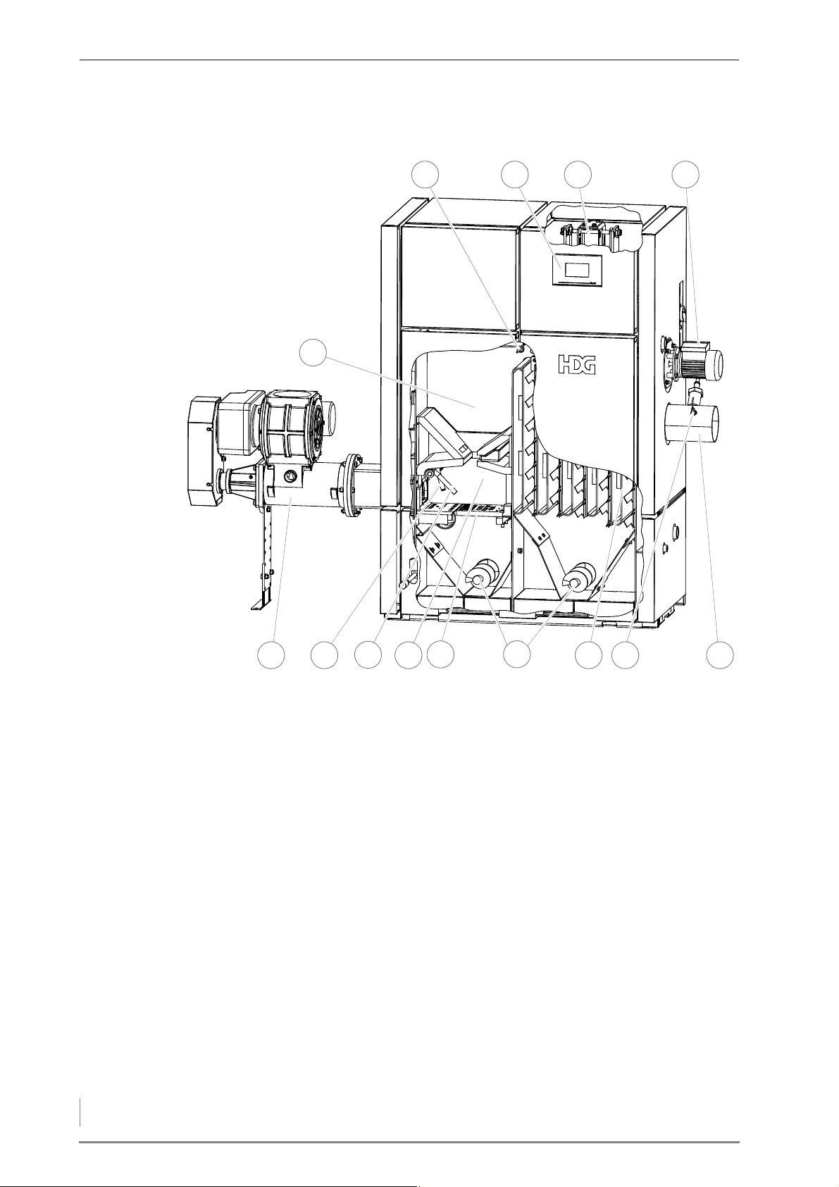
HDG Compact 25/35 front side . . . . . . . . . . . . . . . . . . . . . . . . . . . . . . . . . . . . . . . . . . . .16
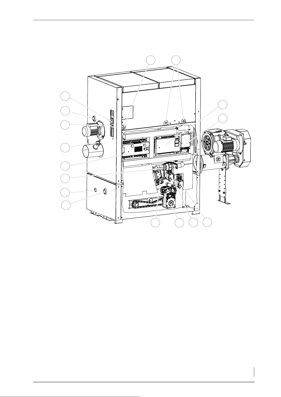
HDG Compact 25/35 back side . . . . . . . . . . . . . . . . . . . . . . . . . . . . . . . . . . . . . . . . . . . .17
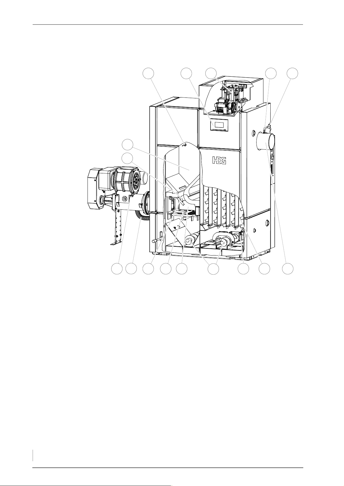
HDG Compact 45/50/65/80 front side. . . . . . . . . . . . . . . . . . . . . . . . . . . . . . . . . . . . . .18
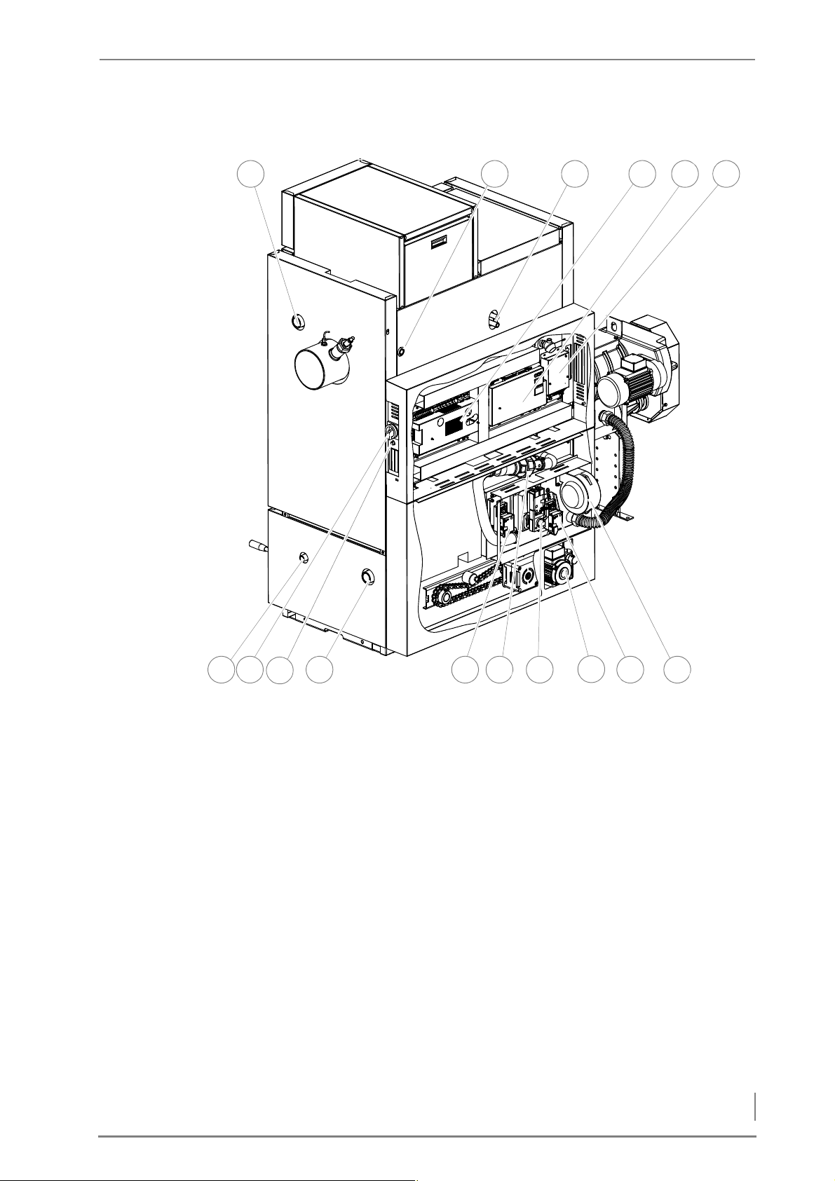
HDG Compact 45/50/65/80 back side . . . . . . . . . . . . . . . . . . . . . . . . . . . . . . . . . . . . .19
Overview of heating system . . . . . . . . . . . . . . . . . . . . . . . . . . . . . . . . . . . . . . . . . . . . . . .20
Combustion process . . . . . . . . . . . . . . . . . . . . . . . . . . . . . . . . . . . . . . . . . . . . . . . . . . . . . .21
Boiler and weather-compensated heating control HDG Control . . . . . . . . . . . .22
HDG Compact 25/35 . . . . . . . . . . . . . . . . . . . . . . . . . . . . . . . . . . . . . . . . . . . . . . . . . . . . . .23
HDG Compact 45/50/65/80 . . . . . . . . . . . . . . . . . . . . . . . . . . . . . . . . . . . . . . . . . . . . . . .24
Wood chips. . . . . . . . . . . . . . . . . . . . . . . . . . . . . . . . . . . . . . . . . . . . . . . . . . . . . . . . . . . . . . .25
Wood pellets . . . . . . . . . . . . . . . . . . . . . . . . . . . . . . . . . . . . . . . . . . . . . . . . . . . . . . . . . . . . .27
Pressed wood briquettes. . . . . . . . . . . . . . . . . . . . . . . . . . . . . . . . . . . . . . . . . . . . . . . . . .28
Recommended fuel . . . . . . . . . . . . . . . . . . . . . . . . . . . . . . . . . . . . . . . . . . . . . . . . . . . . . . .28
Permitted fuel in accordance with 1st Federal Emission Control Ordinance
(Germany) . . . . . . . . . . . . . . . . . . . . . . . . . . . . . . . . . . . . . . . . . . . . . . . . . . . . . . . . . . . . . . . .28
Nominal thermal value depending on water content. . . . . . . . . . . . . . . . . . . . . . .29
4 Planning and installation . . . . . . . . . . . . . . . . . . . . . . . . . . . . . . . . . . . . . . . . . . . . . . . . . . .30
4.1 Dimensions . . . . . . . . . . . . . . . . . . . . . . . . . . . . . . . . . . . . . . . . . . . . . . . . . . . . . . . . . . . . . . . .30
Flue gas pipe side HDG Compact 25 - 80 . . . . . . . . . . . . . . . . . . . . . . . . . . . . . . . . . . .30
HDG Compact 25 - 80 back side . . . . . . . . . . . . . . . . . . . . . . . . . . . . . . . . . . . . . . . . . . .31
4.2 Structural requirements . . . . . . . . . . . . . . . . . . . . . . . . . . . . . . . . . . . . . . . . . . . . . . . . . . . .32
Required room sizes and minimum clearances . . . . . . . . . . . . . . . . . . . . . . . . . . . . .32
Boiler installation site/boiler room. . . . . . . . . . . . . . . . . . . . . . . . . . . . . . . . . . . . . . . . .32
3
Page 4

Operation Manual HDG Compact 25 - 80 - Content
Fuel storage . . . . . . . . . . . . . . . . . . . . . . . . . . . . . . . . . . . . . . . . . . . . . . . . . . . . . . . . . . . . . 33
4.3 Connections. . . . . . . . . . . . . . . . . . . . . . . . . . . . . . . . . . . . . . . . . . . . . . . . . . . . . . . . . . . . . . . 34
Chimney. . . . . . . . . . . . . . . . . . . . . . . . . . . . . . . . . . . . . . . . . . . . . . . . . . . . . . . . . . . . . . . . . 34
Electrical system . . . . . . . . . . . . . . . . . . . . . . . . . . . . . . . . . . . . . . . . . . . . . . . . . . . . . . . . . 36
Water . . . . . . . . . . . . . . . . . . . . . . . . . . . . . . . . . . . . . . . . . . . . . . . . . . . . . . . . . . . . . . . . . . . 36
4.4 Scope of delivery . . . . . . . . . . . . . . . . . . . . . . . . . . . . . . . . . . . . . . . . . . . . . . . . . . . . . . . . . . 38
4.5 Installing the heating system . . . . . . . . . . . . . . . . . . . . . . . . . . . . . . . . . . . . . . . . . . . . . . 39
Installing the boiler . . . . . . . . . . . . . . . . . . . . . . . . . . . . . . . . . . . . . . . . . . . . . . . . . . . . . . 40
Installing the combustion fan . . . . . . . . . . . . . . . . . . . . . . . . . . . . . . . . . . . . . . . . . . . . 42
Installing the manual ash removal . . . . . . . . . . . . . . . . . . . . . . . . . . . . . . . . . . . . . . . . 43
Installing the automatic ash removal system
HDG Compact 25/35 . . . . . . . . . . . . . . . . . . . . . . . . . . . . . . . . . . . . . . . . . . . . . . . . . . . . . 44
Installing the automatic ash removal system
HDG Compact 45/50/65. . . . . . . . . . . . . . . . . . . . . . . . . . . . . . . . . . . . . . . . . . . . . . . . . . 47
Installing the heat exchanger cleaner . . . . . . . . . . . . . . . . . . . . . . . . . . . . . . . . . . . . . 50
Installing the feeding system and pressure equalisation hose. . . . . . . . . . . . . . 53
Installing the cladding HDG Compact 25/35 . . . . . . . . . . . . . . . . . . . . . . . . . . . . . . 55
Installing the cladding HDG Compact 45/50/65/80 . . . . . . . . . . . . . . . . . . . . . . . 62
Installing the flue gas temperature sensor and lambda sensor . . . . . . . . . . . . 70
Attaching the pressure equalisation hose . . . . . . . . . . . . . . . . . . . . . . . . . . . . . . . . . 71
Wiring the modules . . . . . . . . . . . . . . . . . . . . . . . . . . . . . . . . . . . . . . . . . . . . . . . . . . . . . . 72
Installing and adjusting the ash containers. . . . . . . . . . . . . . . . . . . . . . . . . . . . . . . . 72
Connecting the chimney . . . . . . . . . . . . . . . . . . . . . . . . . . . . . . . . . . . . . . . . . . . . . . . . . 73
4.6 Delivery system . . . . . . . . . . . . . . . . . . . . . . . . . . . . . . . . . . . . . . . . . . . . . . . . . . . . . . . . . . . 74
4.7 Electrical system. . . . . . . . . . . . . . . . . . . . . . . . . . . . . . . . . . . . . . . . . . . . . . . . . . . . . . . . . . . 74
4.8 Water . . . . . . . . . . . . . . . . . . . . . . . . . . . . . . . . . . . . . . . . . . . . . . . . . . . . . . . . . . . . . . . . . . . . . 74
4.9 Thermal safety device . . . . . . . . . . . . . . . . . . . . . . . . . . . . . . . . . . . . . . . . . . . . . . . . . . . . . 75
5 Commissioning the system . . . . . . . . . . . . . . . . . . . . . . . . . . . . . . . . . . . . . . . . . . . . . . . . 77
5.1 Requirements . . . . . . . . . . . . . . . . . . . . . . . . . . . . . . . . . . . . . . . . . . . . . . . . . . . . . . . . . . . . . 77
5.2 Procedure . . . . . . . . . . . . . . . . . . . . . . . . . . . . . . . . . . . . . . . . . . . . . . . . . . . . . . . . . . . . . . . . . 78
6 Using the heating system . . . . . . . . . . . . . . . . . . . . . . . . . . . . . . . . . . . . . . . . . . . . . . . . . . 79
6.1 Control unit HDG Control . . . . . . . . . . . . . . . . . . . . . . . . . . . . . . . . . . . . . . . . . . . . . . . . . . 79
6.2 Filling the fuel storage room . . . . . . . . . . . . . . . . . . . . . . . . . . . . . . . . . . . . . . . . . . . . . . . 79
Requirements. . . . . . . . . . . . . . . . . . . . . . . . . . . . . . . . . . . . . . . . . . . . . . . . . . . . . . . . . . . . 79
Procedure for filling with wood chips . . . . . . . . . . . . . . . . . . . . . . . . . . . . . . . . . . . . . 79
Procedure for filling with pellets. . . . . . . . . . . . . . . . . . . . . . . . . . . . . . . . . . . . . . . . . . 80
6.3 Performing a chimney sweep measurement. . . . . . . . . . . . . . . . . . . . . . . . . . . . . . . . 80
6.4 Switching off the heating system for repair work . . . . . . . . . . . . . . . . . . . . . . . . . . . 80
7 Cleaning and servicing the heating system . . . . . . . . . . . . . . . . . . . . . . . . . . . . . . . . . 81
7.1 Cleaning and servicing schedule . . . . . . . . . . . . . . . . . . . . . . . . . . . . . . . . . . . . . . . . . . . 81
7.2 Requirements . . . . . . . . . . . . . . . . . . . . . . . . . . . . . . . . . . . . . . . . . . . . . . . . . . . . . . . . . . . . . 82
Generally applicable safety instructions. . . . . . . . . . . . . . . . . . . . . . . . . . . . . . . . . . . 82
Cleaning tools . . . . . . . . . . . . . . . . . . . . . . . . . . . . . . . . . . . . . . . . . . . . . . . . . . . . . . . . . . . 83
Cleaning the tilting grate . . . . . . . . . . . . . . . . . . . . . . . . . . . . . . . . . . . . . . . . . . . . . . . . 83
4
Page 5

Operation Manual HDG Compact 25 - 80 - Content
Checking and emptying the ash container . . . . . . . . . . . . . . . . . . . . . . . . . . . . . . . . .84
Lubricating the feeding system. . . . . . . . . . . . . . . . . . . . . . . . . . . . . . . . . . . . . . . . . . . .87
Lubricate heat exchanger cleaning . . . . . . . . . . . . . . . . . . . . . . . . . . . . . . . . . . . . . . . .87
Checking the drive chains . . . . . . . . . . . . . . . . . . . . . . . . . . . . . . . . . . . . . . . . . . . . . . . . .88
Cleaning the cleaning shaft and turbulators . . . . . . . . . . . . . . . . . . . . . . . . . . . . . . .91
Checking and cleaning the lambda sensor . . . . . . . . . . . . . . . . . . . . . . . . . . . . . . . . .93
Cleaning the flue gas pipe. . . . . . . . . . . . . . . . . . . . . . . . . . . . . . . . . . . . . . . . . . . . . . . . .94
Cleaning the ash removal system . . . . . . . . . . . . . . . . . . . . . . . . . . . . . . . . . . . . . . . . .95
Cleaning the flue gas temperature sensor . . . . . . . . . . . . . . . . . . . . . . . . . . . . . . . . .96
Cleaning the ignition fan . . . . . . . . . . . . . . . . . . . . . . . . . . . . . . . . . . . . . . . . . . . . . . . . . .96
Cleaning the flue gas fan . . . . . . . . . . . . . . . . . . . . . . . . . . . . . . . . . . . . . . . . . . . . . . . . . .98
Cleaning the pressure equalisation hose. . . . . . . . . . . . . . . . . . . . . . . . . . . . . . . . . . .99
Cleaning and lubricating the overfill lever . . . . . . . . . . . . . . . . . . . . . . . . . . . . . . . . .99
Checking the fuel storage . . . . . . . . . . . . . . . . . . . . . . . . . . . . . . . . . . . . . . . . . . . . . . . 101
8 Notes on dismantling and disposal. . . . . . . . . . . . . . . . . . . . . . . . . . . . . . . . . . . . . . . . 102
8.1 Dismantling . . . . . . . . . . . . . . . . . . . . . . . . . . . . . . . . . . . . . . . . . . . . . . . . . . . . . . . . . . . . . . 102
8.2 Disposal. . . . . . . . . . . . . . . . . . . . . . . . . . . . . . . . . . . . . . . . . . . . . . . . . . . . . . . . . . . . . . . . . . 103
9 Declaration of Conformity . . . . . . . . . . . . . . . . . . . . . . . . . . . . . . . . . . . . . . . . . . . . . . . . 104
10 Index . . . . . . . . . . . . . . . . . . . . . . . . . . . . . . . . . . . . . . . . . . . . . . . . . . . . . . . . . . . . . . . . . . . . 105
5
Page 6

Operation Manual HDG Compact 25 - 80 - Content
6
Page 7

1 Notes on this manual – Introduction
1 Notes on this manual
1.1 Introduction
EASY AND SAFE OPERATION This Operating manual contains important instructions on the
• HDG Compact 25/35
• HDG Compact 45/50/65
• HDG Compact 80
and how to operate it properly and safely. Following these instructions helps to avoid dangers, prevent repair costs and downtimes,
maintain reliability and extend the life expectancy of the heating
system.
R
EADING THE OPERATING
MANUAL
T
ECHNICAL CHANGES We continuously develop and improve our boilers. The information
This Operating manual must be read and applied by everyone who
operates or works on the heating system HDG Compact 25 - 80.
in this edition was correct at the time of going to press.
All details in these instructions on standards, regulations and work-
sheets should be checked before use and should be compared with
the regulations applying locally at the site where the system is installed.
We reserve the right to make changes which may then differ from the
technical details and illustrations in this Operating manual.
C
OPYRIGHT Written permission is required from HDG Bavaria GmbH for re-
printing, storage in a data-processing system or transmission by electronic, mechanical, photographic or any other means, and for copies
or translations of this publication, in whole or in part.
G
UARANTEE The terms and conditions of the guarantee of your (central-heating)
boiler can be found in the enclosed information sheet.
S
YMBOLS USED In this Operating manual, the following designations and symbols
are used for particularly important information:
1. Instructions to the operator
✓ Result of the action described
✎ Cross reference for more explanation
• List
–List
7
Page 8
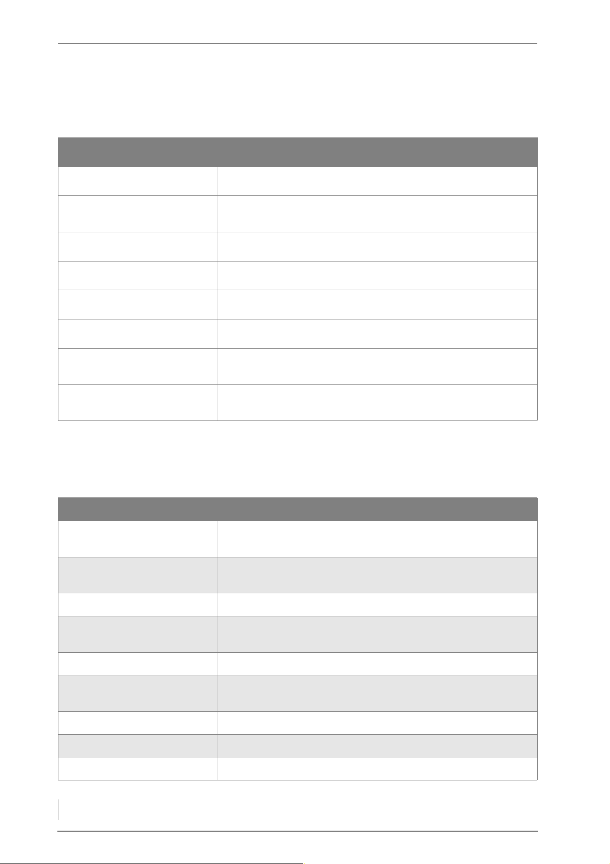
1 Notes on this manual – Structure of the Operating manual
1.2 Structure of the Operating manual
The Operating manual is structured as follows:
Chapter This explains ...
1 Notes on this manual ... how to use this Operating manual.
2 Safety notes ... everything on the subject of safety that you should consider
when using the heating system.
3 Mode of operation ... the structure and all of the features of the heating system.
4 Planning and installation . . . how to properly plan and install the heating system.
5 Commissioning the system ... how the heating system is put into initial service.
6 Using the heating system ... how to properly operate the heating system.
7 Cleaning and servicing the
heating system
8 Notes on dismantling and
disposal
... how to clean the heating system and who is responsible for its
maintenance.
... what has to be considered when dismantling and disposing of
the heating system.
Table 1/1 - Structure of the Operating manual
1.3 Glossary
Term Explanation
Actuator This is a component which carries out a certain function in the
heating system, e.g. the stoker auger.
Ash removal augers These transport the combustion chamber ash and fly ash into the
exterior ash containers.
Ash removal motor Drives the ash removal augers.
Delivery system Fuel transport system conveys the fuel from the fuel storage room
to the dosing unit and to the intermediate container.
Display Display on the HDG Control control unit
Feeding system Feeds the fuel to the boiler by means of the rotary feeder and the
stoker auger.
Grate tilting motor Electric motor which moves the tilting grate.
HDG Compact 25 - 80 Boiler for burning wood chips, shavings and wood pellets.
HDG Control Boiler and weather-compensated heating control.
Table 1/2 - Glossary
8
HDG Compact 25 - 80 - Version 2 - en © HDG Bavaria GmbH October 2007
Page 9

1 Notes on this manual – Glossary
Term Explanation
Heating system Comprised of boiler and corresponding accessories.
Main switch Switches off the mains supply to the entire heating system.
Rotary feeder Part of the feeding system - separates the combustion chamber
from the silo and transport unit and acts as back-burn protection.
Sensor Records certain parameters (temperature, fill level) and forwards
them to the control for analysis.
Stoker auger Carries the fuel from the rotary feeder into the combustion cham-
ber.
Wood chips, B1 Machine-chopped wood with a water content of between 15 to 35
percent (in accordance with EN 303-5).
Table 1/2 - Glossary
9
Page 10

2 Safety instructions – Intended use
2 Safety instructions
2.1 Intended use
BASIC SYSTEM DESIGN PRINCIPLES
BASIC PRINCIPLES The heating system was built using state-of-the-art technology and
conforms to recognised safety regulations. Nevertheless, there is still
a risk of injury or death to users or bystanders, and of adverse effects
upon the heating system or upon other material goods.
Have your specialist heating company provide you with detailed instructions on the operation of the heating system.
U
SING THE HEATING SYSTEM Only use the heating system when it is in perfect condition. Use it
properly, as intended, be aware of safety and hazards, and observe
the Operating manual. Have any faults which could impair safety
fixed immediately.
This device can be used by children over 8 years old and people with
reduced physical, sensory or mental capabilities or a lack of experience and knowledge, provided they are supervised or have been instructed on the safe use of the device and understand the resulting
risks. Children may not play with the device. Cleaning and user maintenance must not be carried out by children without supervision.
BASIC PRINCIPLES FOR THE CONTENT OF THE OPERATING MANUAL
SCOPE The content of this operating manual is intended exclusively for the
planning, installation and operation of the HDG Compact 25 - 80
heating systems. Any further implementation of applicable standards, for example with regard to the installation of the heating
system (pipework, etc.) is not part of this operating manual. HDG Bavaria does not assume any liability for this.
PROPER AND IMPROPER MANNER OF OPERATION
PURPOSE OF THE HEATING
SYSTEM
The HDG Compact 25 - 80 heating system is designed for the
standard use of burning wood fuel products made from untreated
wood in the form of wood chips, shavings and pellets for the purpose
of warm water heating.
Any other application is considered improper use. The manufacturer
will accept no liability for any damage resulting from improper use.
The operator bears sole responsibility in such cases.
Proper use includes adherence to the installation, operation and
maintenance requirements specified by the manufacturer.
10
HDG Compact 25 - 80 - Version 2 - en © HDG Bavaria GmbH 10/2007
Page 11
2 Safety instructions – Residual risks
Modification of the specified operating values will affect the heating
system’s control programme and could lead to malfunctions. Only
trained maintenance and operating personnel may undertake modifications to the operating values.
The use of materials with other technical burning characteristics requires comprehensive modification of the control parameters by
qualified specialists.
For more information on fuel, see chapter “3 Mode of operation”,
section “3.4 Fuel quality requirements”.
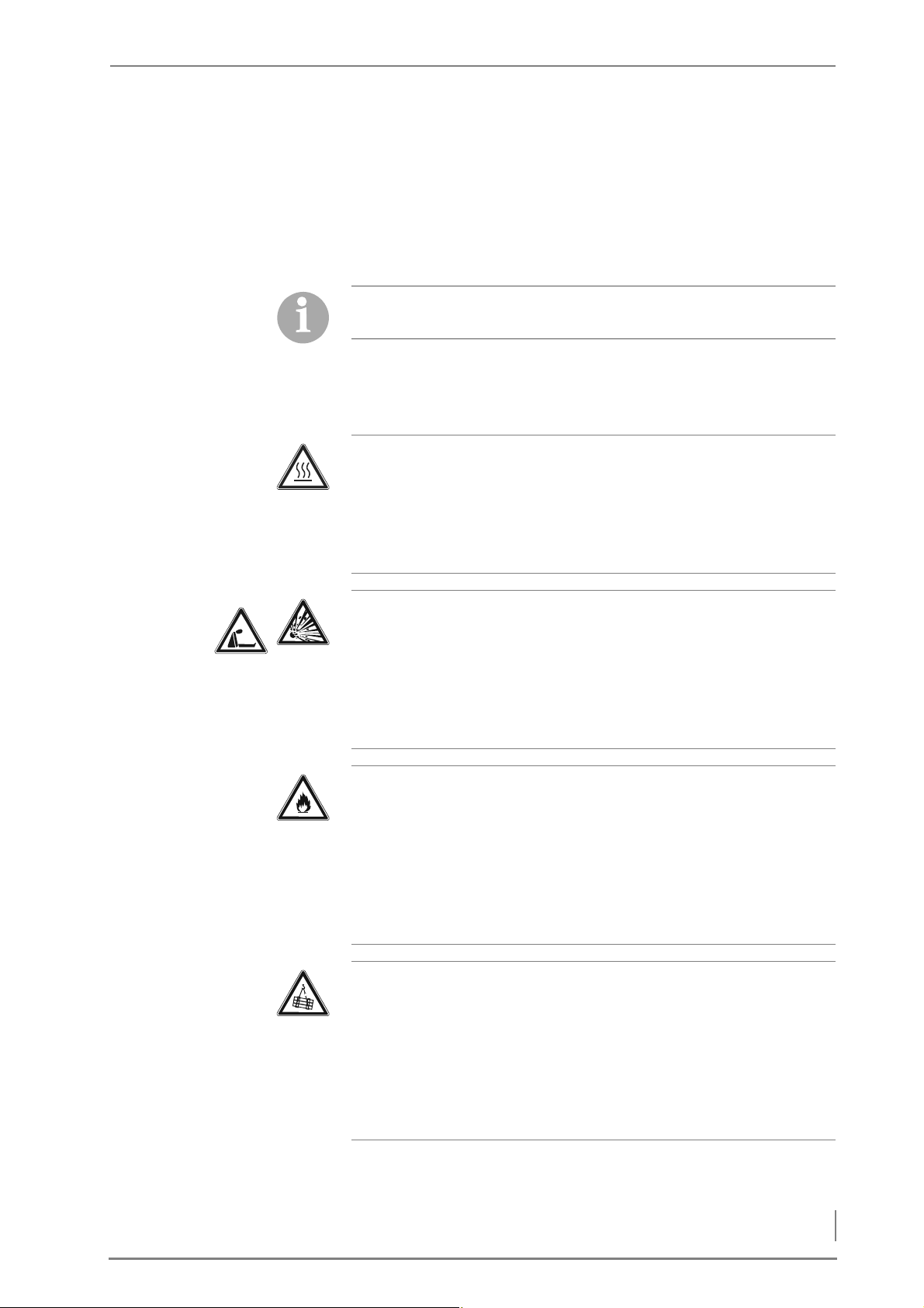
2.2 Residual risks
Despite all precautions, the following residual risks remain:
Caution!
Hot surfaces
Contact with the hot surfaces of the boiler can lead to burns.
Wait until the boiler has cooled down before touching non-insu-
lated components.
Danger!
Danger of asphyxiation and explosion from carbon monoxide
When the boiler is in operation, carbon monoxide escaping from
open cleaning or inspection hatches can cause asphyxiation or explosions.
Do not leave these open any longer than necessary.
Warning!
Danger of fire
Opening doors and lids to hot combustion residues can pose the
danger of fires.
Keep the openings closed during operation, and when performing
cleaning work, allow the combustion residues to cool down before
you place them in a fireproof container.
Warning!
Danger from suspended loads
The boiler weighs over 700 kg. If the boiler is dropped during trans-
port, persons can be seriously injured and the boiler can be damaged.
Make sure that you use appropriate lifting gear when placing the
boiler.
11
© HDG Bavaria GmbH 10/2007 HDG Compact 25 - 80 - Version 2 - en
Page 12
2 Safety instructions – Warnings and safety symbols used
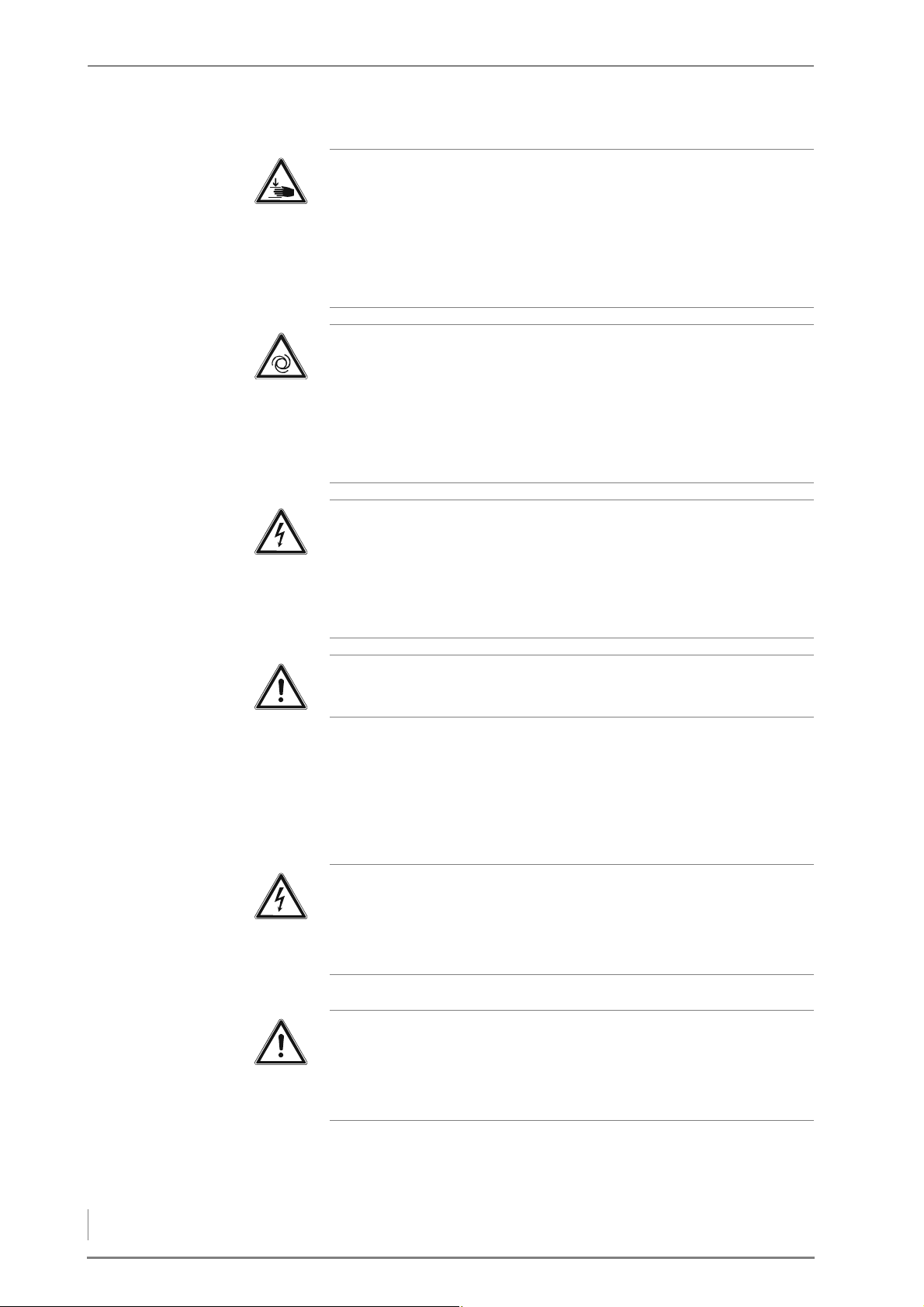
Warning!
Danger of injury
The cleaning shaft lid is very heavy and can fall shut. Hands and
arms could thereby be crushed.
Take care not to bump into the opened cleaning shaft lid and cause
it to fall shut.
Warning!
Risk of injury from automatically driven components
When working on the automatic ash removal or on the automatic
heat exchanger cleaner, hands and arms could be injured.
Turn off the main switch when performing any work on these com-
ponents.
Danger!
Dangerous electrical current or voltage
The circuit boards and electrical components carry current.
Have work on electrical components performed only by a qualified
electrician and turn the main switch off.
Warning!
The boiler is under pressure.
2.3 Warnings and safety symbols used
The following warnings and safety symbols are used in this Operating manual :
Danger!
Dangerous electrical current or voltage
Work in areas marked with this symbol may only be performed by a
qualified electrician.
Warning!
Hazardous area
Working in areas marked with this symbol can lead to serious inju-
ries or to extensive material damage.
12
HDG Compact 25 - 80 - Version 2 - en © HDG Bavaria GmbH 10/2007
Page 13
2 Safety instructions – Warnings and safety symbols used
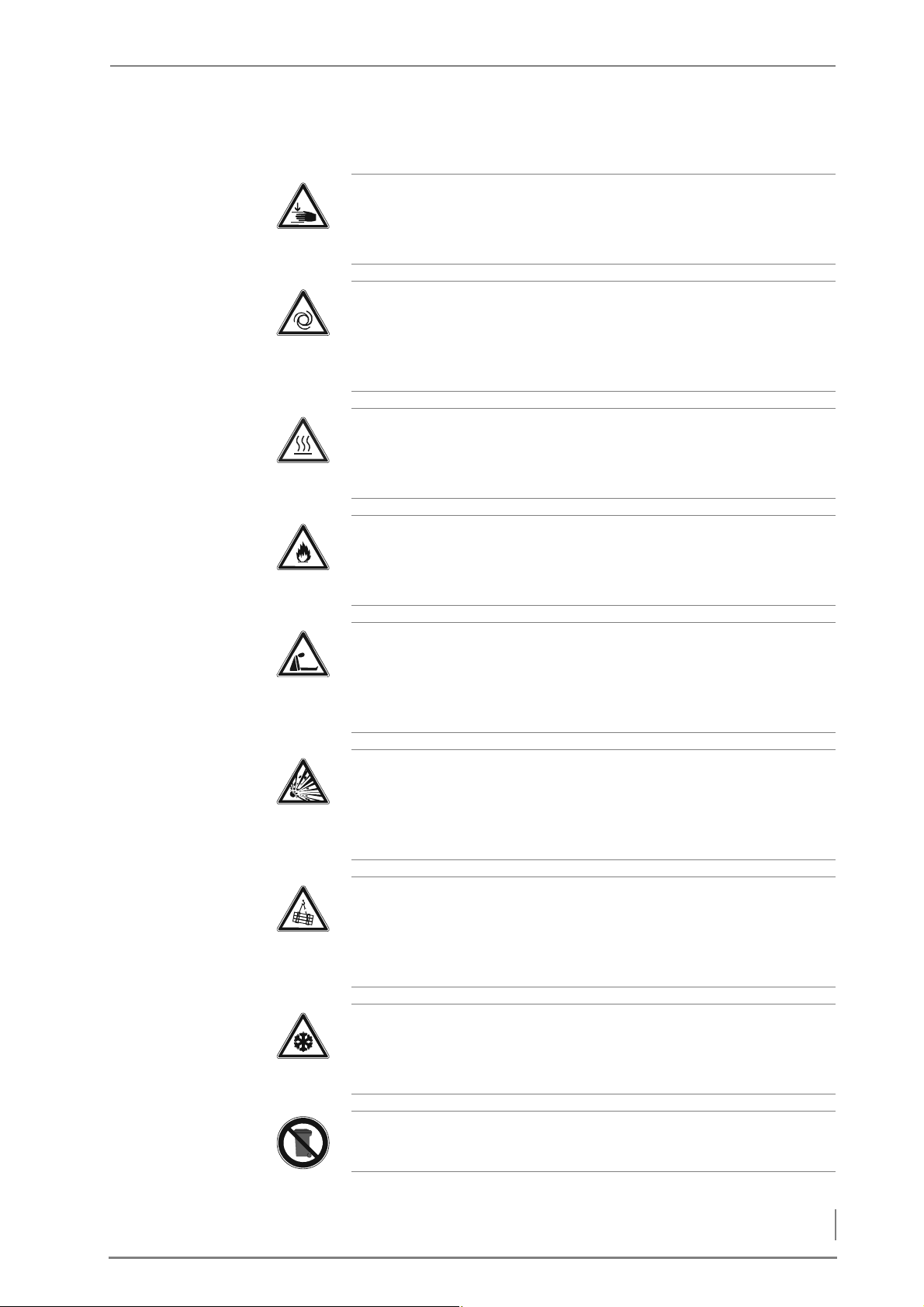
Warning!
Hand injuries can occur
Working in areas marked with this symbol can lead to hand injuries.
Warning!
Automatic start-up
Working in areas marked with this symbol can lead to injuries due
to automatic start-up.
Caution!
Hot surfaces
Working in areas marked with this symbol can lead to burns.
Warning!
Danger of fire
Working in areas marked with this symbol can lead to a fire.
Danger!
Danger of asphyxiation due to lack of oxygen
When working in areas marked with this symbol, there is a danger
of asphyxiation due to high concentrations of carbon monoxide.
Danger!
Danger of explosion
When working in areas marked with this symbol, there is a danger
of explosion due to high concentrations of carbon monoxide.
Warning!
Suspended loads
When working in areas marked with this symbol, there is a danger
of falling objects.
Important!
Frost danger
Only install the heating system in a frost-proof room.
Instructions regarding disposal
13
© HDG Bavaria GmbH 10/2007 HDG Compact 25 - 80 - Version 2 - en
Page 14

2 Safety instructions – Duty of information
Additional information for the operator
2.4 Duty of information
READING THE OPERATING
MANUAL
Every person performing any tasks on the system is required to read
the Operating manual prior to beginning work, particularly the
chapter “2 Safety instructions”.
This is especially important for persons who only occasionally work
on the heating system, for example when cleaning or servicing it.
The Operating manual must always be kept readily accessible at the
place where heating system is installed.
14
HDG Compact 25 - 80 - Version 2 - en © HDG Bavaria GmbH 10/2007
Page 15

3 Mode of operation – Overview
3 Mode of operation
3.1 Overview
The version of the HDG Compact 25 - 80 heating system installed depends on whether the feeding system is to be fitted
• on the right-hand side or
• on the left-hand
side.
The heating system is equipped as standard with an automatic heat
exchanger cleaning system.
The HDG Compact 80 is already equipped as standard with a de-
ashing system for automatic ash removal to external containers. This
component is also optionally available for the HDG Compact 25 - 65.
When selecting the feeding unit for the HDG Compact 25 - 80
heating system, you can choose between the following:
• TBZ 150 for feeding wood chips, shavings and pellets.
• Pellet suction system with TBZ 90 for feeding pellets.
The HDG Compact 25 - 80 heating system can also be equipped with
the following delivery systems:
• FRA flexi blade delivery system
• Hinged arm delivery system
• Walking floor delivery system
• Inclined auger delivery system
• Pellet delivery system
✎ This Operating manual - unless otherwise specified - depicts and
describes the fully equipped version with the TBZ150 feeding
system on the left-hand side.
15
Page 16
3 Mode of operation – Overview
HDG COMPACT 25/35 FRONT SIDE
12 6
432
14
13 5
1
10 7
11
9
8
Figure 3/1 - Front side of the HDG Compact 25/35 boiler
1 Combustion chamber temperature sensor
2. Control unit for HDG Control Touch
3 Heat exchanger cleaner drive
4Flue gas fan
5 Flue gas pipe connection
6 Flue gas temperature sensor
7 Heat exchanger surfaces with cleaning turbulators in between
8 Ash removal augers
9Tilting grate
10 Combustion chamber primary burning
11 Level indicator
12 Ignition pipe
13 Feeding system
14 Combustion chamber secondary burning
16
Page 17
3 Mode of operation – Overview
HDG COMPACT 25/35 BACK SIDE
8
7
5
4
3
21
9
11
12
13
16
15
6
10
14
Figure 3/2 - HDG Compact 25/35 boiler back side
1 Connection of immersion sleeve for thermal safety device (DN 15,
inside thread)
2 Safety heat exchanger connections (DN 15, outside thread)
3Drive module
4Expansion module EM4 (optional)
5 Actuator primary air
6 Actuator secondary air
7 Ash removal motor
8 Grate tilting motor
9 Boiler return connection (DN 32 IG)
10 Filling/draining connection (DN 15 IG)
11 Ignition fan
12 Central module
13 Lambda sensor
14 STL release button
15 Boiler supply connection (DN 32 IG)
16 Main switch
17
Page 18
3 Mode of operation – Overview
HDG COMPACT 45/50/65/80 FRONT SIDE
2
7 6
53
12
15
14
1 4
1011 8
16
9
13
Figure 3/3 - Front side of the HDG Compact 45/50/65/80 boiler
1 Combustion chamber temperature sensor
2 Control unit for HDG Control Touch
3 Heat exchanger cleaner drive
4 Flue gas temperature sensor
5Lambda sensor
6 Flue gas pipe connection
7 Heat exchanger surfaces with cleaning turbulators in between
8 Ash walking floor delivery system
9 Ash removal augers
10 Combustion chamber primary burning
11 Tilting grate
12 Level indicator
13 Pressure equalisation hose
14 Feeding system
15 Ignition pipe
16 Combustion chamber secondary burning
18
Page 19
3 Mode of operation – Overview
HDG COMPACT 45/50/65/80 BACK SIDE
1
8 7
42 5
16
3 6
15 13 101112
14
9
Figure 3/4 - HDG Compact 45/50/65/80 boiler back side
1 Boiler return connection (DN 32 IG and DN 40 IG)
2 Immersion sensor connection for thermal safety device
3 Safety heat exchanger connections
4Central module
5Drive module
6Expansion module EM4 (optional)
7Combustion air fan
8 Actuator primary air
9 Ash removal motor
10 Grate tilting motor
11 Ignition fan
12 Actuator, secondary air
13 Boiler return connection (DN 32 IG and DN 40 IG)
14 STL release button
15 Main switch
16 Filling/draining connection (DN 15 IG)
19
Page 20
3 Mode of operation – Functional description
3.2 Functional description
1 2 3
OVERVIEW OF HEATING SYSTEM
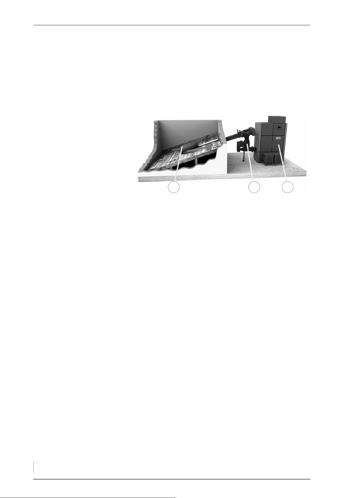
The HDG Compact 25 - 80 heating system may contain the following
components:
Figure 3/5 - Overview
1 Delivery system
2Feeding system
3 HDG Compact 25 - 80 boiler with HDG Control
20
Page 21
3 Mode of operation – Functional description
COMBUSTION PROCESS
78
21 4
5
3
6
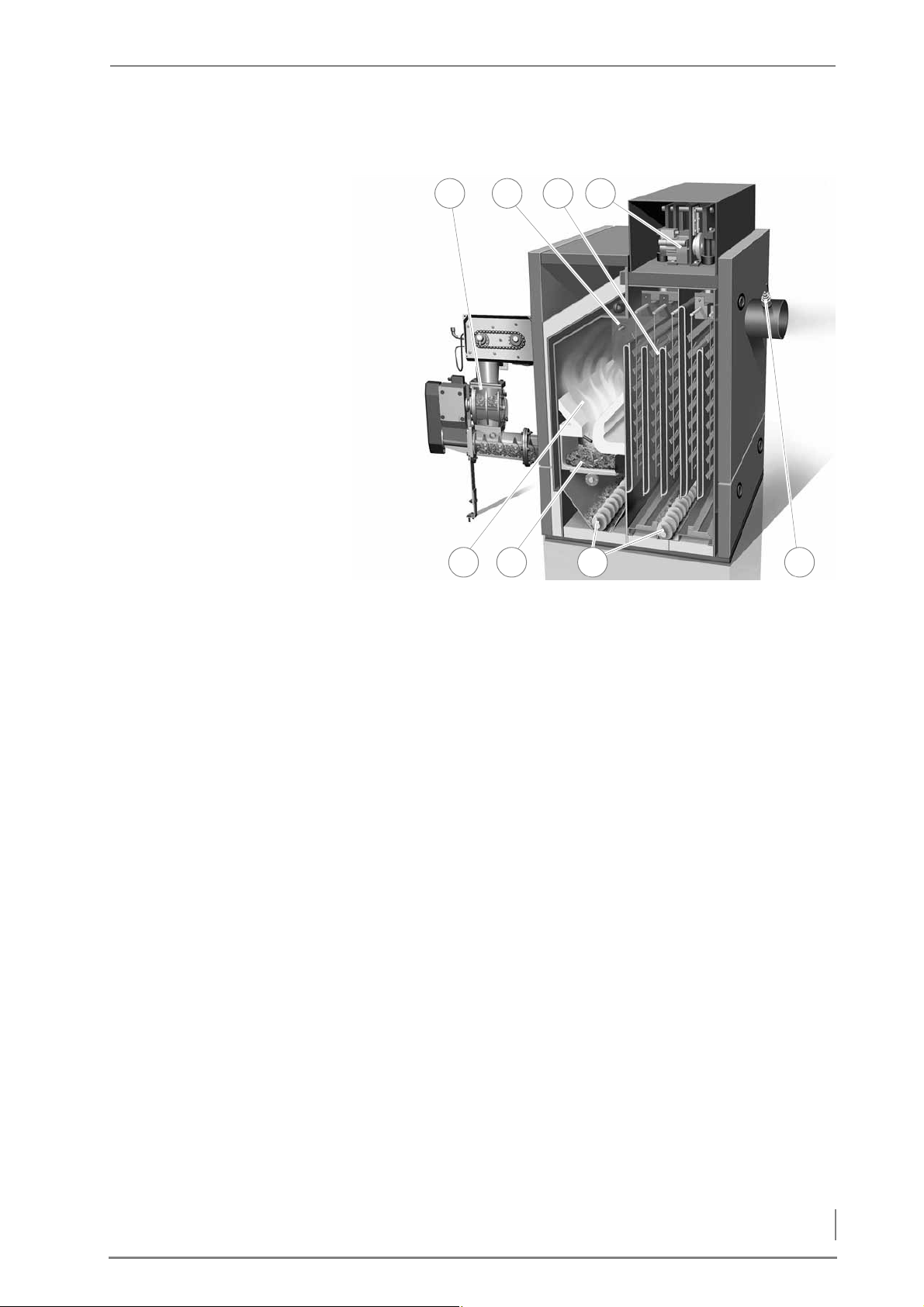
Figure 3/6 - HDG Compact 45/50/65/80 heating system
When there is a need for heat in the accumulator the HDG Compact
20 – 80 automatically starts the “first filling” by loading fuel from the
fuel store into the combustion chamber (8) via the feeding system
(1).
After completion of the “first filling” the electric ignitor produces hot
air which sets fire to the fuel in the combustion chamber (8). After this
“ignition” phase the “heating up” phase begins when the fuel is introduced to the combustion chamber at a gradually increasing predetermined rate.
Following the “heating up” phase the HDG Compact 25 – 80 goes
into “automatic control” where the amount of fuel, primary air and
secondary air is provided, based on the combustion requirements.
The ash produced during combustion is removed by tipping the
grate (7) at regular intervals. The automatic cleaning (4) removes the
lighter fly ash from the heat exchanger surfaces (3) periodically by
raising and lowering the turbulators.
The ash falls into either an ash pan in the base of the boiler or onto
ash removal augers (6) which extract the waste material into ash containers.
The amount of primary and secondary air introduced into the combustion chamber (8) is governed by primary and secondary servos,
and dictated by the control to maintain efficient combustion.
The Lambda sensor (5), boiler temperature, and combustion
chamber sensor (2) feed information back to the control to do the following:
– Continuously monitor firing
– Adapt the boiler to heat requirements
21
Page 22

3 Mode of operation – Functional description
– Minimise emissions
– Optimise boiler efficiency
BOILER AND WEATHER-COMPENSATED HEATING CONTROL HDG CONTROL
BOILER CONTROL The boiler control unit HDG Control is the electronic hub of the
boiler. It consists of the ready-to-use central and drive module and
control unit on the front of the boiler. Using the control unit, you can
regulate the boiler and call up information on the current process.
The fuel feeding (delivery, dosing and feeding) is also controlled by
the HDG Control.
H
EATING CIRCUIT CONTROL The HDG Control controls the entire energy management of the
heating system including the following, depending on the version:
• Accumulator management
• Weather-compensated heating circuits
• Domestic hot water heating
• Peak load boiler control
• District heating pumps
• Solar thermal system for hot water and support of the heating
system
✎ For the description of the boiler and weather-compensated
heating control HDG Control, refer to the “HDG Control” operating
manual.
22
Page 23
3 Mode of operation – Technical data
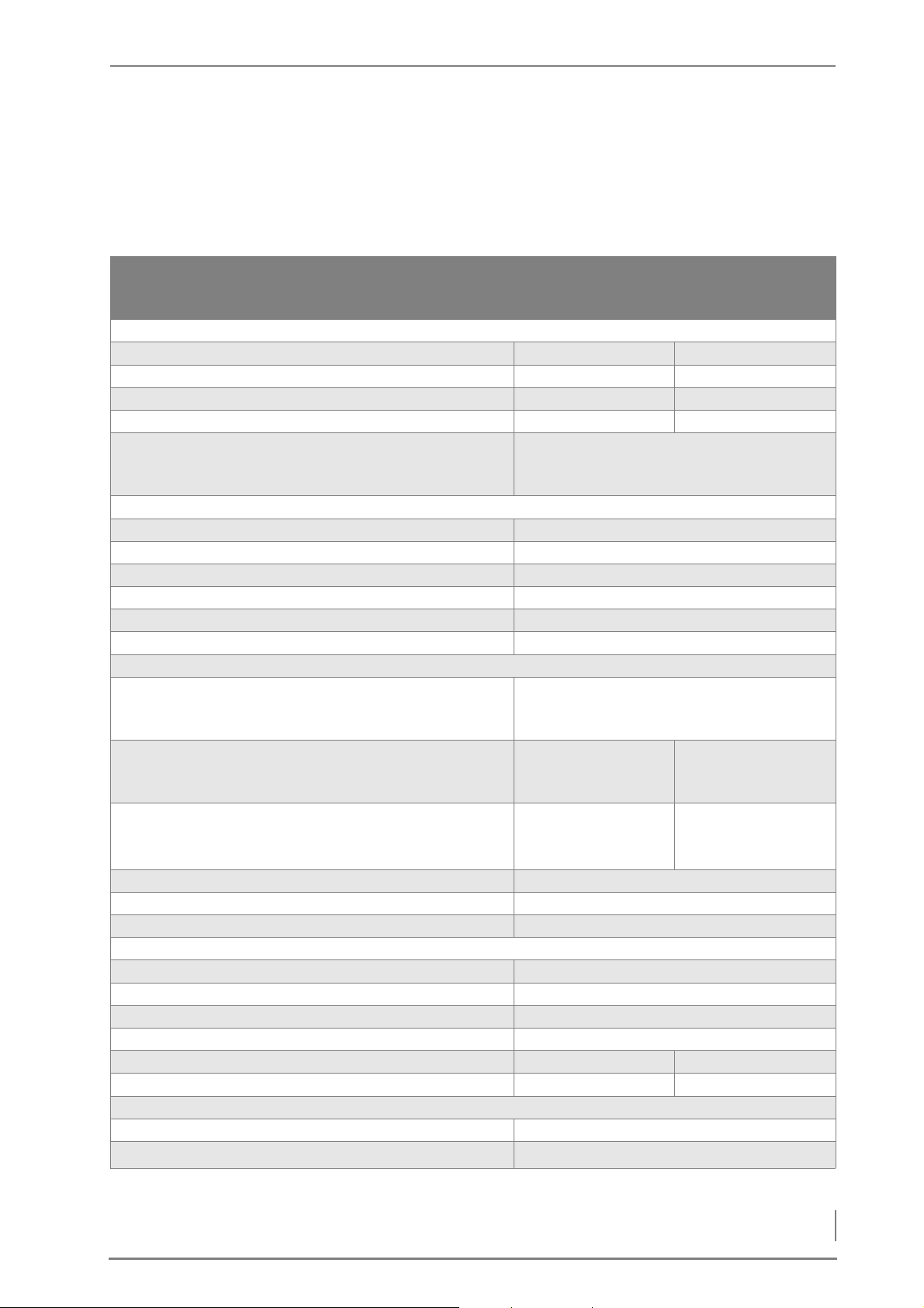
3.3 Technical data
HDG COMPACT 25/35
Boiler type
HDG
Compact 25
Wood chips / pellets
HDG
Compact 35
Wood chips / pellets
Performance data (measured according to DIN EN 303-5)
Nominal thermal power 31.0/26.0 kW 31.0/35.0 kW
Minimum thermal power 9.1/7.7 kW 9.1/7.7 kW
Boiler efficiency at nominal thermal power 93.2 / 92.0 % 93.2 / 90.7 %
Electrical power consumption at nom. thermal power 265/250 W 265/260 W
Electrical connection:
• Voltage/frequency
• Back-up fuse
230/400 V / 50 Hz
16 A
General boiler data
Boiler class 3
Maximum permissible operating pressure 3 bar
Maximum flow temperature* 95 °C
Minimum return temperature 60 °C
Water capacity 110 l
Weight 650 kg
Planning data for flue calculation (DIN EN 13384-1)
Flue gas temperature (Tw) at
• Nominal thermal power
• minimum thermal power
160 °C
110 °C
Flue gas mass flow at
• Nominal thermal power
• minimum thermal power
CO
content at
2
• Nominal thermal power
• minimum thermal power
0.0210 / 0.0170 kg/s
0.0070 kg/s
12.1 / 12.2 %
11.3 / 8.9 %
0.0210 / 0.0230 kg/s
0.0070 kg/s
12.1 / 12.5 %
11.3 / 8.9 %
Flue draught requirement (Pw) 7 Pa
Diameter of flue pipe connection 150 mm
Height at middle of the flue gas pipe connection 820 mm
Water-side connections
Supply and return connections (bushing) DN 32, inside thread
Safety heat exchanger connections (bushing) DN 15, outside thread
Connection for drain (bushing) DN 15, inside thread
Recommended pipe dimensions (minimum) DN 32
Water-side resistance at nominal thermal power, 10K 1400 Pa 2200 Pa
Water-side resistance at nominal thermal power, 20 K 400 Pa 600 Pa
Other information
Sound pressure level < 70 dB(A)
Min. Air inlet cross section
150 cm
Table 3/1 - Technical data
* maximum operating temperatures of up to 110 °C can also briefly occur.
2
23
Page 24
3 Mode of operation – Technical data
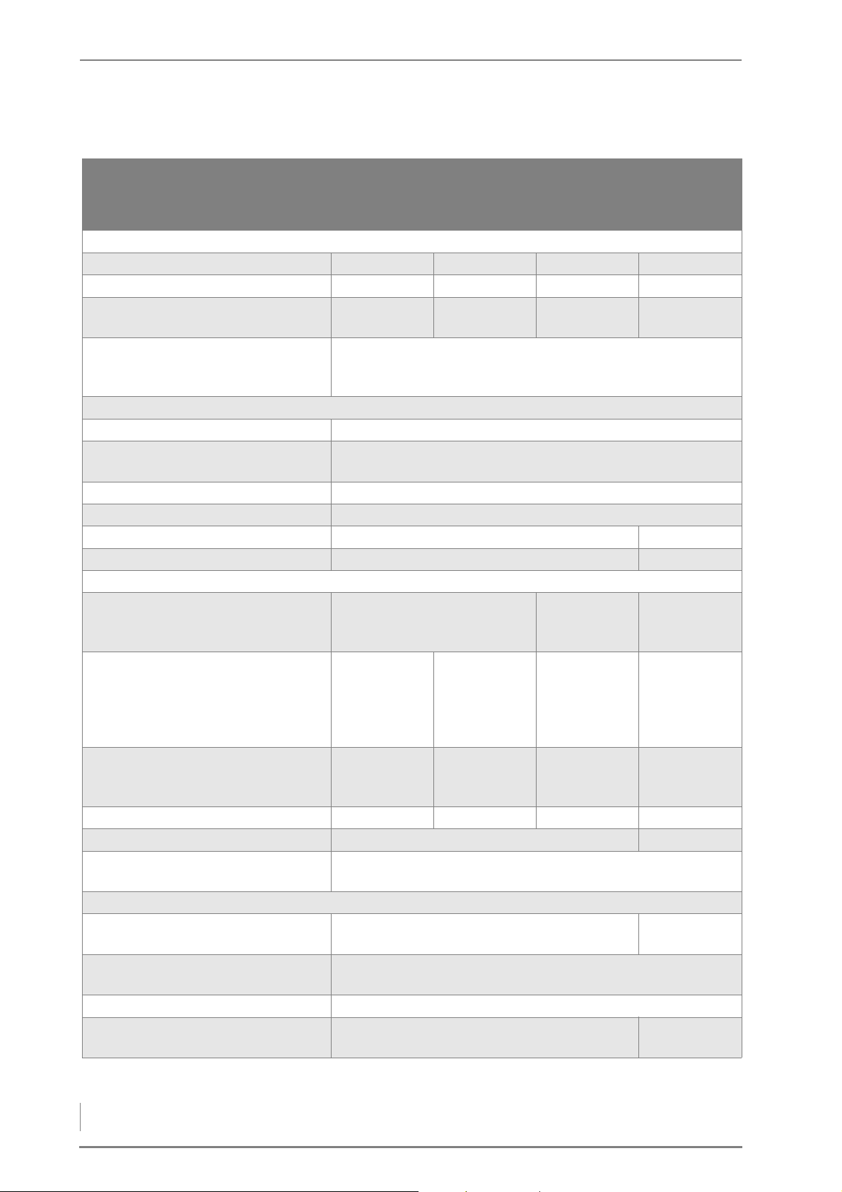
HDG COMPACT 45/50/65/80
Boiler type
HDG
Compact 45
Wood chips /
pellets
HDG
Compact 50
Wood chips /
pellets
HDG
Compact 65
Wood chips /
pellets
HDG
Compact 80
Wood chips /
pellets
Performance data (measured according to DIN EN 303-5)
Nominal thermal power 45.0 kW 50.0 kW 65.0 kW 80.0/85.0 kW
Minimum thermal power 13.5 kW 12.0/15.0 kW 12.0/15.0 kW 23.0/25.1 kW
Boiler efficiency at nominal thermal
92.0 / 91.8 % 91.7 / 91.8 % 91.9 / 92.6 % 92.2 / 93.7 %
power
Electrical connection:
• Voltage/frequency
• Back-up fuse
230/400 V / 50 Hz
16 A
General boiler data
Boiler class 3
Maximum permissible operating
3.0 bar
pressure
Maximum flow temperature* 95 °C
Minimum return temperature 60 °C
Water capacity 167 l 221 l
Weight 980 kg 1200 kg
Planning data for flue calculation (DIN EN 13384-1)
Flue gas temperature (Tw) at
• Nominal thermal power
• minimum thermal power
160 °C
105 °C
180 °C
110 °C
160 / 150 °C
105 °C
Flue gas mass flow at
• Nominal thermal power
• minimum thermal power
0.029/
0.026 kg/s
0.0125 kg/s
0.0326 kg/s
0.0125 kg/s
0.0414/
0.0375kg/s
0.0182/
0.0144kg/s
0.0520/
0.0440kg/s
0.0250/
0.0170kg/s
CO2 content at
• Nominal thermal power
• minimum thermal power
11.4 / 12.2 %
10.4 / 11.3 %
11.4 / 12.2 %
10.4 / 11.3 %
12.7 / 13.8 %
8.9 / 11.1 %
14.1 / 13.5 %
7.3 / 10.8 %
Flue draught requirement (Pw) 10 Pa 13 Pa 15 Pa 12 / 9* Pa
Diameter of flue pipe connection 180 mm 200 mm
Height at middle of the flue gas pipe
1280 mm
connection
Water-side connections
Supply and return connections
(bushing)
Safety heat exchanger connections
DN 32, inside thread DN 40, inside
thread
DN 15, outside thread
(bushing)
Connection for drain (bushing) DN 15, inside thread
Recommended pipe dimensions
(minimum)
Table 3/2 - Technical data
DN 32 DN 40
24
Page 25
3 Mode of operation – Fuel quality requirements
Boiler type
Water-side resistance at nominal
HDG
Compact 45
Wood chips /
pellets
HDG
Compact 50
Wood chips /
pellets
2700 Pa
HDG
Compact 65
Wood chips /
pellets
HDG
Compact 80
Wood chips /
pellets
thermal power, 10K
Water-side resistance at nominal
800 Pa
thermal power, 20 K
Other information
Sound pressure level < 70 dB(A)
Min. Air inlet cross section 150 cm² 180 cm² 210 cm²
Table 3/2 - Technical data
* maximum operating temperatures of up to 110 °C can also briefly occur.
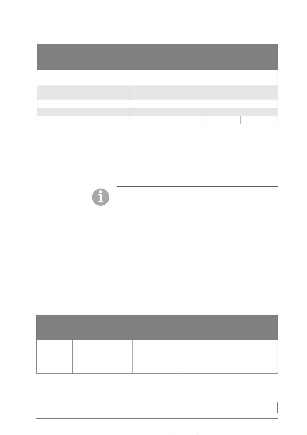
3.4 Fuel quality requirements
The heating systemHDG Compact 25 - 80 is designed for the
standard use of burning untreated wood in the form of wood chips,
pellets or shavings/pressed wood briquettes.
With regard to the quality standards for solid fuel, DIN EN ISO 17225
“Biogenic solid fuel - fuel specifications and classes - classification of
wood chips” applies.
• Part 4: “Classification of wood chips”
• Part 2: “Classification of pellets”
• Part 3: “Classification of wood briquettes”
In accordance with this standard, the properties of fuels that can be
usedHDG Compact 25 - 80 are specified below in detail.
WOOD CHIPS
Essential criteria for the definition of the property classes are particle
size, moisture content and ash content of the fuel.
ARTICLE SIZE In accordance with DIN EN ISO 17225-4, the particle sizes for wood
P
chips are classified into P45S.
Main content
P class
(mass fraction min.
60%)
P45S 3.15 mm < P ≤ 45 mm ≤ 10 % ≤ 10 % > 63 mm, all ≤ 85 mm
Fine content
(% by weight)
≤ 3.15 mm
Coarse content
(% by weight)
Max. length, max. cross section
(HDG Compact 25/35) and ≤ 120 mm
(HDG Compact 45/50/65/80), cross sec-
tion of the outsized particles ≤ 6 cm
2
Table 3/3 - Particle sizes for HDG wood chip boilers
25
Page 26

3 Mode of operation – Fuel quality requirements
Medium wood chips with a particle size of up to 45 mm (P45S) are
used in larger systems, but may however also still be suitable for
small systems depending on the diameter of the conveyor auger.
Oversized pieces (end pieces) could lead to malfunctions during
system operation. Higher proportions of finer content (dust) can lead
to high emissions and ejection of glowing particles.
Wood chips from category P45S HDG Compact 25 - 80 - as described
above - can be used as fuel in all HDG wood chip boilers. For the HDG
Compact 25/35, the maximum length of oversized particles is limited
to 85 mm and 120 mm for the HDG Compact 45/50/65/80.
W
ATER CONTENT When selecting fuel, note that the calorific value of the wood is pri-
marily dependent on the water content. The more water contained
in the wood, the smaller the calorific value, since the water vaporises
in the course of the burning process and thereby consumes heat.
This results in lower efficiency and thereby leads to greater wood
consumption. Increasing moisture in the fuel material also causes reduced efficiency of the boiler, greater amounts of ash and smoke, as
well as making it increasingly unfit for storage.
The maximum permissible water content of the wood chips is 20 %
(M20) for the HDG Compact 25/35 and 25 % (M25) for the HDG Compact 45/50/65/80 and complies with the property class A1. The water
content of the wood chips may not be under 10 % (M10) as a higher
aerosol formation causes a higher level of dust.
For technical considerations, a representative calorific value is selected depending on water content. For burning that is both economical and low on emissions, the calorific value should not be less
than 4 kWh/kg.
Water content Moisture Calorific value
Relative wood
consumption
10.0 % 11.1 % 4.6 kWh/kg 87 %
20.0 % 25.0 % 4.0 kWh/kg 100 %
26.0 % 35.0 % 3.7 kWh/kg 110 %
30.0 % 42.9 % 3.4 kWh/kg 120 %
Table 3/4 - Calorific value depending on water content
A
SH CONTENT For environmentally-friendly operation of the wood chip boiler, a low
ash content is required. At the same time, this also minimizes the
content of elements critical for combustion. Inorganic substances
which are aerosol forming, such as potassium, chlorine or sodium are
the main factors determining dust emissions in combustion. These
elements are predominantly found in the needles, leaves and bark of
the tree. Well-prepared, pure wood types, such as delimbed energy
wood without needles, leaves and only a minimal proportion of bark,
have the lowest content of elements critical for combustion. They are
therefore recommended for use in residential boiler systems.
26
The ideal ash content is a maximum of 1.0% by weight (A1.0) and this
complies with property class A1. When using wood chips with a
higher ash content (property class A2 and B1/2) secondary measures
Page 27

3 Mode of operation – Fuel quality requirements
(filter technology) may be necessary for complying with the dust
emission values according to the 1st Federal Emission Control Ordinance (2nd stage).
WOOD PELLETS
Wood pellets are pressed into a cylindrical shape. They consist of untreated shavings and sawdust from the wood processing industry as
well as unprocessed forestry waste. They have a standardised diameter and length. They are pressed at a very high pressure and have a
very low water content. The energy contained in 2 kg of pellets corresponds approximately to the energy contained in a litre of heating
oil.
Essential criteria for the definition of the property classes are the
length and diameter, moisture content and ash content of the fuel.
L
ENGTH AND DIAMETER The diameter of the pellets used must be in accordance with the op-
eration of the HDG Compact 25 - 80 connected TBZ 90 with pellet
suction system D06. When connected to another delivery system
(e.g. HDG flexi blade delivery system, HDG hinged arm delivery
system or HDG pellet delivery system PSZ), the diameter can also
comply with D08.
• D06
The diameter of the pellets must be 6 mm +/- 1 mm. The length of
the pellets must measure between 3.15 mm and 40 mm. A maximum
of 1.0% by weight of the pellets may be longer than 45 mm.
• D08
The diameter of the pellets must be 8 mm +/- 1 mm. The length of
the pellets must measure between 3.15 mm and 40 mm. A maximum
of 1.0% by weight of the pellets may be longer than 45 mm.
W
ATER CONTENT The water content must be less than 10% (M10) for property classes
A1, A2 and B.
A
SH CONTENT The ash content of the property class A2 and B is higher than that of
A1 due to the higher proportion of bark, needles and leaves. The
maximum ash content for property class A1 is 0.7% by weight (A0.7),
for property class A2 the maximum ash content is 1.2 % by weight
(A1.2) and for property class B the maximum ash content is 2.0 % by
weight (A2.0). In accordance with the 1st Federal Emission Control
Ordinance, operation with pellets in Germany is limited to property
class A1.
Alternatively pellets with the “ENplus” or “DINplus”, certificate are
also suitable as these also meet the quality requirements of property
class A1.
27
Page 28
3 Mode of operation – Fuel quality requirements
PRESSED WOOD BRIQUETTES
For the HDG Compact 45/50/65/80, pressed wood briquettes can
also be used as fuel. Pressed wood briquettes are pressed shavings,
with or without various forms of additives, with a diameter of more
than 25 mm.
Essential criteria for the definition of the property classes are the
length and diameter, moisture content and ash content of the fuel.
L
ENGTH AND DIAMETER • D60/L50
The diameter of the pressed wood briquettes must not exceed
60 mm and the length must not exceed 50 mm.
W
ATER CONTENT The water content must not exceed a maximum of 12 % (M12) for
property class A1 and a maximum of 15 % (M15) for property class A2
and B.
A
SH CONTENT The ideal ash content is a maximum of 1.0% by weight (A1.0) and this
complies with property class A1. When using pressed wood briquettes with a higher ash content (property class A2 and B) secondary measures (filter technology) may be necessary for complying
with the dust emission values according to the 1st Federal Emission
Control Ordinance (2nd stage).
RECOMMENDED FUEL
It is important that fuel is used according to HGD fuel specifications
in order to be able to guarantee compliance with emission limit
values under the 1st Federal Emission Control Ordinance (2nd stage).
In particular, all fuel requirements concerning size, water content
and ash content must be met. Without the use of secondary measures (filter technology), only fuels of property class A1 are suitable for
this in each case.
Pay particular attention to the fuel quality, both when ordering and
at delivery.
Important!
If there is a significant change of fuel, the system must be reset accordingly and checked for emissions by authorised specialists.
PERMITTED FUEL IN ACCORDANCE WITH 1ST FEDERAL EMISSION CONTROL ORDINANCE (GERMANY)
28
Additional quality requirements apply in Germany independently of
the fuel specification in accordance with DIN EN ISO 17225. In accordance with Section 3 (1) of the 1st Federal Emission Control Ordinance,
Page 29
3 Mode of operation – Fuel quality requirements
the fuel classes 4 (wood chips), 5 (shavings), 5a (pellet) may be used
in the HDG Compact 25 - 80 heating system and also for fuel classes
6 and 7 for the HDG Compact 45/50/65/80.
F
UEL CLASS 6 Painted, varnished or coated wood including remains thereof, pro-
vided no wood protection agents have been applied or are present
as the result of a treatment, and coatings do not contain organic halogen compounds or contain heavy metals.
F
UEL CLASS 7 Plywood, chipboard, fibreboard or otherwise glued wood including
remains thereof, provided no wood protection agents have been applied or are present as the result of a treatment, and coatings do not
contain organic halogen compounds or heavy metals.
Fuel classes 6 or 7 may only be used in a wood processing plant at 30
kW or more nominal thermal power. In the case of painted, varnished
or coated wood, it should be noted that greater stress can be placed
on the wearing parts such as combustion chamber, fill level and
lambda sensors, which may reduce their service lives.
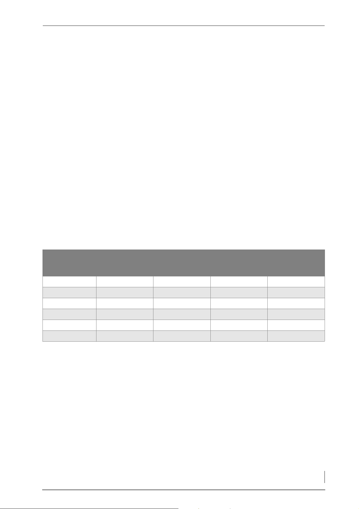
NOMINAL THERMAL VALUE DEPENDING ON WATER CONTENT
The following table indicates the maximum nominal thermal power
depending on water content, in reference to the fuels approved for
the HDG Compact 25 - 80 in accordance with DIN EN ISO 17225 “Biogenic solid fuel - fuel specifications and classes”.
A1 P31S, M20, A1.0
wood chips and A1
pellets
A1 P45S, M25, A1.0
wood chips
A1 D60, L50, M12,
A1.0 pressed wood
briquettes
A1 shavings
M20, A1.0
HDG Compact 25 31 kW and 26 kW 28 kW - HDG Compact 35 31 kW and 35 kW 28 kW - HDG Compact 45 45 kW 43 kW, (42 kW) 43 kW 42 kW, (40 kW)
HDG Compact 50 50 kW 48 kW 48 kW 47 kW
HDG Compact 65 65 kW 63 kW 63 kW 62 kW
HDG Compact 80 80 kW and 85 kW 78 kW 78 kW 77 kW
Table 3/5 - Max. nominal thermal power depending on water content
29
Page 30
4 Planning and installation – Dimensions
4 Planning and installation
B
E
A
D
C
F
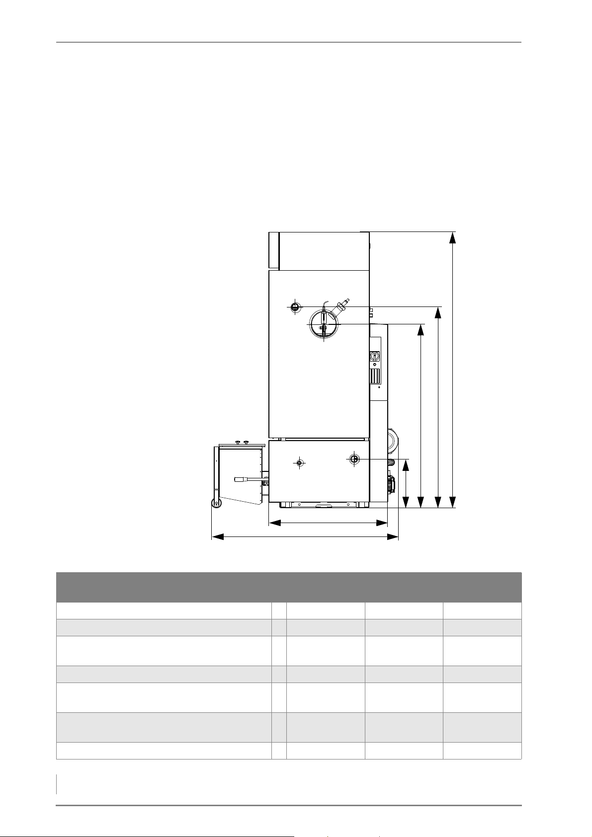
4.1 Dimensions
FLUE GAS PIPE SIDE HDG COMPACT 25 - 80
Boiler height A 1655 1920 1920
Flow connection height B 1175 (DN32 IG) 1400 (DN32 IG) DN40 IG
Height at middle of the flue gas pipe
connection
Return connection height D 340 (DN32 IG) 340 (DN32 IG) 340 (DN40IG)
Depth of boiler without attachments and
ash removal
Depth of boiler with attachments and
ash removal
Diameter of flue pipe connection 150 180 200
30
Figure 4/1 - Dimensions of flue gas pipe side HDG Compact 25 - 80
HDG Compact
25/35
C 820 1280 1280
E 700 830 830
F 1100 1300 1300
Table 4/1 - Dimensions of flue gas pipe side HDG Compact 25 - 80 (mm)
HDG Compact
45/50/65
HDG Compact
80
Page 31
4 Planning and installation – Dimensions
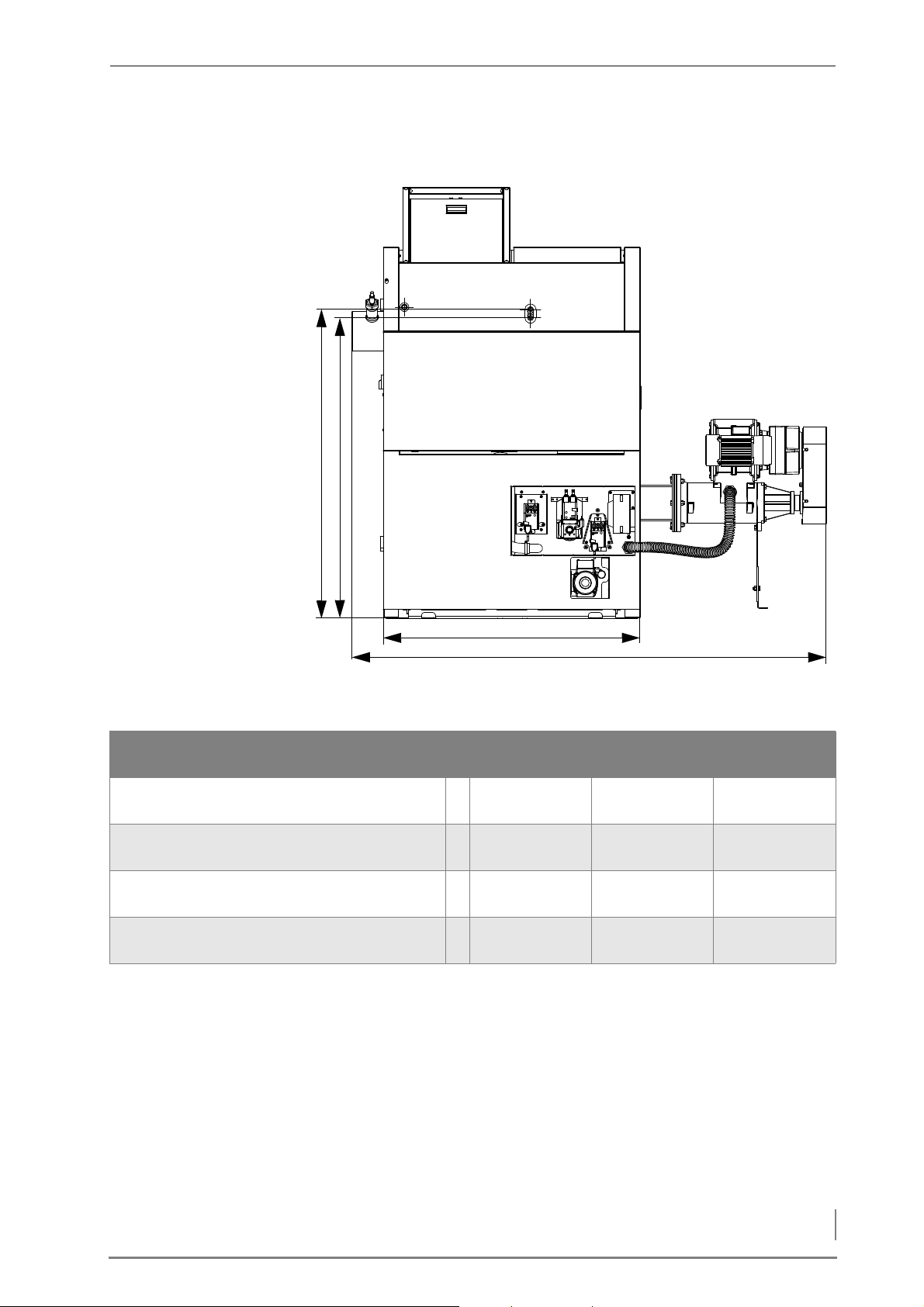
HDG COMPACT 25 - 80 BACK SIDE
B
A
D
C
Figure 4/2 - HDG Compact 25 - 80 back side
HDG Compact
Height of input for safety heat exchanger A 1155
Height of output for safety heat exchanger B 1155
Width of boiler without attachments and flue
C 1150 1150 1450
gas pipe connection
Width of boiler with attachments and flue gas
D 2200 2110 2420
pipe connection
Table 4/2 - Dimensions on back side, HDG Compact 25 - 80 (mm)
25/35
(DN15 AG)
(DN15 AG)
HDG Compact
45/50/65
1380
(DN15 AG)
1340
(DN15 AG)
HDG Compact
80
1380
(DN15 AG)
1340
(DN15 AG)
31
Page 32
4 Planning and installation – Structural requirements
4.2 Structural requirements
C
F
B
D
A
E
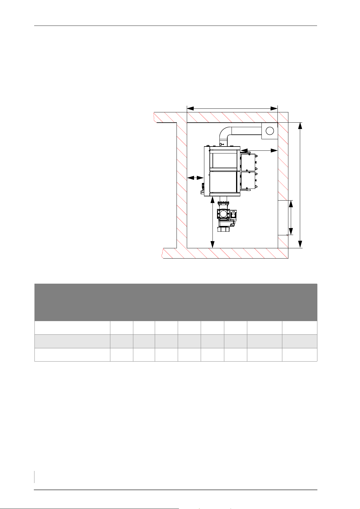
REQUIRED ROOM SIZES AND MINIMUM CLEARANCES
Figure 4/3 - Required room sizes and minimum clearances
Minimum
A B C D E F
HDG Compact 25/35 2900 700 1800 400 700 1200 1950 2250
HDG Compact 45/50/65 2900 800 2000 400 700 1200 2250 2500
HDG Compact 80 3150 800 2000 400 700 1200 2450 2750
Table 4/3 - Minimum size (mm)
room
height
Recom-
mended
room
height
BOILER INSTALLATION SITE/BOILER ROOM
BOILER INSTALLATION SITE Heating systems for solid fuels with a nominal thermal power of up to
50 kW may be installed in a boiler room.
B
OILER ROOM Boilers for solid fuels with a nominal thermal power of more than 50
PPLICABLE REGULATIONS Local building regulations always apply. In Germany, individual state
A
kW may only be installed in special boiler rooms.
regulations on boilers and furnaces (FeuVO) also apply.
32
Page 33

4 Planning and installation – Structural requirements
Building regulations may differ from country to country and state to
state.
For this reason, consult a qualified specialist for the planning and installation of your boiler room.
Make sure there is an adequate supply of fresh air to the boiler room
so that there is enough air available for the combustion process and
to protect the operator from the hazards of insufficient oxygen.
I
NSTALLATION A base is not necessary for installation of the boiler. Ensure that the
floor is level.
Observe the fire safety regulations.
For unhindered operation and maintenance of the heating system,
you must ensure that it is installed to our specifications and that the
minimum clearances are maintained.
Also note that the thresholds in DIN 4109 “Soundproofing in building
construction” may not be exceeded.
More detailed information can be found in the respective ordinances
of the German states.
Also observe the accident prevention regulations of the official
safety organisations.
We recommend that objects which are not needed for the operation
or maintenance of the heating system not be stored in the boiler
room.
FUEL STORAGE
The fuel storage should have the following characteristics:
• dry
• dust-proof
• structurally suitable
• accessible for the filling process
• free of other installations, especially in existing buildings
• adapted to fuel requirements
The refilling intervals should be kept as long as possible. The HDG
Compact 25 - 80 heating system should be located so that the noise
generated does not exceed the permitted values of DIN 4109
“Soundproofing in building construction”.
P
ROPER DIMENSIONING The size of the fuel storage depends on the heating system, the de-
termined heating demand, the resulting annual fuel requirements
and existing building conditions. Practice has shown that filling the
fuel storage four to six times per heating period is ideal.
ASSAGE THROUGH THE WALL The passage through the wall usually has to be made in the wall be-
P
tween the boiler installation site and the fuel storage. Its position depends on the distance and the position of the HDG Compact heating
33
Page 34

4 Planning and installation – Connections
system within the room and the customer's installation diagram. Due
to the auger assembly, the passage through the wall should have a
width of 70 cm as well as a height of 70 cm.
V
ENTILATION OF FUEL STORAGE Wood fuel products with higher moisture can cause relatively high
air humidity in the fuel storage. Cold surfaces may thereby experience a drop below the dew point and form condensation. This condensation water often occurs on non-insulated lids, doors or cold
walls and can result in a further moistening of the fuel. It is therefore
recommended to provide a suitable ventilation system that corresponds to the building's features.
4.3 Connections
CHIMNEY
According to EN 303-5, the entire flue system must be installed in
such a way that contamination, condensation and insufficient flue
draught are avoided. Here it is to be noted that, in the accessible operational area of the boiler, flue gas temperatures of less than 160 K
above room temperature may arise.
✎ The required flue gas values are listed in chapter “3 Mode of op-
eration”, section “3.3 Technical data”.
The benefits of the HDG Compact 25 - 80 can only be reaped if all of
the factors necessary for good combustion are carefully adjusted.
The heating system and chimney form a single functional unit and
must be adapted to one another in order to guarantee fault-free and
economical operation.
Since the flue gas temperature may lie below 100°C when the system
is under partial load, a chimney/flue is required which meets the requirements of DIN EN 13384-1: 2003-03 “Thermal and fluid dynamic
calculation methods”. If it does not meet this standard, contact your
specialist heating company or chimney engineer.
When planning the flue system, a flue calculation based on DIN EN
13384-1 must be performed by authorised specialists.
Another essential criterion is meeting the flue draught requirement.
This depends on three major factors.
C
HIMNEY CHARACTERISTICS The requirements for minimising the draught loss in the chimney are:
• Good thermal insulation to avoid the flue gases cooling down too
quickly.
34
• Smooth interior surface to reduce the flow resistance.
• Chimney well-sealed to avoid outside air leaking in. Air pene-
trating from the outside speeds up the cooling of the flue gases.
These requirements correspond to chimneys of the type conforming
to DIN EN 13384-1: 2003-03 “Thermal and fluid dynamic calculation
methods”.
Page 35

4 Planning and installation – Connections
Free-standing chimneys require particularly good insulation.
2
A
B
1
C
HIMNEY DIMENSIONS The system may only be connected to a chimney which has been di-
mensioned in accordance with DIN EN 13384-1, taking into account
the fuel planned and the expected load, and which meets local
building regulations for the installation site.
A chimney can only be designed with full knowledge of the on-site
conditions. This includes taking into account the following factors:
• Building location
– Surrounding hills/slopes
– Wind direction
• Location of the chimney in the roof
– The opening of the chimney must be at least 0.5m above the
highest edge of roofs with a slope of more than 20° or at least
1.0 m higher than roof surfaces which slope at 20° or less.
• The effective height of a chimney is measured from the flue en-
trance into it to the end of the chimney.
C
ONNECTING THE BOILER TO
THE CHIMNEY
The firing system must be connected with a connecting piece which
is as short as possible, at an angle which is less than 30 - 45° to the
chimney.
You should aim for a connecting piece with a maximum length of 1
m using just one fitting. Every additional fitting results in a greater
pressure loss in the exhaust path and should thus be avoided. The
same is true for overly long connecting pieces. If, for constructional
reasons, these must be longer than 1 m, they should be adequately
insulated (at least 5 cm of mineral wool or equivalent material) and, if
possible, fitted with an upward inclination.
1 Auxiliary air unit
2Cleaning door
A) Chimney approx. 30° - 45°
B) Clearance at least 50 cm
Figure 4/4 - Connection to the chimney
To compensate for irregularities in the flue draught of the chimney,
HDG Bavaria recommends installing an auxiliary air unit in the flue
gas pipe, or even better, in the chimney itself as shown in Figure 4/4
- Connection to the chimney.
35
Page 36
4 Planning and installation – Connections
The following should also be considered:
• The connecting piece may not protrude into the chimney.
• If the system flue gas pipe has a larger diameter than the chimney,
the connecting piece must reduce its diameter to that of the connection. In this case, the cone of the connecting piece should
taper as narrowly as possible.
• Use bends rather than elbows; the radius of the elbow may not be
less than the diameter of the pipe.
• The chimney should be vertical and straight, if possible without
deformations (take particular care in older buildings).
• All of the cleaning doors and measurement hatches on the
chimney must have tight seals.
• To reduce the entry of additional cold air, only one heat source
should be attached to each chimney.
• To prevent dust from escaping, the flue gas pipe must be sealed
with heat-resistant silicone.
ELECTRICAL SYSTEM
L
IGHTNING/SURGE PROTECTION
The directives of 2006/95/EC (low voltage guidelines) must be followed for the electrical connections to the system.
No electrical installations, such as power sockets, distribution boxes,
lights or light switches may be located in the fuel storage. Any lights
must be suitable for use in areas at risk of explosion. The VDE regulations for rooms with a risk of dust explosion must be followed.
✎ The required connection values are described in chapter “3 Mode
of operation”, section “3.3 Technical data”.
Important!
To operate the heating system safely and properly we recommend
protecting the electronic components with a lightning and surge
protection according to DIN EN 62305 or DIN VDE 0100-443. Please
contact your specialist electrical service.
WATER
Important!
36
The heating system must be filled with water in accordance with
VDI guideline 2035, “Avoiding damage in hot water heating systems”.
The coatings formed by stones in the heat generator can have a detrimental effect on the efficiency (energy efficiency) of the heating/
boiler system and can lead to damage and faults.
Page 37

4 Planning and installation – Connections
Antifreeze agents may only be used after prior consultation with
HDG.
USING AN ACCUMULATOR When calculating the thermal requirements of buildings, e.g. ac-
cording to DIN EN 12831 “Method for calculating the normal heating
load”, the lowest outside temperature of the relevant climate zone
(e.g. -15 °C) is used. These conditions only apply a few days per year,
thus, the thermal performance of the heating system is greater than
required on most days when heating is needed. For this reason, the
HDG Compact 25 - 80 is fitted as standard with power control and automatic ignition.
It is, however, highly recommended to use an accumulator even
with automatic boiler systems.
The size of the accumulator will depend on the nominal thermal
power of the boiler and on the thermal requirements of the building.
As a benchmark value, 20 litres per kilowatt boiler power can be
used. This results in a boiler burning duration of approximately one
hour at full-capacity operation, during which the accumulator is
completely filled. The emptying time of the accumulator at 25 %
nominal load is 3.7 hours for this type of design, with an assumed usable temperature difference of 40 Kelvin.
An advantage of using an accumulator lies in the lower operating
hours of the system and fewer start-up phases due to the extension
of the heating intervals. This leads to a reduction in the proportion of
external energy supplied and to lower wear of the mechanical components.
One further advantage of the accumulator is in summer operation
when only hot water is required. When operating in this mode, the
accumulator helps avoid frequent ON/OFF switching.
For the above-mentioned reasons we recommend an accumulator, even for automatic boiler systems.
S
AFETY DEVICES Safety devices (e.g. boiler safety module, insufficient water cutout,
etc.) must be installed in accordance with DIN EN 12828: 2003 “Design of water-based heating systems in buildings”.
CTIVATE RETURN
A
TEMPERATURE
Operating temperatures which are too low significantly shorten the
service life of the boiler. Water vapour contained in the flue gas could
be released in the form of condensation if the temperature drops
below the dew point (approx. 50–55 °C), especially in the area around
the water-cooled heat-exchanger surfaces. This condensation, in
combination with combustion residue, can lead to corrosion.
For these reasons, a return temperature control must be installed for
the HDG Compact 25 - 80 heating system. The return temperature
control causes the water from the boiler return flow to be mixed with
the water from the boiler supply flow until the minimum return temperature has been reached.
✎ The minimum return temperature is listed in chapter “3 Mode of
operation”, section “3.3 Technical data”.
The control of the return temperature is handled by the HDG Control
control unit.
37
Page 38
4 Planning and installation – Scope of delivery
The return temperature control consists of a 3-way mixing valve with
a 230 V servo drive (running time 120-240 s) and a circulation pump
from energy efficiency class A. We recommend for the
• HDG Compact 25/35/45/50/65:
Wilo 30/1-7.5, 3-way mixing valve DN 32
• HDG Compact 80:
Wilo 30/1-8, 3-way mixing valve DN 40
(or comparable)
The pipe dimensions must be adapted to meet the requirements at
the site. Take the water-side connections of the boiler for the supply
and return into account.
✎ See chapter “3 Mode of operation”, section “3.3 Technical data”.
The hydraulic system must be installed in accordance with specific
technical principles of the heating construction industry. Take into
account the isolation valves required for maintenance work and repairs.
The return temperature control is not designed for the use of a
gravity brake and this should therefore not be installed.
The return temperature control must be installed according to the
specifications of HDG Bavaria.
4.4 Scope of delivery
Included in the scope of delivery:
• HDG Compact 25 - 80 boiler
• Cladding
Packet Change
1A Supporting structure and assembly
material
1B Back side in packet 1A x x
2 Feeding system side and flue gas pipe
side
3 Cladding for pellet vacuum container o o o
4 Front and top x x x
Table 4/4 - Dimensions on back side, HDG Compact 25 - 80 (mm)
x = included, o = optional
HDG Compact
25/35
xxx
xxx
HDG Compact
45/50/65
HDG Compact
80
38
• Feeding system (customer-specific)
• Delivery system (customer-specific)
• Cleaning tools
• Operating documentation
Upon delivery, check that the scope of delivery matches the information on the delivery note.
Page 39
4 Planning and installation – Installing the heating system
4.5 Installing the heating system
The heating system will be commissioned by specialists from HDG
Bavaria or from an authorised HDG partner and a qualified electrician.
Danger!
Risk of material damage and injury due to incorrect installation
Installing the system requires comprehensive specialist knowledge.
If installed by untrained persons, the heating system can be damaged and persons may be injured due to secondary damages.
Only allow authorised specialists to perform the installation.
Danger!
Dangerous electrical current or voltage
Working on live components can result in an electric shock.
Switch off the mains supply to the heating system during the instal-
lation.
Important!
When laying the pipelines, observe the minimum required clearances.
✎ See section “4.1 Dimensions” in this chapter.
Important!
Due to the noise, we recommend acoustic insulation measures for
components which are in contact with the floor, wall or ceiling of
the heating room.
The following figures and diagrams show the version of the heating
system HDG Compact 25 - 80 with feeding system TBZ 150 on the
left side of the boiler.
Please keep this in mind if your version has a feeding system on the
right.
39
Page 40
4 Planning and installation – Installing the heating system
INSTALLING THE BOILER
2
1
Caution!
Danger from suspended loads
The boiler weighs over 600 kg. If the boiler is dropped during trans-
port, persons can be seriously injured and the boiler can be damaged.
Make sure that you use appropriate lifting gear when placing the
boiler.
1. Remove the packaging from the boiler.
The boiler packaging can be taken to the local recycling company.
Important!
When using the installation aid, observe the required minimum
clearance of 60 cm to the side walls in order to be able to later remove the aid.
Also observe the minimum clearance of 150 cm in front of and behind the boiler so that you can remove the pallet.
RANSPORTING WITH A PALLET
T
TRUCK
The final installation position of the boiler must be adjusted afterwards if necessary.
2. Transport the boiler to its installation site.
3. Set down the boiler with the pallet at the planned location while
observing the minimum clearances.
✎ See “4.1 Dimensions”, section “Required room sizes and minimum
clearances” in this chapter.
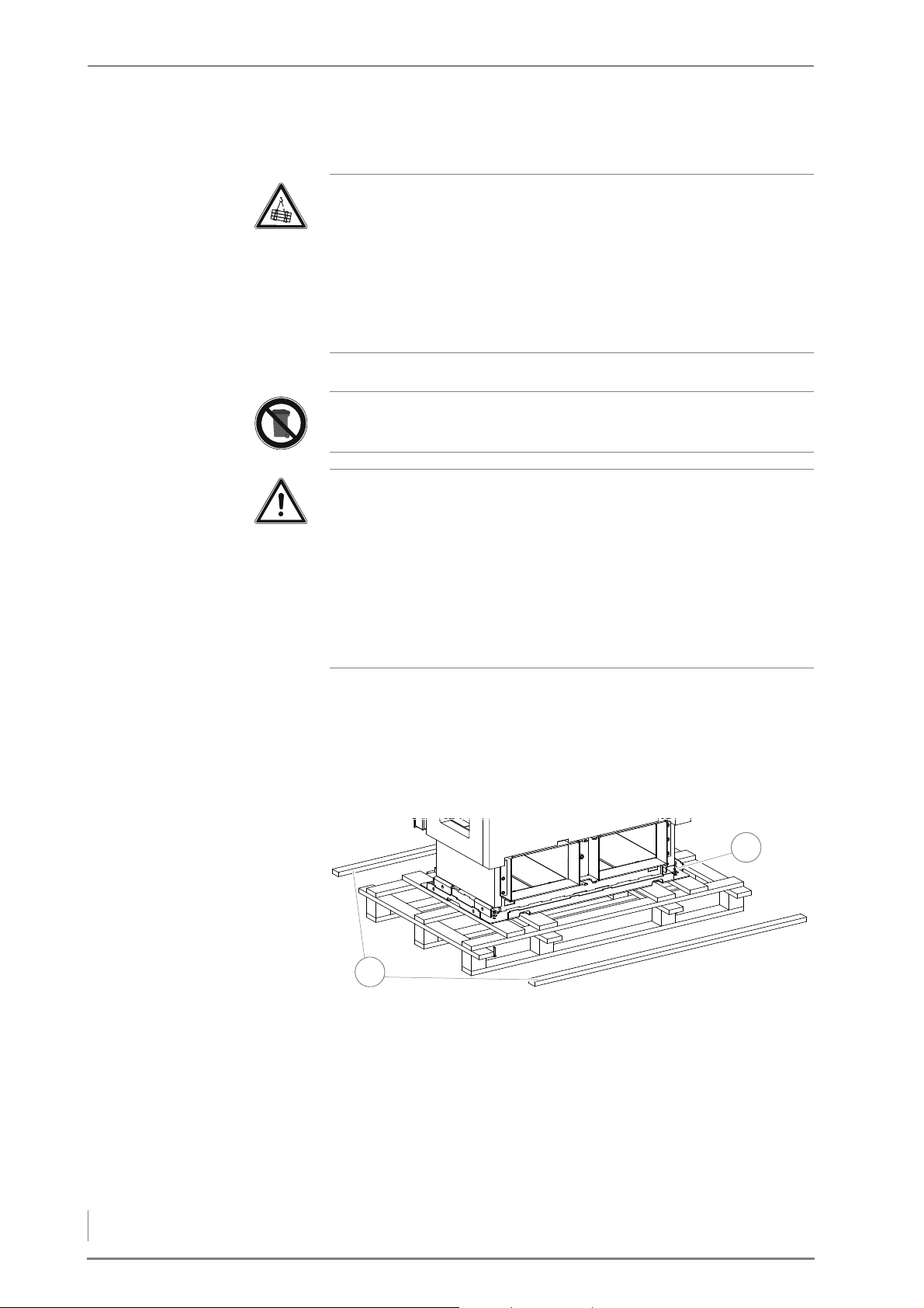
Figure 4/5 - Undo the pallet attachments
4. Remove the two side slats (1) from the pallet.
40
Page 41
4 Planning and installation – Installing the heating system
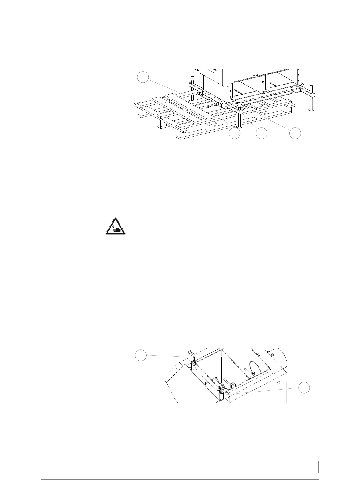
5. Undo the M8 (size 13) (2) nuts in the four corners of the boiler and
4
1
32
2
1
press the M8 screws downwards.
Figure 4/6 - Installation aid
6. Push each of the square shafts (3) into the guides intended for
them.
7. Secure the square shaft (3) with the M12 screw (2).
8. Turn each of the spindles (4) (size 24) until the boiler is completely
supported on the installation aid.
9. Remove the pallet (1).
Warning!
T
RANSPORT WITH A CRANE
Danger of injury
If you screw a spindle on a corner down completely, there is the risk
that the boiler will tip over. This could cause serious injuries as well
as damage to the boiler.
Turn each of the spindles in alternating brief turns.
10.Screw down the spindles (size 24) on the four corners in alter-
nating brief turns until the boiler rests completely on the floor.
11.Align the boiler with plastic plates or flat steel strips (not included
in the scope of delivery) so that it is level.
12.Remove the installation aid.
✓ The boiler is erected.
Figure 4/7 - Crane eyelets
1. Fasten the crane hooks on the crane eyelets (3) according to the
instructions on the sticker.
2. Carefully lift the boiler.
3. Remove the pallet from the boiler.
41
Page 42
4 Planning and installation – Installing the heating system
4. Transport the boiler to its installation site.
Z
u
A
u
f
2
1
3
5. Place the boiler at the planned location while observing the min-
imum clearances.
✎ See “4.1 Dimensions”, section “Required room sizes and minimum
clearances” in this chapter.
6. Align the boiler with plastic plates or flat steel strips (not included
in the scope of delivery) so that it is level.
✓ The boiler is erected.
INSTALLING THE COMBUSTION FAN
The combustion air fan is only available with the
HDG Compact 45/50/65/80 boiler.
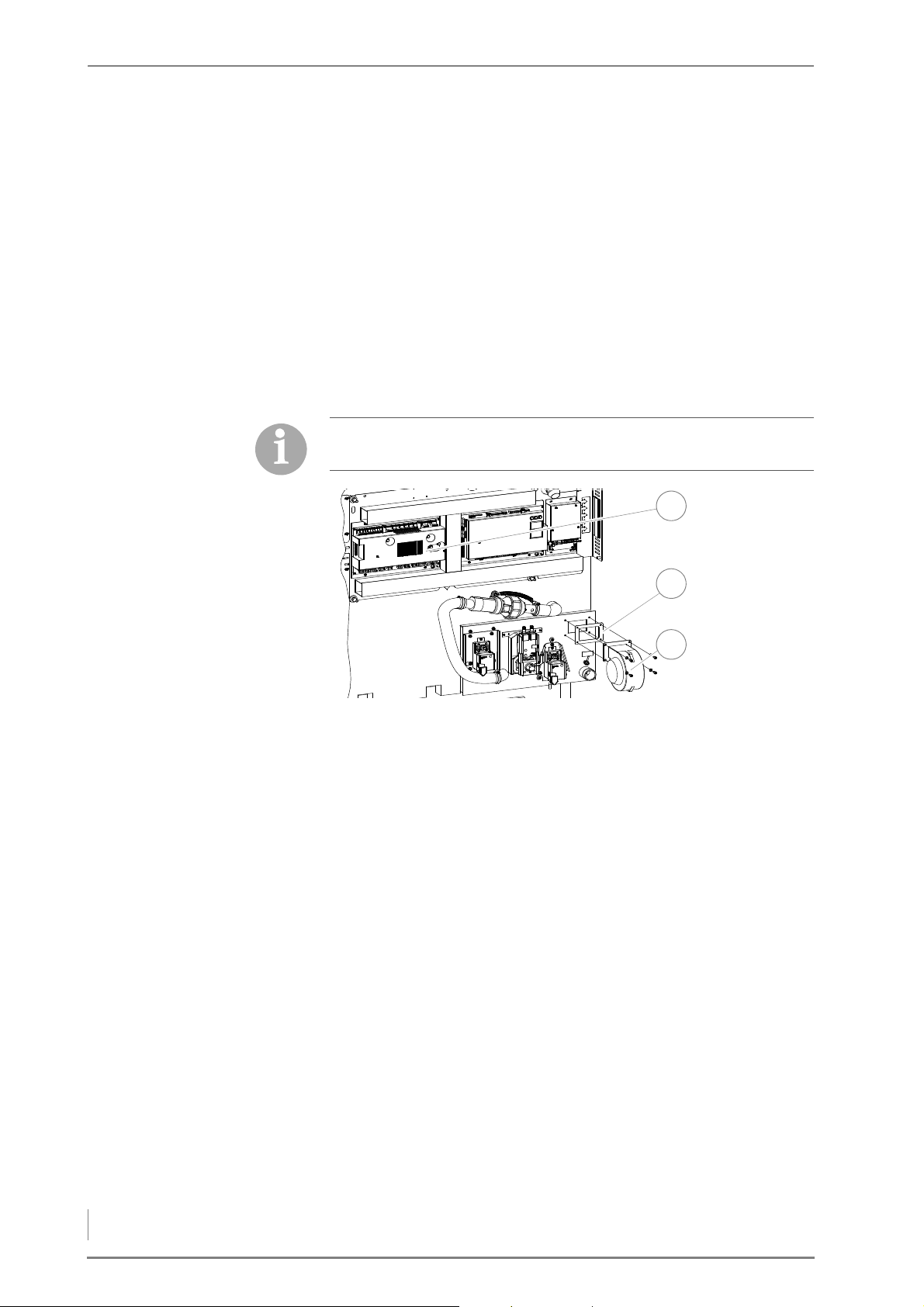
Figure 4/8 - Installing the combustion fan
1. Release the four 5 mm M6 hexagon socket screws (3) of the intake
for the combustion fan on the air control unit.
2. Fasten the combustion air fan (3) (with a seal (2) placed in be-
tween) to the air control unit using the four (5 mm) M6 hexagon
socket screws.
3. Connect the cable of the combustion air fan to the central module
(1) as illustrated in the circuit diagram.
✓ The combustion fan is installed.
42
Page 43
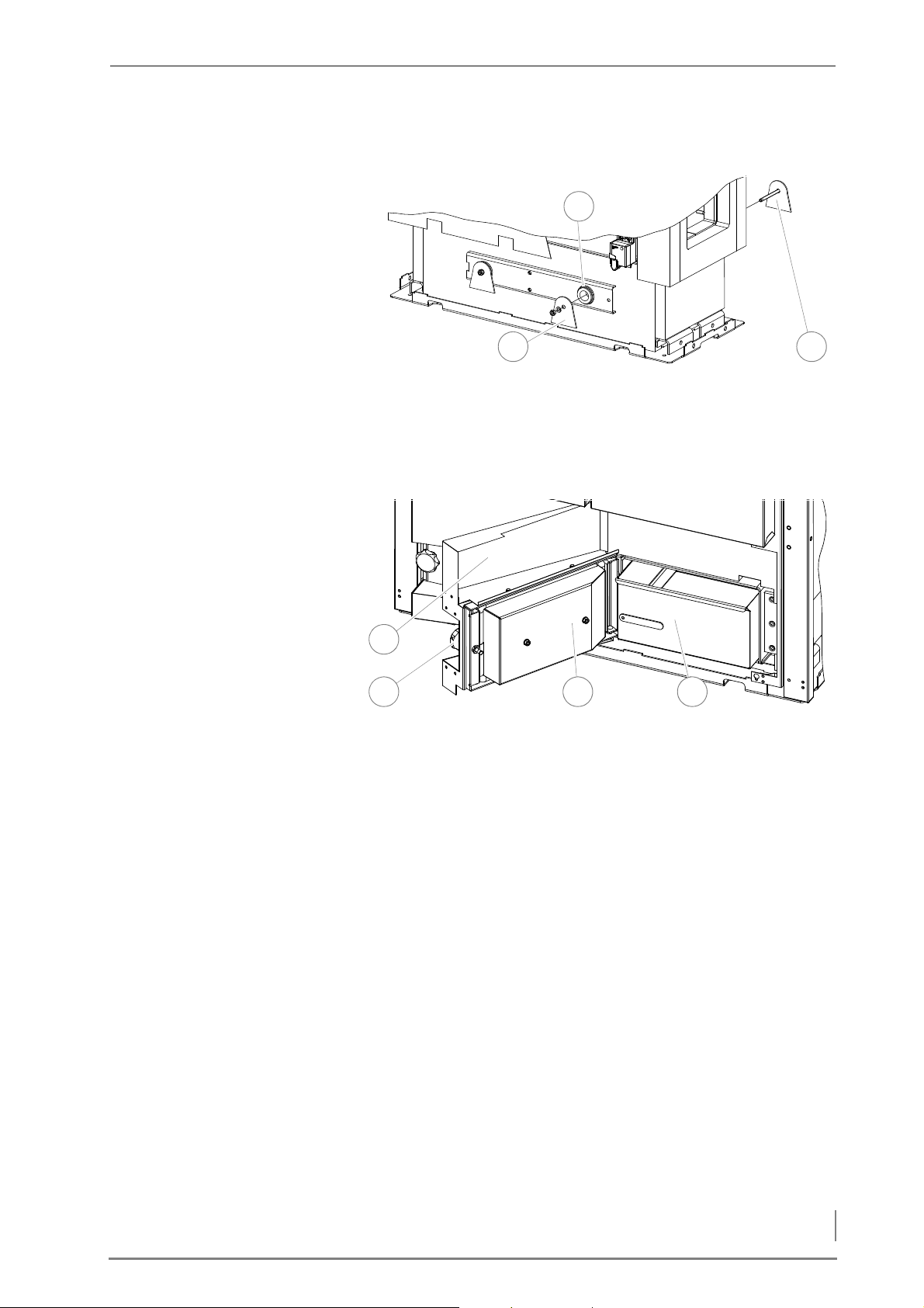
4 Planning and installation – Installing the heating system
INSTALLING THE MANUAL ASH REMOVAL
1 3
2
1
432
Figure 4/9 - Installing the sealing plates
1. Guide the sealing plate with the welded screw (3) through the
opening (2) for the ash removal auger.
2. On the opposite side, install the sealing plate (1) with the M10 (size
17) nut and M10 spring ring to the welded screw.
Figure 4/10 - Installing the door cladding
3. Hang each ash door (3) with the semi-circular rivets into the
hinges.
4. Assemble the door cladding (1) with the M5 (size 8) screws and M5
washer onto the ash door (3).
5. Place the ash pan (4) in the ash compartment.
6. Seal each ash door (3) using the star grip screw (2).
✓ The manual ash removal is installed.
43
Page 44
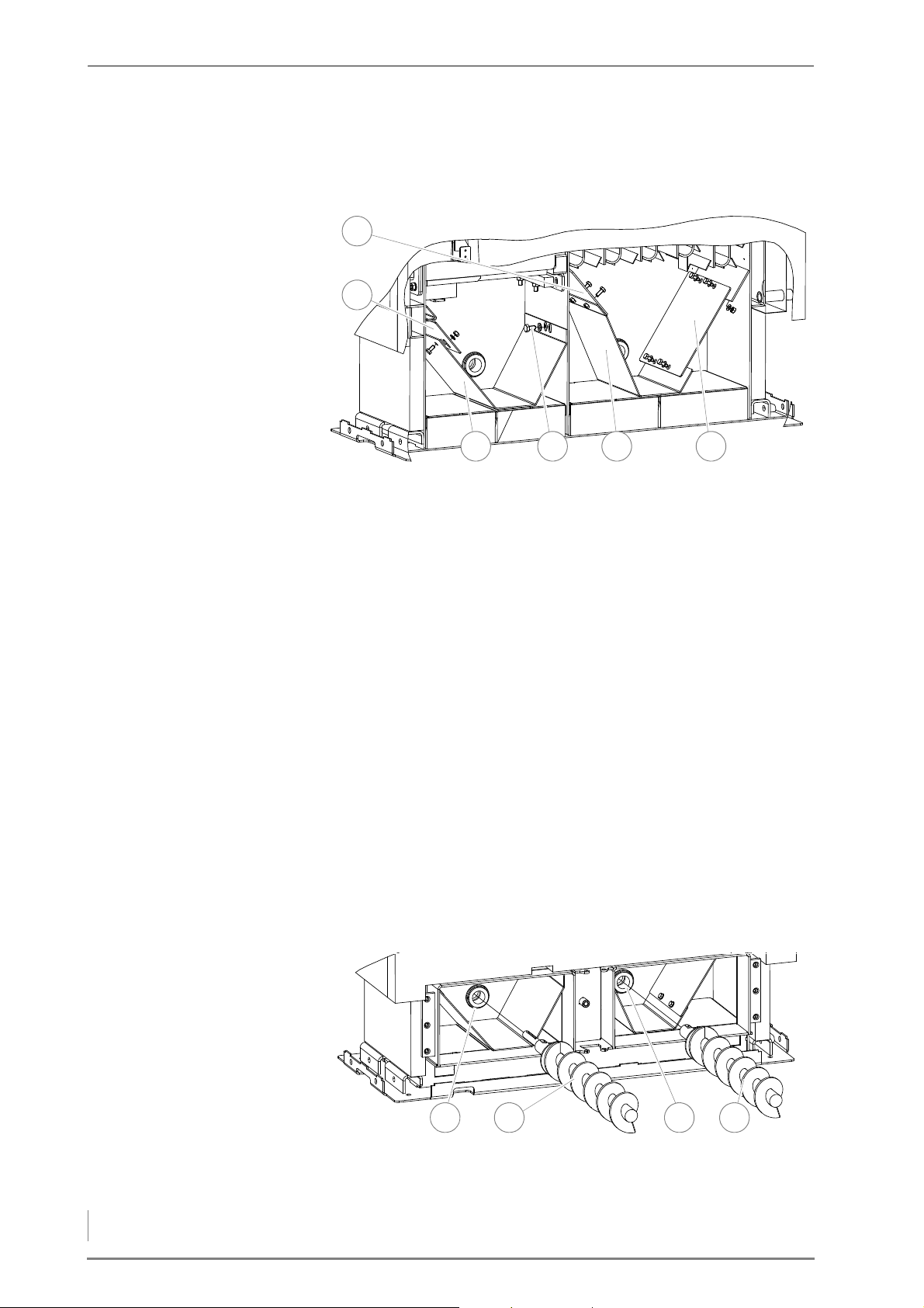
4 Planning and installation – Installing the heating system
INSTALLING THE ASH PLATES
1
6543
2
1 32 4
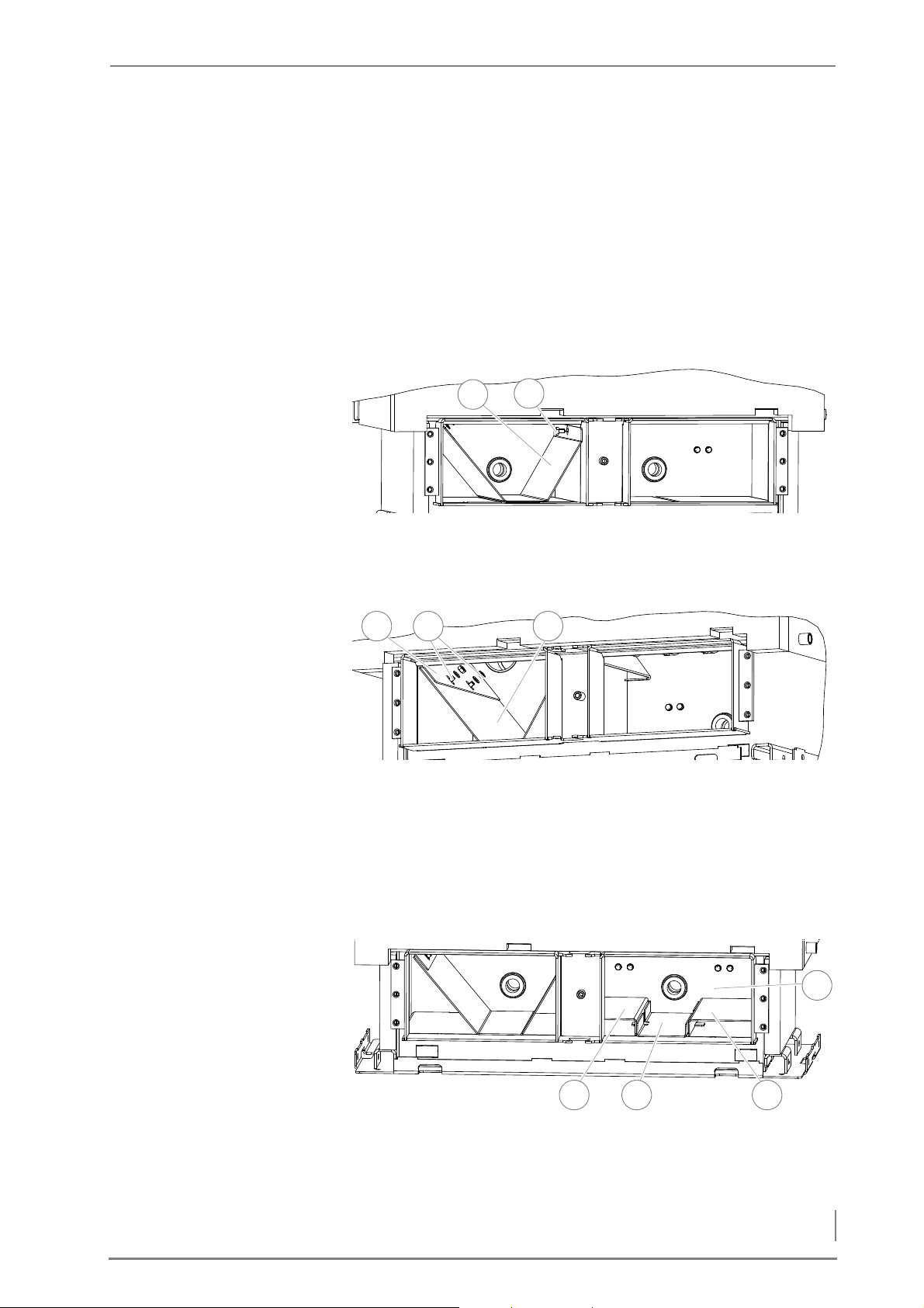
INSTALLING THE AUTOMATIC ASH REMOVAL SYSTEM HDG COMPACT 25/35
Figure 4/11 - Installing the ash plates
1. Slide the ash plate (3) from the front on the feed side into the ash
compartment of the combustion chamber.
2. Tighten the ash plate (3) with the M10 screw (size 17) (4) and M10
washer.
I
NSTALLING THE ASH REMOVAL
AUGER
3. Mount the alignment plate (2) on the ash plate (3) with the two M8
screws (size 13), but without tightening the screws.
4. Slide the alignment plate (2) all the way to the limit of the ash
compartment wall.
5. Remove the four M8 screws (size 13).
6. Slide the second ash plate (5) from the front into the fly ash com-
partment.
7. Install the adjustment plate (6) with the M8 screws and nuts (size
13) and M8 washer on the ash plate (5) and sloping plate of the ash
compartment.
8. Tighten the adjustment plate (6) with the M8 screws and nuts (size
13) and M8 washer on the ash plate (1) and sloping plate of the ash
compartment.
Figure 4/12 - Installing the ash removal augers
9. Insert the ash removal auger with the long shaft end (2) from the
44
front on the feed side through the opening (1) provided for this.
Page 45
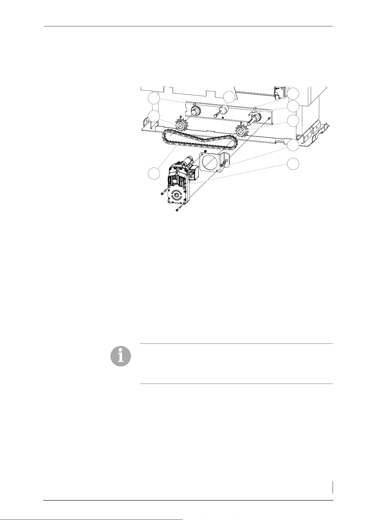
4 Planning and installation – Installing the heating system
M
1
9
2
3
6
7
8
5
4
OUNTING THE ASH REMOVAL
MOTOR
10.Insert the second ash removal auger with the short shaft end (4)
from the front through the opening (3) provided for this.
Figure 4/13 - Mounting the ash removal motor
11.Place the two feather keys (2 + 4) in the recesses provided for
them on the auger shafts.
12.Align the sprockets (1 + 6) flush on the auger shafts and fasten
them with the two hexagon socket screws.
13.Place the feather key (4) in the recess provided on the feed side
auger shaft.
14.Mount the drive chain (9) on the two sprockets (1 + 6).
15.Fasten the ash removal motor (8) with the M8 hexagon socket
screws (6 mm) on the torque support (7).
16.Insert the ash removal motor (7) with the torque support (6) on the
feed side auger shaft and fasten the support plate onto the boiler
with the M10 screw and nut (size 17).
For the version of the boiler with the feeding system on the left side,
the chain tensioner must be fastened in the upper position.
For the version of the boiler with the feeding system on the right
side, the chain tensioner must be fastened in the lower position.
17.Mount the chain tensioner (3) on the boiler with the M10 screw
(size 17).
45
Page 46
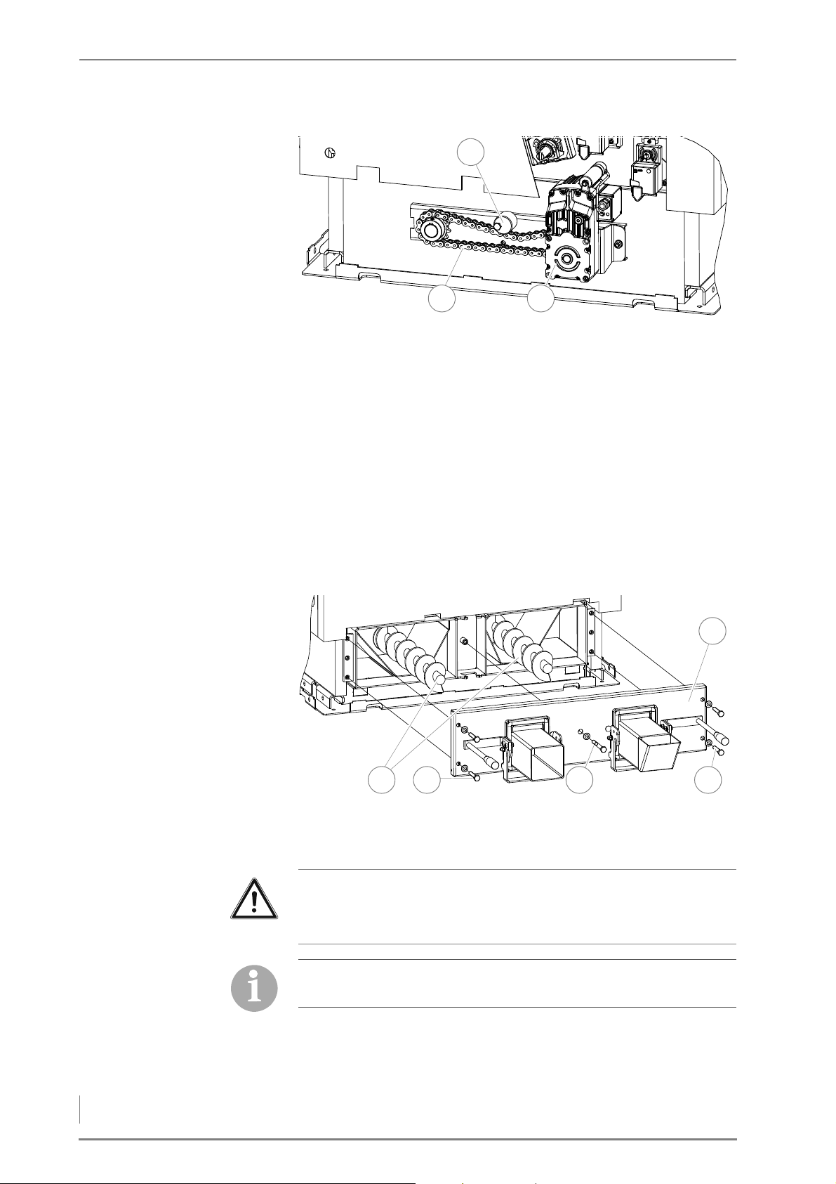
4 Planning and installation – Installing the heating system
C
1
2 3
5
4 31 2
ONNECTING THE ASH REMOVAL
MOTOR
M
OUNTING THE ASH REMOVAL
DOOR
Figure 4/14 - Adjusting the chain tension
18.Check the tension of the drive chain in the chain’s middle (2) and
use the chain tensioner (1) if necessary to correct the amount of
play.
✎ The drive chain can have about 1 cm of play upward or downward.
✓ The ash removal motor has been installed.
19.Lay the ash removal motor cable (3) in such a way that it cannot
contact the drive chain (2).
20.Connect the plug of the ash removal motor to the drive module.
✎ See “Electrical plans for HDG Compact 25 - 80”.
Figure 4/15 - Attaching the ash removal door
21.Slide the ash removal door (5) onto the two ash removal
Important!
The two ash removal augers for the ash removal door do not come
into contact when installed.
Because of the soft seal, the screws should not be screwed in up to
the stop. Only tighten until a resistance is detected.
22.Tighten the ash removal door (5) with the long screw (3) and four
46
augers (1).
short M12 screws (2 + 4) (19 mm) and the M12 washers evenly.
Page 47
4 Planning and installation – Installing the heating system
INSTALLING THE ASH REMOVAL
2
1
31 2
2 31
4
AUGER AND ASH WALKING
FLOOR
23.If necessary, align the ash removal augers (1) with the screws of
the ash removal door (2 + 4).
✓ The automatic ash removal system is installed.
INSTALLING THE AUTOMATIC ASH REMOVAL SYSTEM HDG COMPACT 45/50/65
Figure 4/16 - Installing the ash plate
1. Slide the ash plate (2) from the front into the ash compartment (1).
2. Tighten the ash plate (2) with the M10 screw (size 17) (3).
Figure 4/17 - Installing the adjustment plate
3. Mount the alignment plate (1) on the ash plate (3) with the two
M10 screws (2), without however tightening the screws.
4. Slide the alignment plate (1) all the way to the limit of the ash
compartment wall.
5. Tighten the two M10 screws (size 17) (2).
Figure 4/18 - Installing the trays
6. Insert the centre tray (2) in the ash compartment (4).
47
Page 48
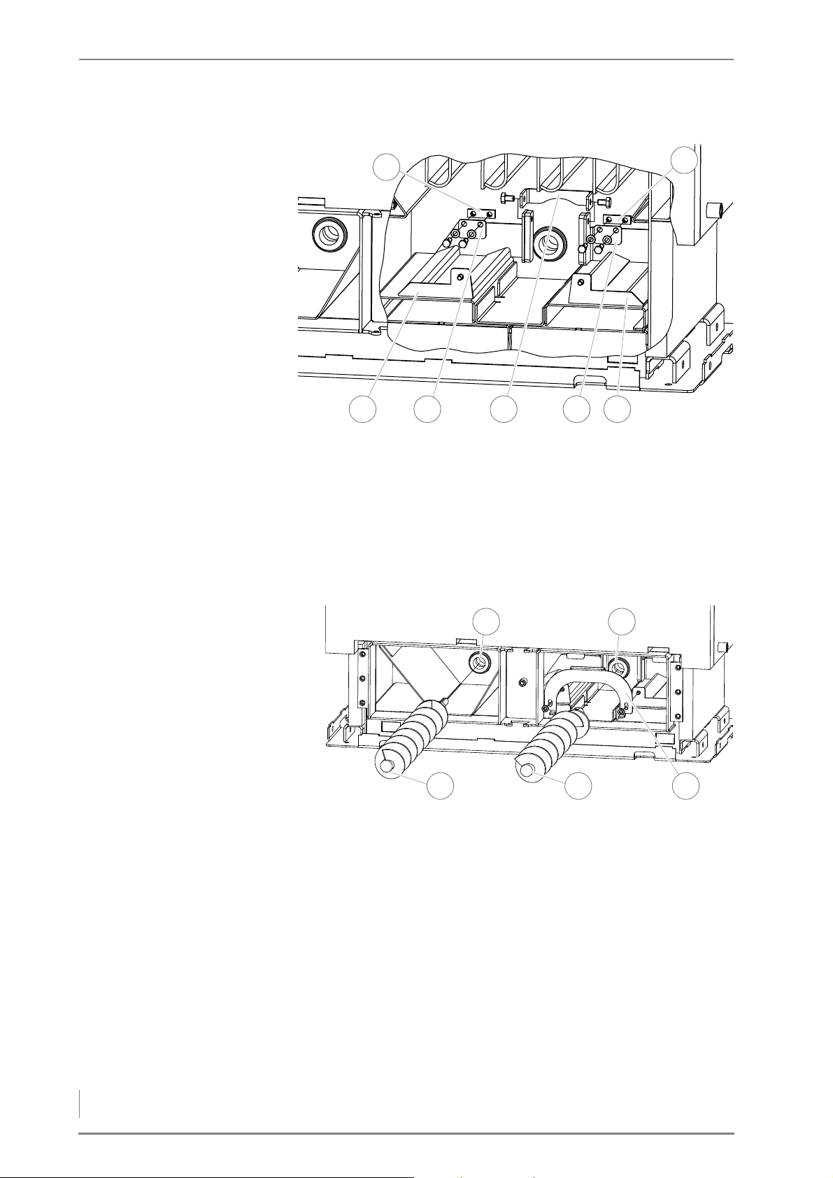
4 Planning and installation – Installing the heating system
7. Fit the left (1) and the right (3) tray on the centre tray (2).
7
6
1 32 54
43 5
1 2
Figure 4/19 - Installing the ash walking floor delivery system
8. Fit the two moving ash floors (1 + 5) on the trays.
9. Connect the two moving ash floors (1 + 5) by means of the bracket
(3) with the M10 screws (17 mm).
NSTALLING THE ASH REMOVAL
I
AUGER
10.Install the two guide plates (2 + 4) with the M8 screws (13 mm)
with the spacer plates (6 + 7) underneath.
Figure 4/20 - Installing the ash removal auger
11.Install the bracket (5) on the moving ash floor with M10 screws (17
mm).
12.Insert the ash removal auger with the long shaft end (3) from the
front on the feed side through the opening (1) provided for this.
13.Insert the second ash removal auger with the short shaft end (4)
through the opening (2) provided for this.
48
Page 49
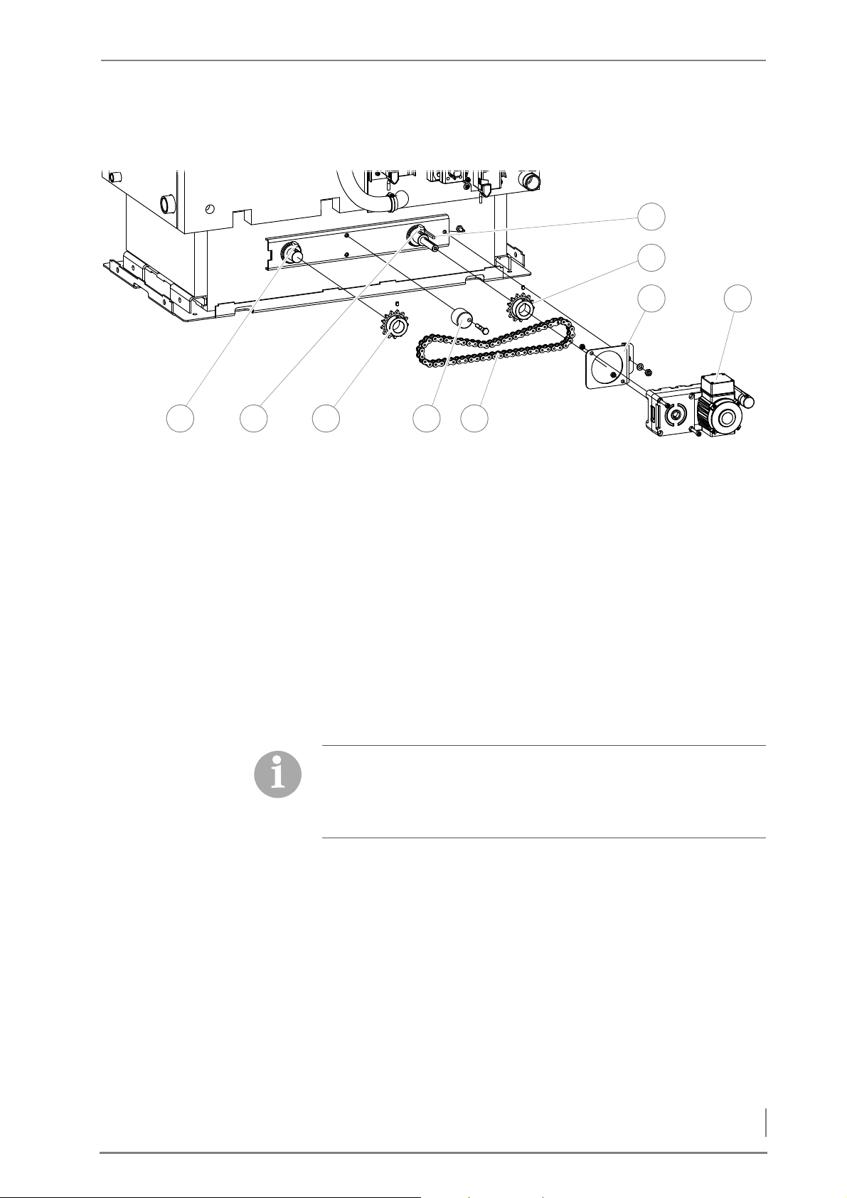
4 Planning and installation – Installing the heating system
MOUNTING THE ASH REMOVAL
32
7
4 5
8 9
6
1
MOTOR
Figure 4/21 - Installing the ash removal system
14.Place the two small feather keys (1 + 2) in the recesses provided for
them on the auger shafts.
15.Align the sprockets (3 + 7) flush on the auger shafts and fasten
them with the two M8 hexagon socket screws (4 mm).
C
ONNECTING THE ASH REMOVAL
MOTOR
16.Place the feather key (6) in the recess provided on the feed side
auger shaft.
17.Mount the drive chain (5) on the two sprockets (3 + 7).
18.Fasten the ash removal motor (9) with the M8 hexagon socket
screws (6 mm) on the torque support (8).
19.Insert the ash removal motor (9) with the torque support (8) on the
feed side auger shaft and fasten the support plate onto the boiler
with the nut (M10, 17 mm).
For the version of the boiler with the feeding system on the left side,
the chain tensioner must be fastened in the upper position.
For the version of the boiler with the feeding system on the right
side, the chain tensioner must be fastened in the lower position.
20.Mount the chain tensioner (4) on the boiler with the M10 screw
(size 17).
21.Check the tension of the drive chain in the chain’s middle and use
the chain tensioner if necessary to correct the amount of play.
✎ The drive chain can have about 1 cm of play upward or downward.
22.Lay the ash removal motor cable in such a way that it cannot con-
tact the drive chain.
23.Connect the plug of the ash removal motor to the drive module.
✎ See “Electrical plans HDG Compact 25 - 80”.
49
Page 50
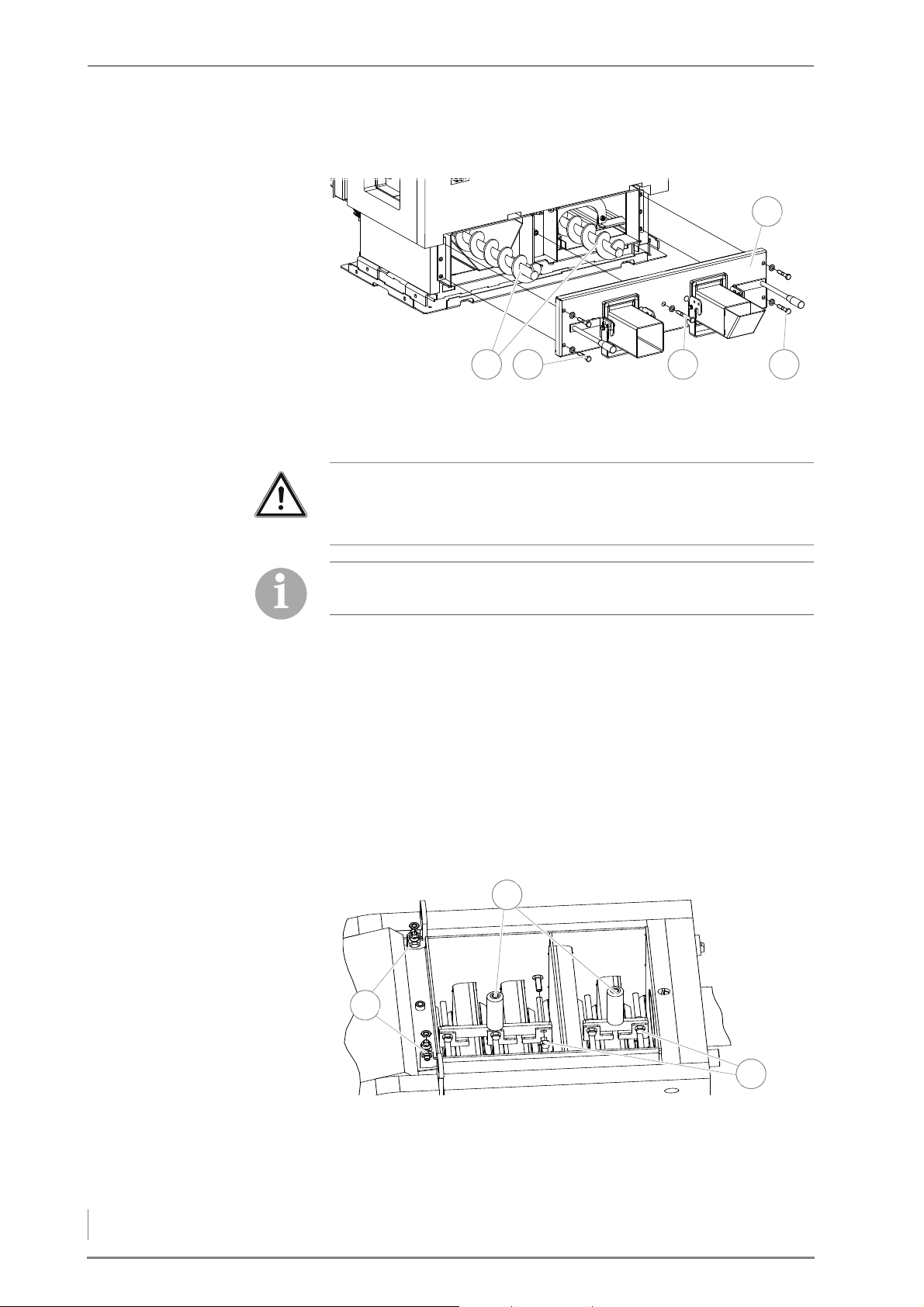
4 Planning and installation – Installing the heating system
MOUNTING THE ASH REMOVAL
5
1 42 3
1
3
2
DOOR
Figure 4/22 - Mounting the ash removal door
24.Slide the ash removal door (5) onto the two ash removal
augers (1).
Important!
The two ash removal augers must not come into contact with the
ash removal door when installed.
Because of the soft seal, the screws should not be screwed in up to
the stop. Only tighten until a resistance is detected.
25.Tighten the ash removal door (5) with the long screw (3) and four
short M12 screws (2 + 4) (19 mm) and the M12 washers evenly.
26.If necessary, align the ash removal augers (1) with the screws of
the ash removal door (2 + 4).
✓ The ash removal system is installed.
INSTALLING THE HEAT EXCHANGER CLEANER
INSTALLING THE CROSSBEAMS 1. Release the pre-mounted M12 nuts (size 19) from the short or long
crossbeam.
Figure 4/23 - Installing the crossbeams
2. Place the two crossbeams (1) on the turbulators in the cleaning
50
shaft.
Page 51
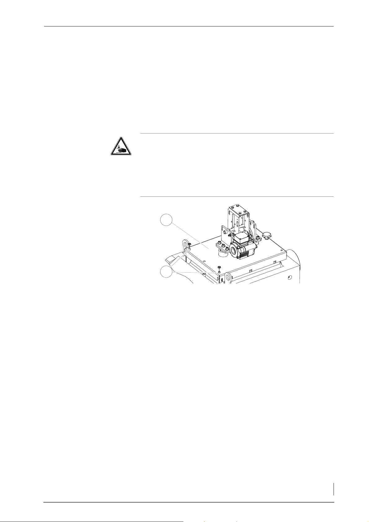
4 Planning and installation – Installing the heating system
M
1
2
OUNTING THE CLEANING
SHAFT LID
3. Bolt the crossbeams (1) onto the turbulators with the M12 (19
mm) screws (3) and allow about 2mm clearance between nuts and
turbulator/crossbeam retainer.
4. Lock the M12 nuts with the 19 mm M12 lock nuts.
5. Unscrew the two 19 mm M12 nuts on the hinges (2) of the
cleaning shaft lid on the boiler.
6. Fold up the hinges (2).
Warning!
Danger of injury
The cleaning shaft lid is very heavy. Hands can become crushed
when installing it.
Always take care not to grasp under the cleaning shaft lid when
putting it on.
Figure 4/24 - Putting on the cleaning shaft lid
7. Place the cleaning shaft lid (1) on the boiler.
8. Guide the screws (2) of the hinges into the holes on the cleaning
shaft lid (1).
9. Bolt on the cleaning shaft lid (1) with the M12 nuts on the hinges
using a 19 mm spanner.
51
Page 52
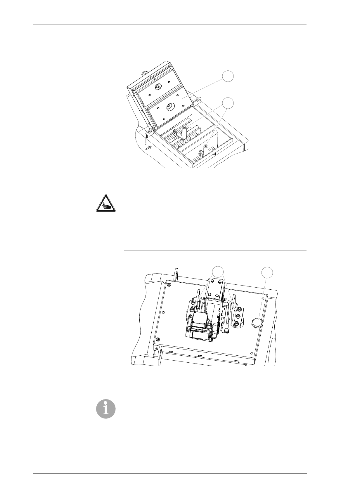
4 Planning and installation – Installing the heating system
10.Open the cleaning shaft lid (1).
1
2
1
2
Figure 4/25 - Aligning the crossbeams
11.Align the crossbeams (2) centred to the boiler inner walls.
Warning!
Danger of injury
The cleaning shaft lid is very heavy and can fall shut. Hands and
arms can thereby be crushed.
Take care not to bump into the opened cleaning shaft lid and cause
it to fall shut.
12.Slowly close the cleaning shaft lid (1).
Figure 4/26 - Fastening the crossbeams on the cleaning shaft lid
13.Bolt the crossbeams onto the cleaning shaft lid with the two
middle 10 mm M12 hexagon socket screws (1).
Tighten the two hexagon socket screws of the cleaning shaft lid.
Then turn the screws a quarter-turn back in the opposite direction.
14.Tighten the star-grip screw (2).
52
Page 53
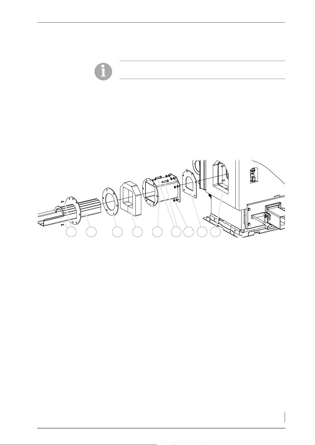
4 Planning and installation – Installing the heating system
CONNECTING THE HEAT
42 3 6 7 8 951
EXCHANGER CLEANER
INSTALLING THE FEED CHANNEL
AND ADAPTER PIPE
15.Lay the cable of the cleaning system motor and the limit switch
along the insulation to the drive module.
When laying the cable, ensure that there is enough cable for the
cleaning shaft lid to be opened.
16.Connect the plug of the heat exchanger cleaner to the central
module.
✎ See “Electrical plans HDG Compact 25 - 80”.
✓ The heat exchanger cleaner is now installed.
INSTALLING THE FEEDING SYSTEM AND PRESSURE EQUALISATION HOSE
Figure 4/27 - Attaching the feed channel and adapter pipe
1. Place the seal (8) on the connection to the boiler (9).
2. Install the feed channel (5) with the washers and M12 nuts (size
19) on the connection to the boiler (9).
3. Slide the insulation (4) via the feed channel (5).
4. Slide the adapter pipe (2) with the seal (3) into the
feed channel (5).
5. Align the seal (3) with the holes through the adapter (2) and the
feed channel (5).
6. Insert the M12 screws (6) through the holes in the adapter (2) and
the feed channel (5) from the boiler side.
7. Poke a hole through the seal (3) at the top and bottom for the
centering screws (1).
8. Insert the centering screws (1) through the holes in the
adapter (2) and the feed channel (5) and secure them with the
nut M6 (size 10).
53
Page 54
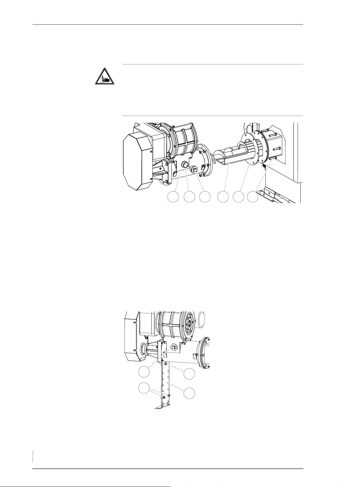
4 Planning and installation – Installing the heating system
INSTALLING THE FEEDING
54321 6
3
1
4
2
SYSTEM
Warning!
Danger of injury
The feeding system is very heavy. Hands and feet could be crushed
when it is lifted.
Only lift the feed system using suitable lifting equipment.
Figure 4/28 - Attaching the feeding system
9. Slide the second seal (5) onto the adapter pipe (4).
I
NSTALLING THE SUPPORT LEG
10.Slide the feeding system (1) into the adapter pipe (4).
11.Insert the M12 screws (6) through the adapter tube (4) and
feeding system (1) from the boiler side.
12.Secure the M12 screws (6) with M12 nuts (size 19).
13.If applicable remove the connection bush (2), for the pressure
equalization tube, from the front of the feeding system (1).
14.Fit the DN40 plug (3) in to the front equalisation tube connection
(2) on the feeding system.
15.Fit the support leg (4) with a
19 mm M12 screw (3) onto the
feeding system (1).
16.Secure the support leg (4) to
the floor. (anchor srews are
not included in the scope of
the delivery).
17.Secure the two parts of the
support leg (4) with the two
M10 screws (size 17) (2).
Figure 4/29 - Fitting the support leg
54
Page 55
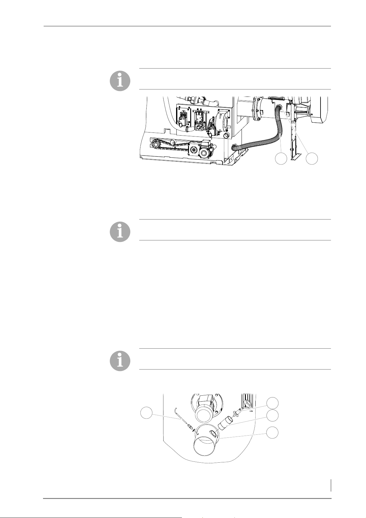
4 Planning and installation – Installing the heating system
ATTACHING THE PRESSURE
21
2
1
3
4
EQUALISATION HOSE
The pressure equalisation hose is only available with the
HDG Compact 45/50/65/80 boiler.
Figure 4/30 - Attaching the pressure equalisation hose
18.Place the rubber seal on the feed side connections of the pressure
equalisation hose (1).
19.Attach the pressure equalisation hose (1) to the connection
bushing of the feeding system (2) using a pipe wrench.
The pressure equalisation hose can only be installed once the cladding has been installed.
C
ONNECTING THE FEEDING
SYSTEM
ISMANTLING THE FLUE GAS
D
TEMPERATURE SENSOR AND
LAMBDA SENSOR
✓ The pressure equalisation hose is connected on the feed side.
20.Insert the feeding system cable through the opening provided for
it on the cladding.
21.Connect the plug of the feeding system to the drive module.
✎ See “Electrical plans HDG Compact 25 - 80”.
✓ The feeding system and the pressure equalisation hose are now
installed.
INSTALLING THE CLADDING HDG COMPACT 25/35
The cladding packets are numbered chronologically. The number
also corresponds to the order in which the cladding part is needed.
Figure 4/31 - Dismantling the flue gas temperature sensor and lambda sensor
55
Page 56
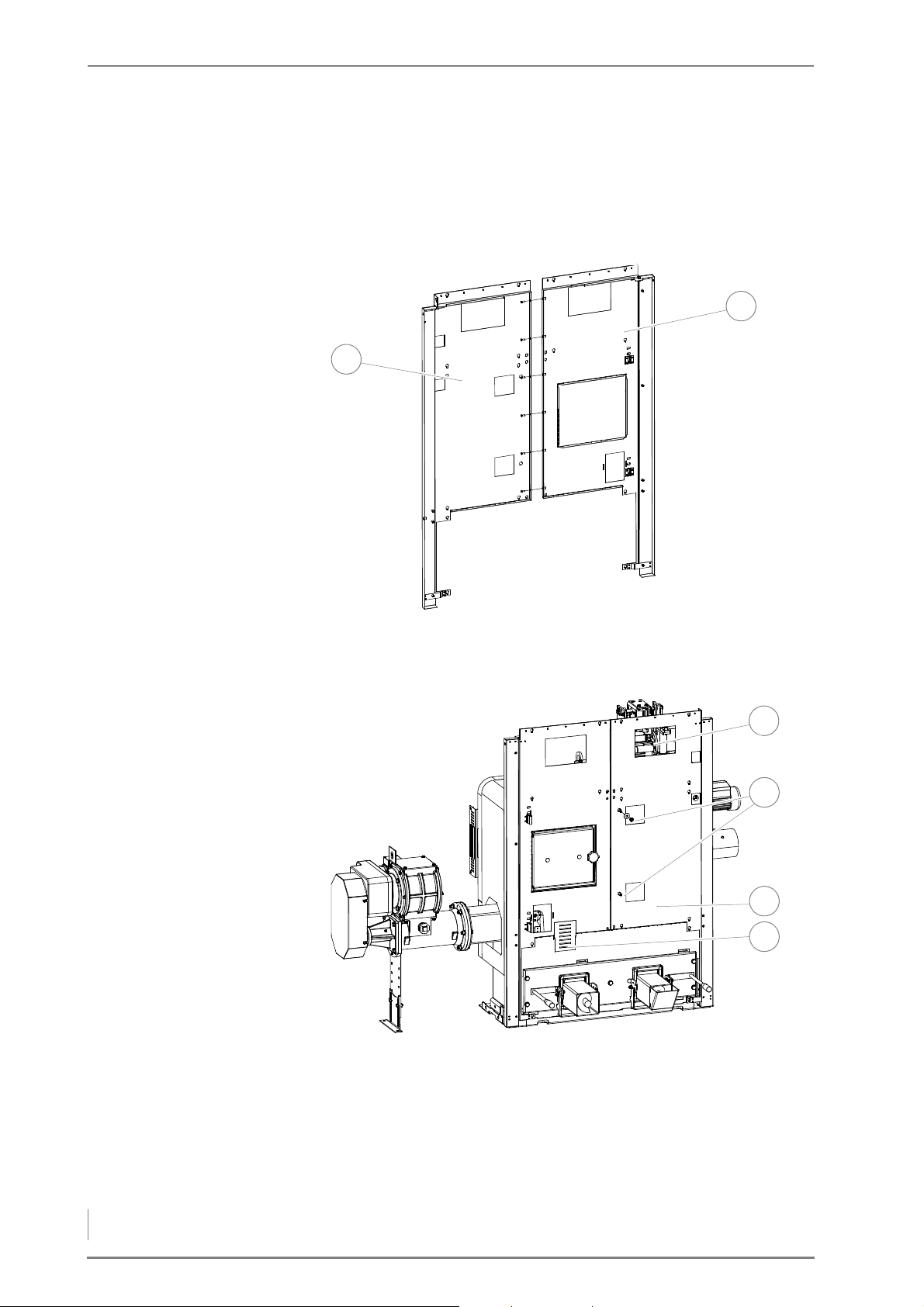
4 Planning and installation – Installing the heating system
I
2
1
4
3
1
2
NSTALLING THE FRONT
CLADDING
1. Dismantle the preinstalled flue gas temperature sensor (1) to-
gether with the M10 (size 17) clamp screw, the lambda sensor (2)
and the connection pieces (3) from the flue gas pipe
connection (4).
2. Open cladding packet “1A”.
Figure 4/32 - Fitting the front cladding
3. Screw the two front claddings (1 + 2) together using the M6 hex-
agon socket screws (size 4).
Figure 4/33 - Installing the front cladding
4. Fasten the front cladding (3) on the boiler with the M10 (size 17)
(2) nuts and M10 washers.
5. Insert the cover plate (4) for the level indicator in the front clad-
6. Thread the connection cable for the control unit HDG Control
56
ding (3).
Touch through the recess (1) in the front cladding.
Page 57
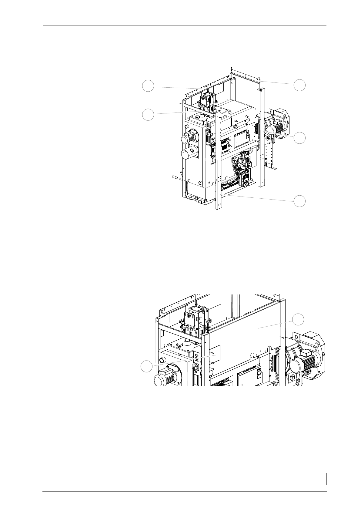
4 Planning and installation – Installing the heating system
INSTALLING THE CORNER
3
2
4
5
1
1
2
SUPPORTS
Figure 4/34 - Installing the corner supports and connecting plates
7. Install the connecting plate (2) on the flue pipe side between the
front cladding (1) and the corner support (5) using the M6 hexagon sockets screws (size 4).
8. Install the connecting plate (3) on the feed side between the front
cladding (1) and the corner support (4) with the M6 hexagon
sockets screws (size 4).
I
NSTALLING THE UPPER REAR
CLADDING
Figure 4/35 - Installing the upper rear cladding
9. Install the upper rear cladding (1) between the two corner sup-
ports with the M6 hexagon socket screws (size 4).
10.Leave the recess (2) in the rear cladding (1) free to be wired to the
mains supply later, if necessary.
57
Page 58
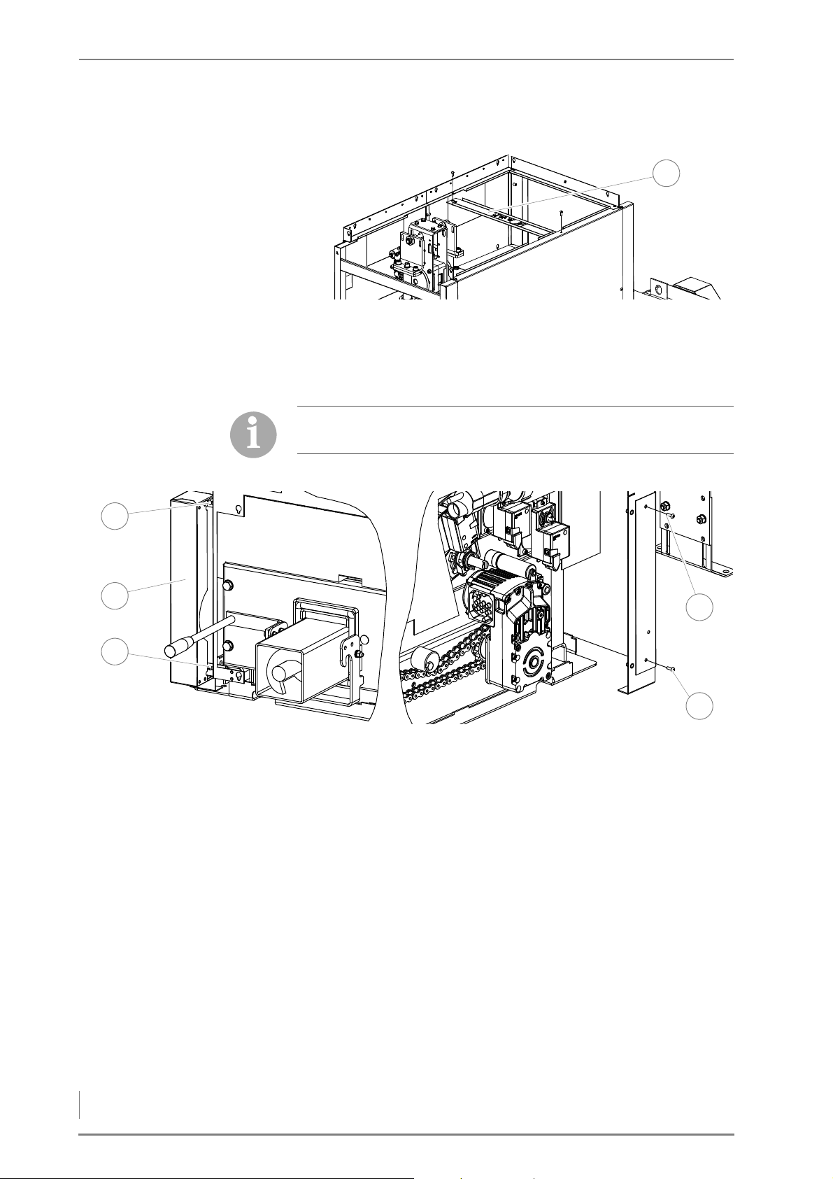
4 Planning and installation – Installing the heating system
INSTALLING THE CONNECTING
1
2
1
3
5
4
PLATE
I
NSTALLING THE SIDE CLADDING
Figure 4/36 - Installing the middle connecting plate
11.Install the middle connecting plate (1) between the front cladding
(1) and the upper rear cladding with the M6 hexagon sockets
screws (size 4).
Ensure that the clearances always run parallel when installing the
cladding.
12.Open cladding packet “2”.
Figure 4/37 - Installing the side cladding on the feed side
13.Attach the lower side cladding (2) on the feed side to the front
cladding with the M6 hexagon socket screws (size 4) (1 + 3).
14.Attach the lower side cladding (2) on the feed side to the rear
corner support with the M6 hexagon socket screws (size 4) (4 + 5).
58
Page 59
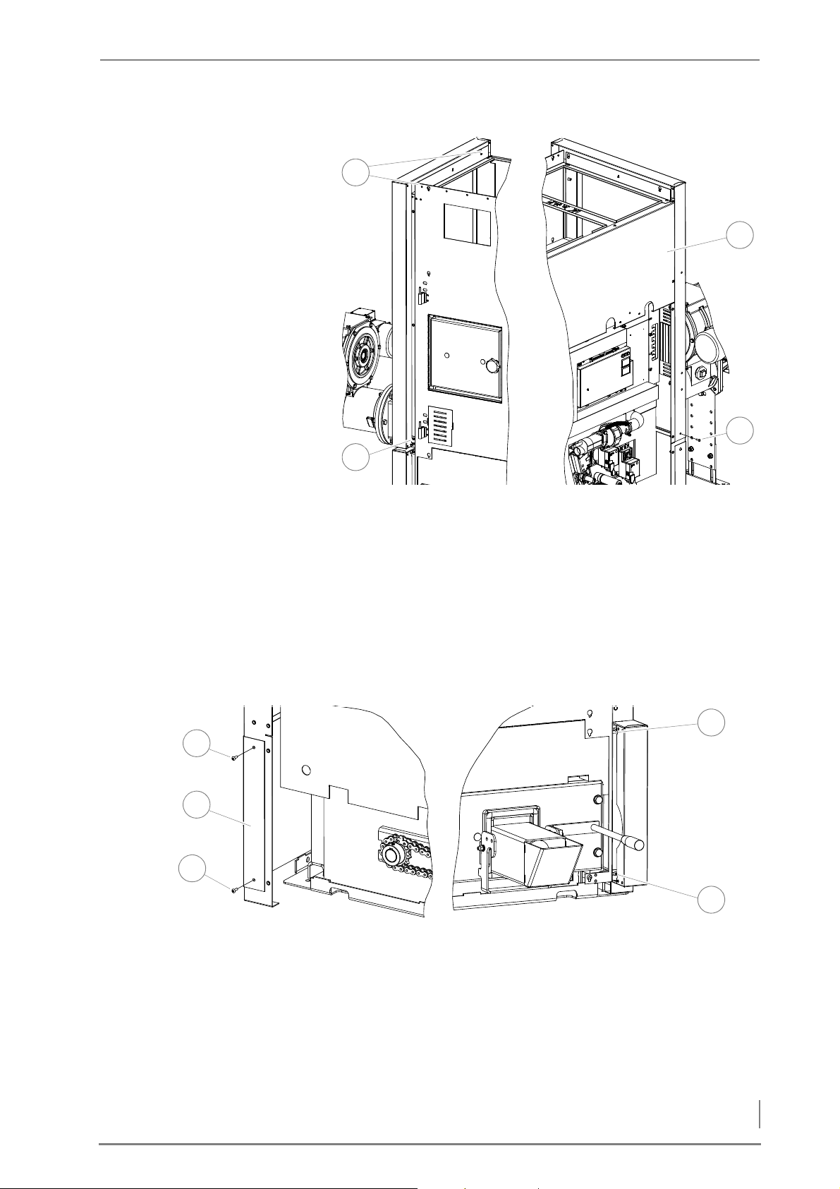
4 Planning and installation – Installing the heating system
Figure 4/38 - Installing the side cladding on the feed side at the top
3
4
1
2
1
2
5
3
4
15.Hang the upper side cladding (2) on the feed side with the pre-as-
sembled M6 Hexagon socket screws (1) (size 4) to the connection
plate.
16.Fasten the upper side cladding (2) on the feed side at the bottom
to the front cladding with the M6 Hexagon socket screws (3) (size
4)
17.Secure the upper side cladding (2) on the feed side at the bottom
to the rear corner support using the M6 Hexagon socket
screws (4) (size 4).
Figure 4/39 - Installing the side cladding on the flue gas pipe side at the bottom
18.Fasten the lower side cladding (4) on the flue side to the front
cladding with the M6 Hexagon socket screws (3+5) (size 4).
19.Secure the lower side cladding (4) on the flue side to the rear
corner support using the M6 Hexagon socket screws (1+2).
59
Page 60
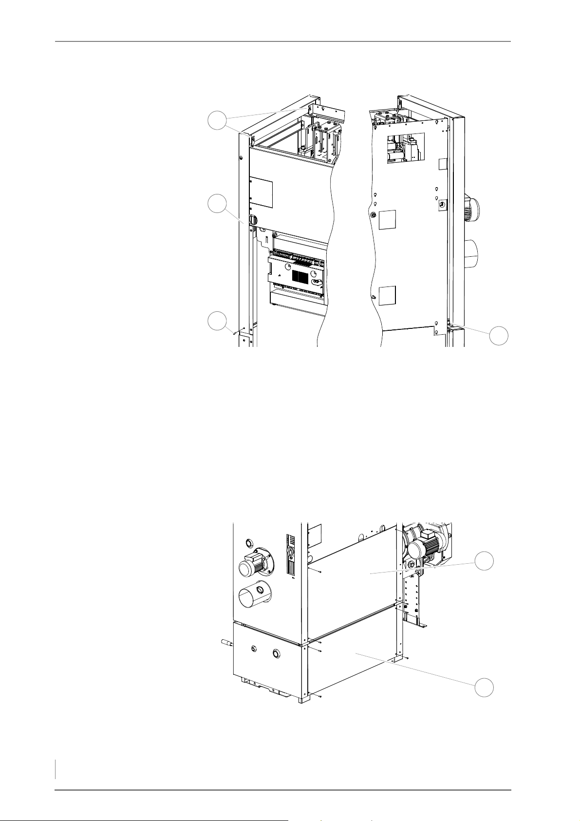
4 Planning and installation – Installing the heating system
Figure 4/40 - Installing the side cladding on the flue gas pipe side at the top
4
1
2
3
2
1
20.Hang the upper side cladding (3) on the flue side with the pre-as-
sembled M6 Hexagon socket screws (1) (size 4) onto the front and
rear cladding.
21.Secure the upper side cladding (3) on the flue side at the bottom
to the front cladding using the M6 Hexagon socket
screw (4) (size 4)
22.Fasten the upper side cladding (3) on the flue side at the bottom
to the rear corner support with the M6 Hexagon socket
screw (2) (size 4).
I
NSTALLING THE REAR
CLADDING
Figure 4/41 - Installing the rear cladding
23.Install the lower rear cladding (2) with the M6 hexagon socket
60
screws (size 4) to the corner supports.
Page 61
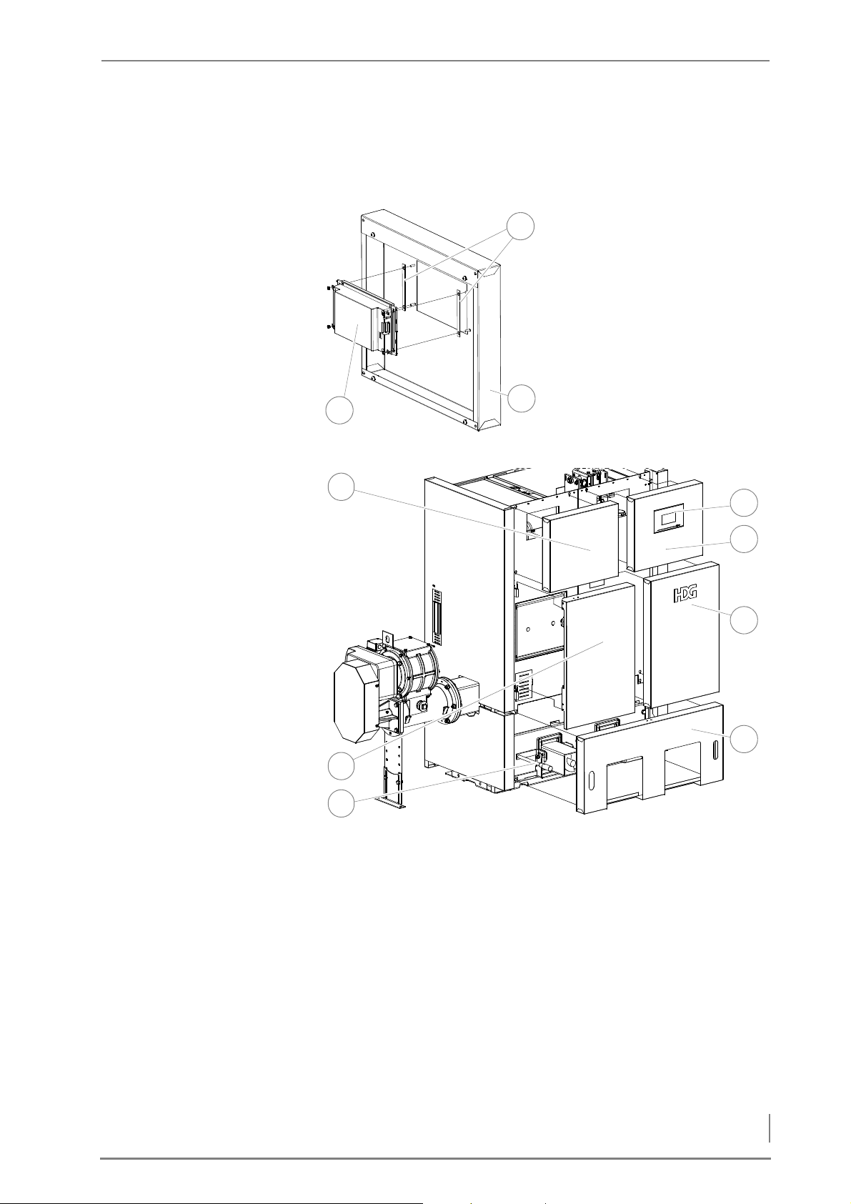
4 Planning and installation – Installing the heating system
I
1
1
3
2
6
5
4
1
7
3
2
NSTALLING THE FRONT
CLADDING
24.Install the upper rear cladding (1) with the M6 hexagon socket
screws (size 4) to the corner supports.
25.Open cladding packet “4”.
26.Install the control unit
HDG Control Touch (1) with
the spacers (2) in the cladding
panel (3) with the washers
and M4 screws (size 7).
Figure 4/42 - Mounting the control unit
Figure 4/43 - Installing the cladding on the front side
27.Place the front door (2) onto the hinges on the front cladding.
28.Hang the cladding panel (6) with the logo on using the pre-assem-
bled M6 Hexagon socket screws onto the front cladding.
29.Position both ash box levers to horizontal.
30.Hang the lower front panel (7) onto the front cladding using the
pre-assembled M6 hexagon socked screws.
31.Connect the HDG Touch wiring according to the circuit diagram.
✎ See “Electrical plans HDG Compact 25 - 80”.
32.Hang the upper front panel (5), with the HDG Touch control at-
tached, onto the front cladding using the pre-assembled M6 hexagon socked screws.
61
Page 62
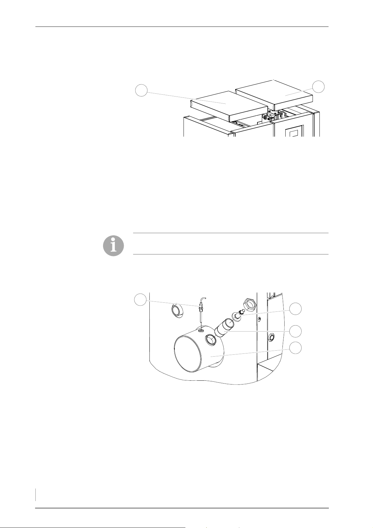
4 Planning and installation – Installing the heating system
I
1
2
3
1
4
2
NSTALLING THE TOP COVERS
33.Hang the upper front panel on the feed side (1) using the pre-as-
sembled M6 hexagon socked screws.
Figure 4/44 - Installing the top covers
34.Place the heat exchanger cleaner cover (2) onto the connecting
plates.
35.35.Place the top panel on the feed side (1) on the connecting
plates.
✓ The cladding is installed.
INSTALLING THE CLADDING HDG COMPACT 45/50/65/80
DISMANTLING THE FLUE GAS
TEMPERATURE SENSOR AND
LAMBDA SENSOR
The cladding packets are numbered chronologically. The number
also corresponds to the order in which the cladding part is needed.
Figure 4/45 - Dismantling the flue gas temperature sensor and lambda sensor
1. Dismantle the preinstalled flue gas temperature sensor (1) to-
gether with the M10 (size 17) clamp screw, the lambda sensor (2)
and the connection pieces (3) from the flue gas pipe connection
(4).
62
Page 63
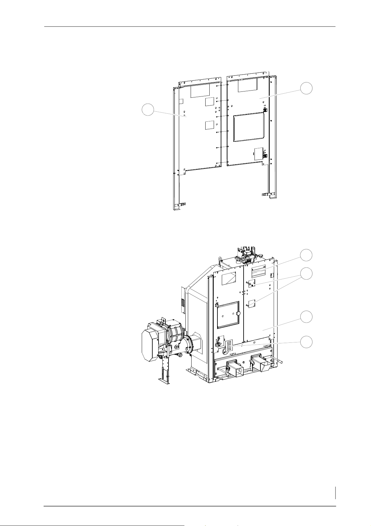
4 Planning and installation – Installing the heating system
INSTALLING THE FRONT
2
1
4
3
1
2
CLADDING
2. Open cladding packet “1A”.
Figure 4/46 - Fitting the front cladding
1. Screw the two front claddings (1 + 2) together using the M6 hex-
agon socket screws (size 4).
Figure 4/47 - Installing the front cladding
2. Fasten the front cladding (3) to the boiler with the M10 (size 17) (2)
3. Insert the cover plate (4) for the level indicator in the front clad-
nuts and M10 washers.
ding (3).
4. Thread the connection cable for the control unit HDG Control
Touch through the recess (1) in the front cladding.
63
Page 64
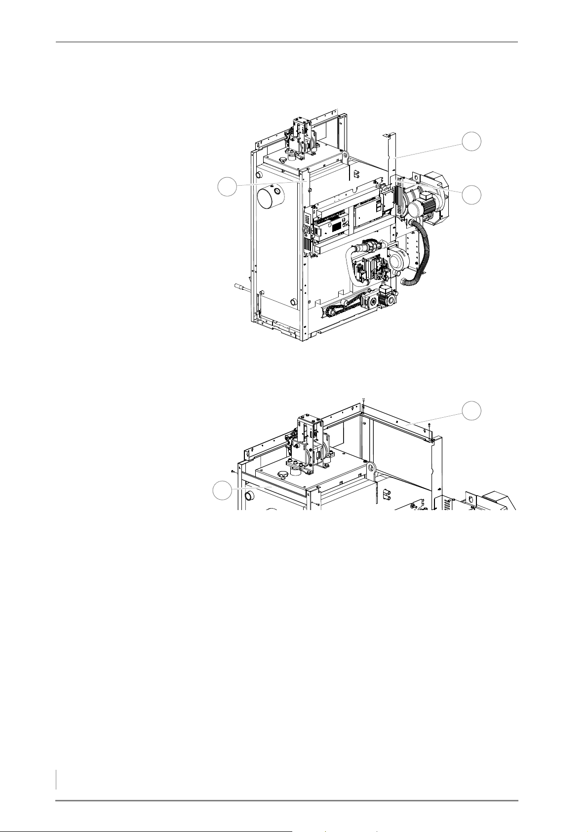
4 Planning and installation – Installing the heating system
INSTALLING THE CORNER
2
1
3
2
1
SUPPORTS
Figure 4/48 - Installing the corner supports
5. Slide the two corner supports (1 + 2) behind the circuit board as-
sembly plate (3).
Figure 4/49 - Installing the outer connecting plate
6. Install the connecting plate (1) on the flue pipe side between the
front cladding and the corner support using the M6 hexagon
sockets screws (size 4).
7. Install the connecting plate (2) on the flue pipe side between the
front cladding and the corner support using the M6 hexagon
sockets screws (size 4).
64
Page 65
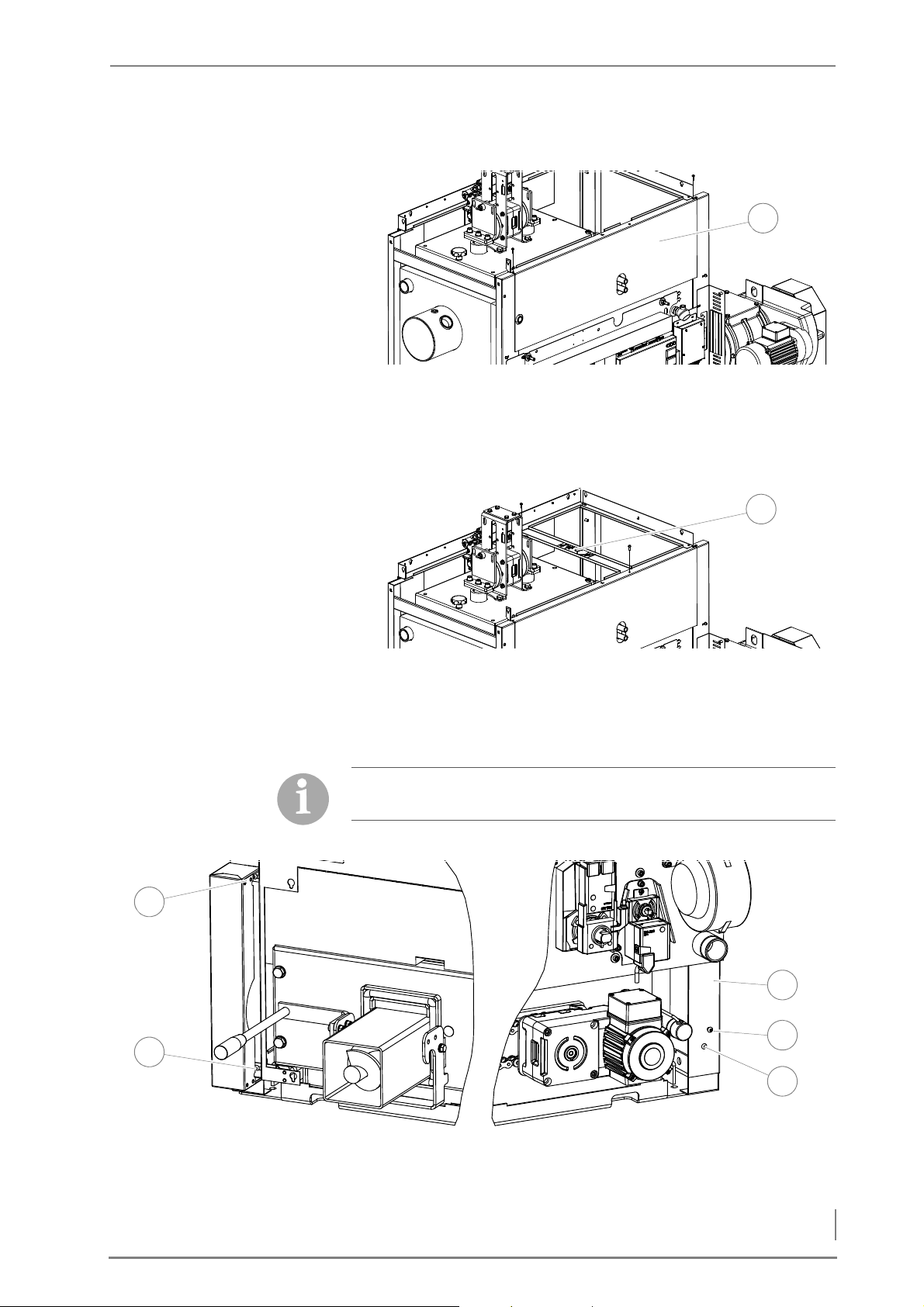
4 Planning and installation – Installing the heating system
INSTALLING THE UPPER REAR
1
1
1
3
5
4
2
CLADDING
I
NSTALLING THE CONNECTING
PLATE
Figure 4/50 - Installing the upper rear cladding
8. Install the upper rear cladding (1) between the two corner sup-
ports with the M6 hexagon socket screws (size 4).
Figure 4/51 - Installing the middle connecting plate
9. Install the middle connecting plate (1) between the front cladding
and the upper rear cladding with the M6 hexagon sockets screws
(size 4).
I
NSTALLING THE SIDE CLADDING
Ensure that the clearances always run parallel when installing the
cladding.
10.Open cladding packet “2”.
Figure 4/52 - Installing the side cladding on the feed side
11.Attach the lower side cladding (2) on the feed side to the front
cladding with the M6 hexagon socked screws (size 4) (1 + 3).
65
Page 66
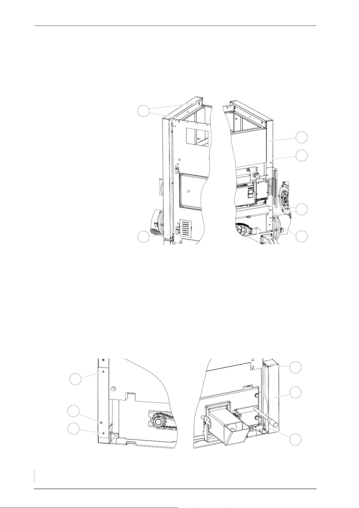
4 Planning and installation – Installing the heating system
12.Attach the lower side cladding (2) on the feed side to the rear
3
6
4
5
1
2
5
1
3
6
4
2
corner support with the M6 hexagon socket screws (5) (size 4).
13.Screw the M6 hexagon socket screw (4) (size 4) loosely into the
side cladding so that the rear cladding can be attached later.
Figure 4/53 - Installing the side cladding on the feed side at the top
14.Hang the upper side cladding (2) on the feed side on the outer
connecting plate with the pre-assembled M6 hexagon socket
screws (1) (size 4).
15.1Fasten the upper side cladding (2) on the feed side at the bottom
to the front cladding with the M6 Hexagon socket
screws (3) (size 4).
16.Secure the upper side cladding (2) on the feed side at the bottom
to the rear corner support using the M6 Hexagon socket screws (4)
(size 4).
17.Screw the M6 hexagon socket screw (5) (size 4) loosely into the
side cladding so that the rear cladding can be attached later.
Figure 4/54 - Installing the side cladding on the flue gas pipe side at the bottom
66
Page 67
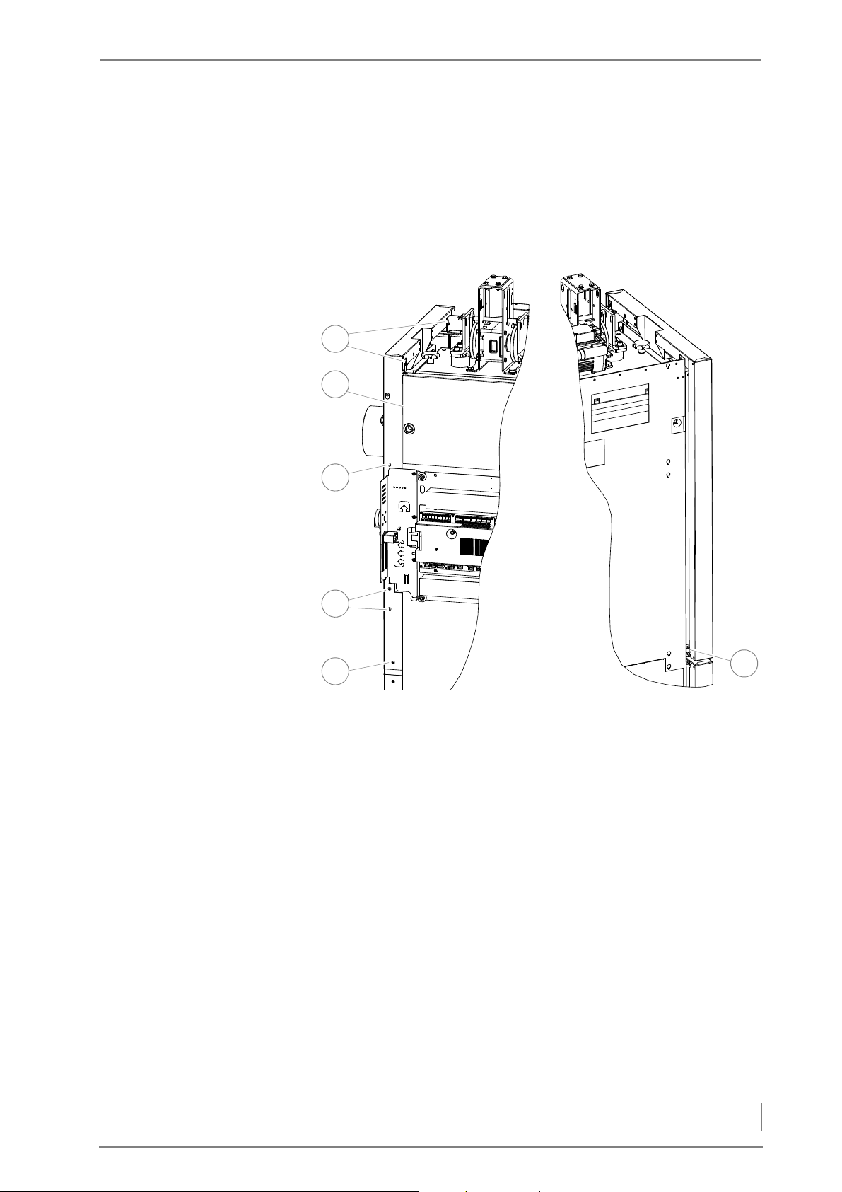
4 Planning and installation – Installing the heating system
18.Fasten the lower side cladding (5) on the flue side to the front
2
6
1
4
3
5
cladding using the M6 Hexagon socket screws (4+6) (size 4).
19.Secure the lower side cladding (5) to the rear corner support using
the M6 Hexagon socket screws (1+3) (size 4).
20.Screw the M6 Hexagon socket screw (2) (size 4) loosely into the
lower side cladding (5) so that the rear cladding can be attached
later.
Figure 4/55 - Installing the side cladding on the flue gas pipe side at the top
21.Hang the flue side upper side cladding (5) onto the front cladding
and rear cladding using the pre-assembled M6 Hexagon socket
screws (1) (size 4).
22.Secure the upper side cladding (5) on the flue side at the bottom
to the front cladding with the M6 Hexagon socket
screw (6) (size 4).
23.Fasten the upper side cladding (5) on the flue side at the bottom
to the rear corner support with the M6 Hexagon socket
screw (4) (size 4).
24.Screw the M6 Hexagon socket screw (3) (size 4) loosely into the
upper side cladding (5), at the bottom, so that the rear cladding
can be attached later.
67
Page 68
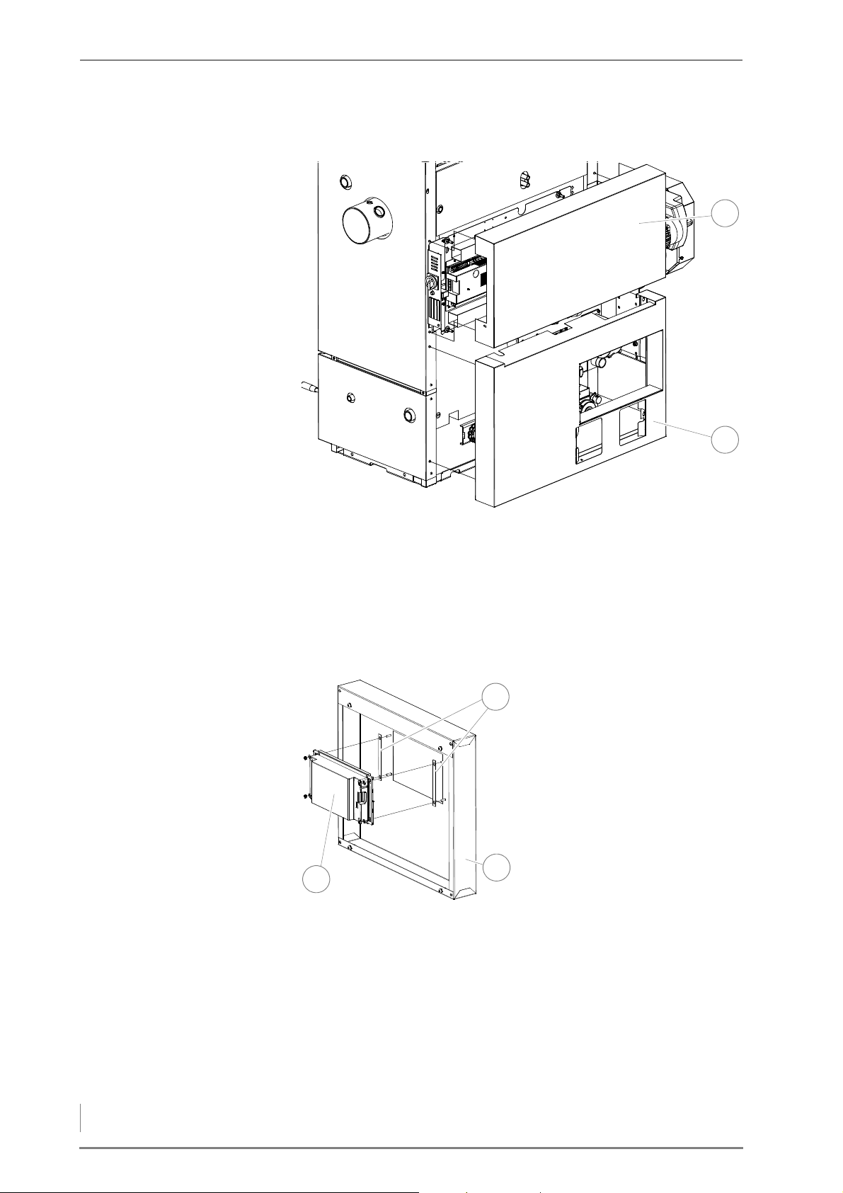
4 Planning and installation – Installing the heating system
INSTALLING THE REAR
2
1
1
1
3
2
CLADDING
25.Open cladding packet “1B”.
Figure 4/56 - Installing the rear cladding
I
NSTALLING THE FRONT
CLADDING
26.Hang the lower rear cladding (2) on to the preassembled M6 hex-
agon socket screws.
27.Hang the upper rear cladding (1) on to the preassembled M6 hex-
agon socket screws.
28.Open cladding packet “4”.
29.Install the control unit HDG
Control Touch (1) with the
spacers (2) in the cladding
panel (3) with the washers
and M4 screws (size 7).
Figure 4/57 - Mounting the control unit
68
Page 69
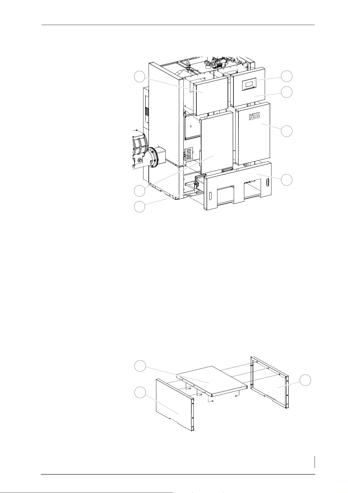
4 Planning and installation – Installing the heating system
Figure 4/58 - Installing the cladding on the front side
6
5
4
1
7
3
2
1
2
3
30.Place the front door onto the hinges on the front cladding.
31.Hang the cladding panel (6) with the logo onto the front cladding
with the pre-assembled M6 hexagon socket screws.
32.Set the ash box clamp handles (3) in the horizontal position.
33.Hang the ash removal cladding panel (7) onto the front cladding
with the pre-assembled M6 hexagon socket screws.
34.Connect the HDG Touch control wiring in accordance with the
wiring diagram.
35.Hang the cladding panel (5) with the HDG Touch attached onto
the front cladding with the pre-assembled M6 hexagon socket
screws.
36.Hang the upper feed side cladding panel (1) onto the front clad-
ding with the pre-assembled M6 hexagon socket screws.
I
NSTALLING THE TOP COVERS
Figure 4/59 - Fitting the heat exchanger cleaner cover
69
Page 70
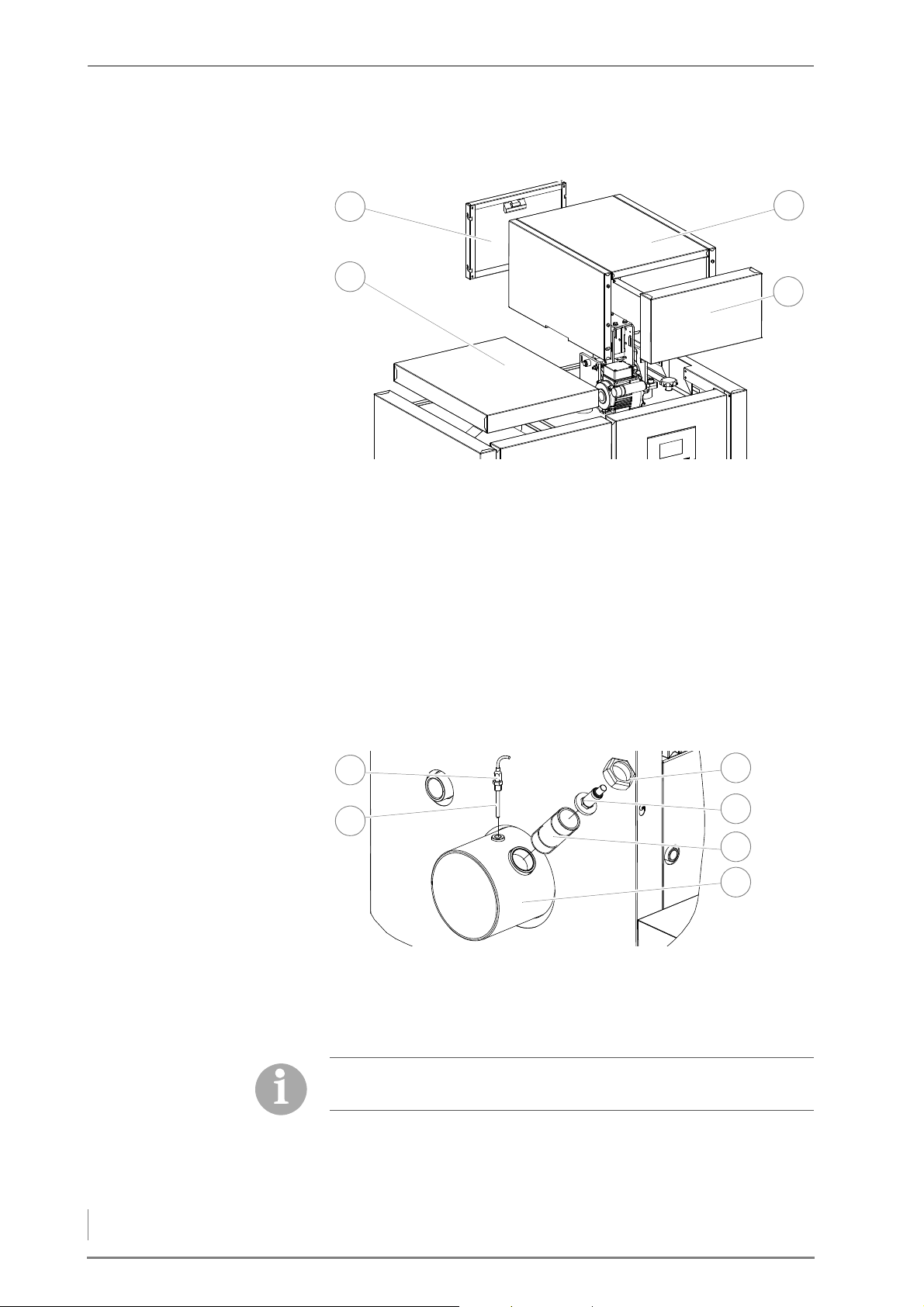
4 Planning and installation – Installing the heating system
37.Screw the two side parts (2 + 3) to the middle part (1) using the M6
1
2
3
4
5
1
6
2
4
3
hexagon socket screws (size 4).
Figure 4/60 - Installing the top covers
38.Place the assembled sides and top (3) over the cleaning mecha-
nism onto the connecting plates.
39.Hang the front and rear panels (4 + 1 respectively) onto the top
and sides (3).
40.Place the feed side top cover (2) onto the connecting plates.
✓ The cladding is installed.
INSTALLING THE FLUE GAS TEMPERATURE SENSOR AND LAMBDA
SENSOR
Figure 4/61 - Installing the flue gas temperature sensor and lambda sensor
1. Fit the M10 clamp screw (size 17) (2) and M10 washer in the flue
gas pipe connection (6).
2. Slide the flue gas temperature sensor (1) into the clamp screw (2).
The flue gas temperature sensor must be installed so that the
sensor element projects approx. 2 cm out of the clamp screw.
3. Fasten the flue gas temperature sensor (2) by tightening the M10
70
clamp nut (size 17) (1).
Page 71
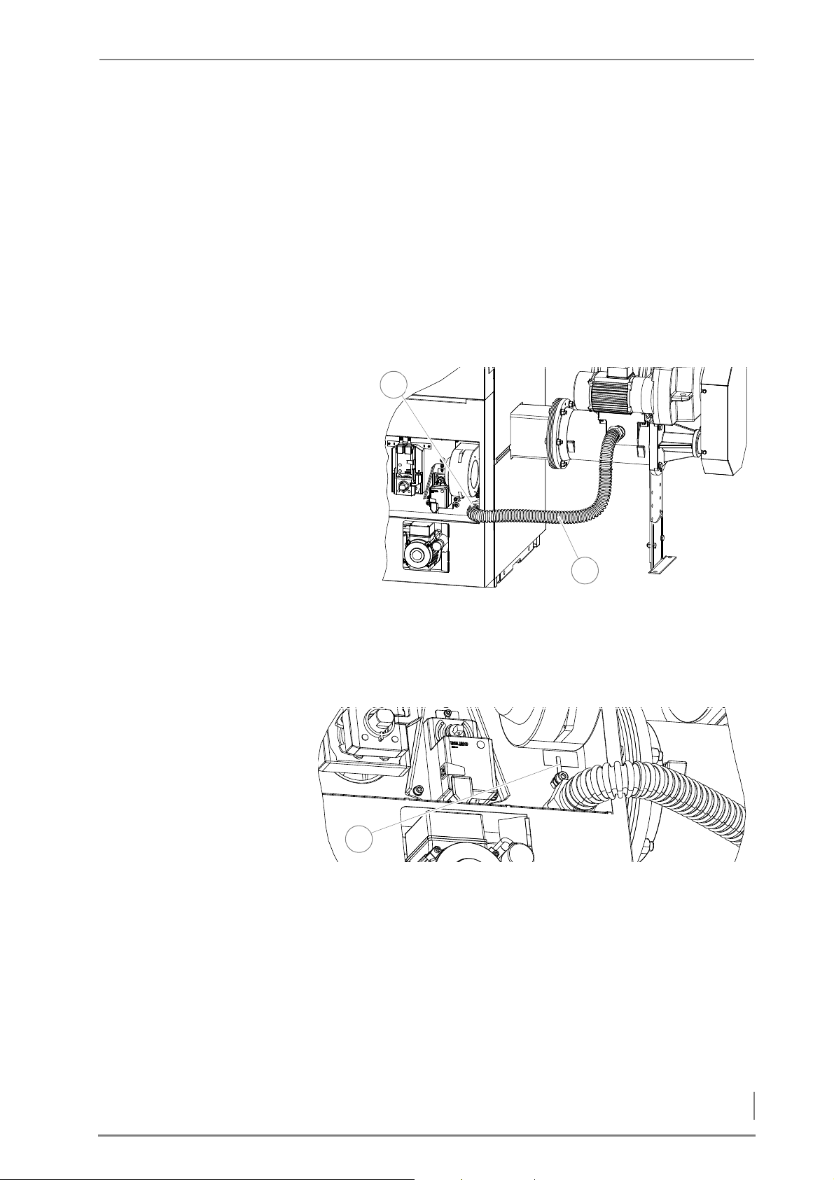
4 Planning and installation – Installing the heating system
4. Screw the DN40 nipple (5) into the flue gas pipe connection with
1
2
Z
u
A
u
f
1
a pipe wrench.
5. Place the lambda sensor (4) in its ceramic disc onto the DN40
nipple (5).
6. Fasten the lambda sensor (4) to the DN40 nipple by screwing the
nut (3) down onto the ceramic disc.
✓ The flue gas temperature sensor and the lambda sensor are now
installed.
ATTACHING THE PRESSURE EQUALISATION HOSE
Figure 4/62 - Installing the pressure equalising hose
7. Place the rubber seal on the boiler end connection of the pressure
equalisation hose (2).
8. Attach the pressure equalisation hose (2) to the connection
bushing of the boiler (1) using a pipe wrench.
Figure 4/63 - Attaching the pressure equalisation hose
9. Set the position indicator (1) for the pressure equalisation regu-
lator to approximately "half open".
✓ The pressure equalisation hose is connected on the boiler side.
71
Page 72
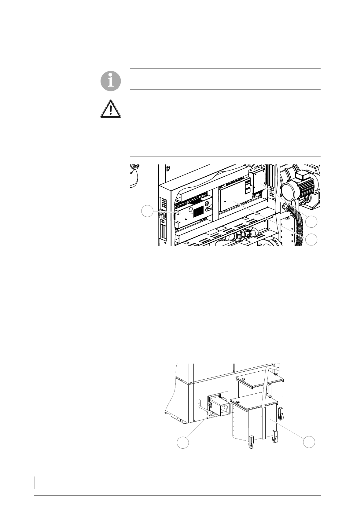
4 Planning and installation – Installing the heating system
WIRING THE MODULES
1
2
3
1
2
Depending on the hydraulic application, an EM 4 expansion
module may have to be used.
Important!
If the EM4 expansion module is used, this must be installed on the
rear next to the drive module. If expansion module EM8 or EM8+4 is
used instead or in addition it must be installed external boiler.
✎ For connecting the expansion module, refer to the “Electrical
plans HDG Compact 25 - 80”.
Figure 4/64 - Central module, drive module and EM4 extension module
1. Connect all plugs on the central unit (1) and drive module (3) and,
if necessary, the expansion module(s) in accordance with the circuit diagram.
✎ See “Electrical plans HDG Compact 25 - 80”.
2. Connect all cable channels (2).
✓ The modules are wired up.
INSTALLING AND ADJUSTING THE ASH CONTAINERS
1. Remove the ash containers from the packaging.
Figure 4/65 - Attaching the ash containers
2. Lift up the clamp handle (1).
72
Page 73
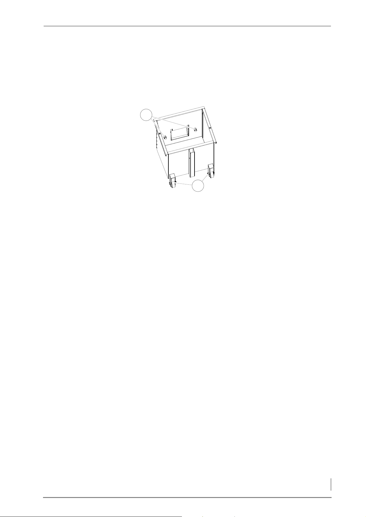
4 Planning and installation – Installing the heating system
3. Push the ash container (2) on to the ash removal pipe.
1
2
4. Press the clamp handle (1) downwards.
✓ Hold the clamp handle and press the ash container against the
seal of the ash removal door.
5. If the handles do not clamp, adjust them as follows.
6. Remove the cover from the
ash container.
7. Release the M10 cap nuts (size
17) (1) in the ash container.
8. Adjust ash containers with
the M10 nuts (size 17) under
the cap nuts (1) until the
clamp handles latch firmly.
Figure 4/66 - Adjusting the ash containers
9. Screw on the M10 nuts (size 17) and check that the clamp handles
clamp firmly.
✓ Grasp the clamp handles and seal the ash containers solidly on the
ash removal door.
10.Lock the M10 nuts (size 17) with the M10 cap nuts (size 17).
11.Close the ash containers in the reverse sequence.
12.If required, adjust the height of the wheels (2) so that they are
flush with the floor.
✓ The ash containers are mounted and adjusted.
CONNECTING THE CHIMNEY
✎ See section “4.3 Connections” in this chapter.
1. Connect the flue gas pipe to the chimney connection.
2. Make sure that the connecting piece does not protrude into the
chimney.
3. Seal the connection to the chimney with highly fireproof silicone
or with a suitable mortar.
✓ The boiler is now connected to the chimney.
73
Page 74
4 Planning and installation – Delivery system
4.6 Delivery system
The description for planning, installation and operation of the delivery system can be found in the corresponding operating manual.
✎ See the operating manual “Delivery system”.
4.7 Electrical system
The electrical connections must be made in accordance with DIN IEC
60364 “Setting up low-voltage electrical installations”.
✎ The technical details are described in the chapter “3 Mode of op-
eration”, section “3.3 Technical data”.
The modules must be connected in accordance with the circuit diagram.
✎ See “Electrical plans HDG Compact 25 - 80”.
4.8 Water
Important!
The heating system must be filled with water in accordance with
VDI guideline 2035, “Avoiding damage in hot water heating systems”.
The diaphragm expansion vessel must be constructed in accordance
with DIN EN 13831 “Closed expansion vessels with built-in diaphragm for integration in water installations”.
Before putting the system into operation, the pressure of the diaphragm expansion vessel must be adjusted for the conditions in the
heating system and in the building.
After putting the system into operation, heat up the system to the
maximum boiler temperature and bleed air from the system again to
make sure that there are no air pockets.
The safety devices must be implemented in accordance with DIN EN
12828 “Heating systems in buildings” and the correspondingly harmonised national standard DIN 4751, Part 2 “Closed, thermostatically
safeguarded heat generating systems with supply temperatures of
up to 120°C; safety equipment”.
In Germany, the requirements of the German energy conservation
ordinance (EnEV) must be met.
74
Page 75
4 Planning and installation – Thermal safety device
4.9 Thermal safety device
In accordance with DIN EN 12828, heating systems must be
equipped with safety devices to prevent the maximum operating
temperature from being exceeded. The safety heat exchanger serves
to protect the boiler against overheating and may not be used for
other purposes (i.e. as a regular heat exchanger). If the heat transfer
capacity is suddenly lost (for example, if the circulation pump for
raising the return temperature fails), heat production cannot be
stopped as quickly as with an oil- or gas-fired boiler. When the maximum operating temperature is exceeded, the thermal safety device
(TAS) is triggered and cold water flows through the safety heat exchanger. The excess energy generated is thus dissipated by this
“emergency cooling”. (This is an alternative to fast regulation.)
However, the safety heat exchanger and thermal safety device can
only serve their purpose if the following requirements have been
met:
• A flow pressure of at least two bar and a flow rate of 1800 l/h must
be available at the cold water inlet of the safety heat exchanger.
Mains-dependent, stand-alone supply systems are not safe enough
due to dependence upon the power supply!
• The distance between the supply and return lines of the thermal
safety device and the safety heat exchanger should not be less
than their nominal width. The supply line may not be equipped
with a shut-off valve.
• Water must be able to flow freely through the system.
• The flow pressure at the flue pipe connection on the boiler may
not significantly exceed the prescribed value.
The thermal safety device is to be inspected annually by an authorised, qualified technician to verify that it is functional.
The thermal safety device must be installed according to guidelines
from HDG Bavaria.
Important!
In order to prevent leaks, avoid turning the connections of the
safety heat exchanger anticlockwise when installing the thermal
safety device.
75
Page 76
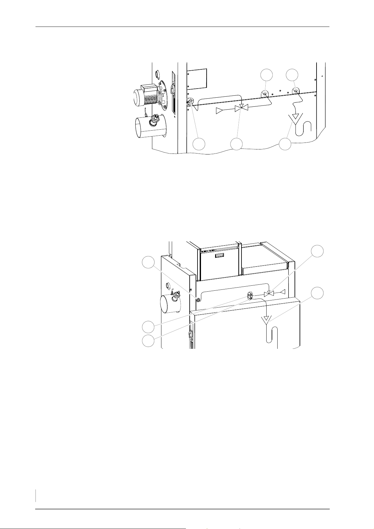
4 Planning and installation – Thermal safety device
HDG COMPACT 25/35
1 2 3
45
2
1
3
4
5
HDG C
OMPACT 45/50/65/80
Figure 4/67 - Installing the thermal safety device HDG Compact 25/35
1 Connection of immersion sensor for thermal safety device (DN 15,
inside thread)
2 Thermal safety device (TAS)
3 Tundish connection to drainage system
4 Safety heat exchanger outlet (DN 15 male)
5 Safety heat exchanger inlet (DN 15 male)
76
Figure 4/68 - Installing the thermal safety device (HDG Compact 45/50/65/80)
1 Connection of immersion sensor for thermal safety device (DN 15,
inside thread)
2 Safety heat exchanger inlet (DN 15 outside thread)
3 Safety heat exchanger outlet (DN 15 male)
4 Thermal safety device (TAS)
5 Tundish connection to drainage system
Page 77
5 Commissioning the system – Requirements
5 Commissioning the system
The heating system will initially be commissioned by specialists from
HDG Bavaria GmbH or an authorised HDG partner.
The commissioning includes an introduction to the operation and
maintenance of the heating system as well as performing measure-
ments on the system to determine exhaust emissions and firing per-
formance.
Danger!
Material damage and injury due to incorrect commissioning
Commissioning the system requires comprehensive expertise. If
this commissioning is done by an untrained person, the heating
system could be damaged.
Only allow authorised specialists to perform the commissioning.
5.1 Requirements
The following requirements must be met to ensure that no problems
occur during commissioning.
ENERAL INFORMATION • The boiler is installed properly.
G
• The feeding system and the delivery system are installed properly.
• The heating system has been filled with water as specified.
• The heating system has been bled.
• The pressure of the membrane expansion vessel has been
adapted to on-site conditions.
• All required DIN EN 12828 safety devices have been installed and
are ready for operation.
• The power supply to all components is ensured. (Makeshift solu-
tions are not sufficient!)
• All doors and openings on the boiler and on the chimney connec-
tion pipe have been checked for a proper seal.
• Air supply for combustion has been provided.
• A sufficient amount of fuel is available.
77
Page 78
5 Commissioning the system – Procedure
ELECTRICAL CONNECTIONS
5.2 Procedure
Danger!
Dangerous electrical current or voltage
Isolate the mains cable to the heating system.
• All the sensors and actuators are correctly connected and properly
plugged in to the module.
• The mains supply is correctly connected.
• The cables between the control unit, central module and drive
module or to the expansion modules are attached properly.
• Any unused inputs are bypassed.
Important!
Commission the HDG Compact 25 - 80 heating system in accordance with the specifications from the supplied commissioning protocol.
✎ See also operating manual “HDG Control”, Chapter “4 Commis-
sioning the system”.
Caution!
Damage from smoke
If the ash necks are empty or the ash containers are not at least half-
filled when commissioning or re-starting after cleaning, there is a
danger of smoke coming from the boiler.
Make sure that both ash containers or the ash necks are at least halffilled with ash or sand.
78
Page 79

6 Using the heating system – Control unit HDG Control
6 Using the heating system
6.1 Control unit HDG Control
✎ You can find all information and instructions for setting up and
operating the boiler and weather-compensated heating control
HDG Control in the operating manual “HDG Control”.
6.2 Filling the fuel storage room
REQUIREMENTS
The following requirements must be met before the fuel storage can
be filled:
• The fuel storage has been initially approved by an authorised spe-
cialist.
• The fuel storage is dry and free of any foreign bodies.
• The requirements of government safety organisations must be
met.
PROCEDURE FOR FILLING WITH WOOD CHIPS
1. Switch the heating system on.
✎ See the “HDG Control” operating manual, chapter “5 Using the
control unit”, section “5.2 Switching on the heating system”.
2. Manually run the delivery system for 30 seconds or until the arms
are folded into the dome at the start of the filling process.
Warning!
Damage to delivery system during filling
If the heating system is not switched on during filling of the fuel
storage, the overload protection of the delivery system could be
triggered when the heating system is switched on after the filling.
When filling the fuel storage for the first time, activate the delivery
system by switching in manual operation. Check each time when
filling that the heating system is running in automatic mode.
3. Fill the fuel storage room.
✓ The filling of the fuel storage is completed.
79
Page 80
6 Using the heating system – Performing a chimney sweep measurement
PROCEDURE FOR FILLING WITH PELLETS
1. Switch the heating system off.
✎ See the “HDG Control” operating manual, chapter “5 Using the
control unit”, section “5.3 Switching off the heating system”.
✓ The heating system is now switched off.
2. Double check that the heating system is switched off and wait for
burn out to finish.
3. Inform the tanker driver that the pellet storage room can be filled.
4. After filling is completed, close the injection and extraction noz-
zles.
5. Re-starting the heating system.
✎ See the “HDG Control” operating manual, chapter “5 Using the
control unit”, section “5.2 Switching on the heating system”.
✓ The filling of the pellet storage is completed.
6.3 Performing a chimney sweep measurement
✎ See the “HDG Control” operating manual, chapter “5 Using the
control unit”, section “5.8 Performing a chimney sweep measurement”.
6.4 Switching off the heating system for repair work
Important!
Frost danger
Only completely shut off the power to the heating system if the
danger of frost can be ruled out.
1. Switch the heating system off.
✎ See the “HDG Control” operating manual, chapter “5 Using the
control unit”, section “5.3 Switching off the heating system”.
2. Allow the fire in the boiler to burn out and cool off.
There is still electrical voltage in the system.
3. Turn off the main switch.
✓ The heating system is switched off and without current.
80
Page 81
7 Cleaning and servicing the heating system – Cleaning and servicing schedule
7 Cleaning and servicing the heating system
GENERAL INFORMATION To ensure fault-free and safe operation, certain cleaning and mainte-
nance work is necessary. This procedure will also help you avoid expensive repairs, provided you observe the recommended intervals.
The cleaning and maintenance work can also be performed by an authorised specialist heating company where a servicing contract has
been agreed.
S
PARE PARTS
Only use genuine HDG spare parts. You can obtain HDG spare parts
from your specialist heating company.
7.1 Cleaning and servicing schedule
The specified cleaning intervals are guidelines.
Depending on the quality of the fuel and the power used by the
heating system (more frequent on/off operation) the intervals may
vary.
Interval Component See page ...
Weekly / as required • Cleaning the tilting grate
• Checking and empty the ash container
• Lubricate the feeding system (150 operating
hours)
• Lubricate the heat exchanger cleaner (40 oper-
ating hours)
Every 6 months (approx. 900
operating hours)
Annually (approx. 1800 operating hours)
before every second filling • Checking the fuel storage 101
• Checking the drive chains
• Cleaning the cleaning shaft and turbulaters*
• Checking and cleaning the lambda sensor
• Cleaning the flue gas pipe
• Cleaning the ash removal system
• Cleaning the flue gas temperature sensor
• Cleaning the ignition fan
• Cleaning the flue gas fan
• Cleaning the pressure equalisation hose
• Checking and lubricating the fill level indicator
Table 7/1 - Cleaning and servicing schedule
*At least twice yearly; possibly more often depending on the quality of the fuel.
83
84
87
87
88
91
93
94
95
96
96
98
99
99
81
Page 82
7 Cleaning and servicing the heating system – Requirements
7.2 Requirements
GENERALLY APPLICABLE SAFETY INSTRUCTIONS
Please be sure to observe the following generally applicable safety
instructions when performing any cleaning or maintenance work:
Warning!
Danger of asphyxiation due to carbon monoxide
If the boiler is in operation, carbon monoxide can be emitted
through open doors, lids or other cleaning openings.
When performing cleaning and maintenance work, do not leave the
cleaning openings, doors and lids open any longer than necessary.
Caution!
Danger of burns from hot surfaces
During operation, the boiler surfaces under the cladding are hot.
Even when turned off, they only cool down slowly.
Switch the heating system off and only start with the cleaning and
maintenance work when the surfaces have cooled down.
OMBUSTION CHAMBER
C
TEMPERATURE SENSOR
Warning!
Risk of injury from automatically driven components
If the heating system is switched on, automatically driven compo-
nents can unexpectedly start running. Limbs or fingers could become caught and crushed.
Switch the heating system off before performing any cleaning or
maintenance work on automatically driven components.
Important!
When applying lubricants, oils and grease, observe the specifications of the respective manufacturer.
Caution!
Damage to the combustion chamber temperature sensor
The combustion chamber temperature sensor consists of a ceramic
part that can be damaged by mishandling.
Take care to ensure that the combustion chamber temperature
sensor is not damaged during cleaning and maintenance work.
82
Page 83
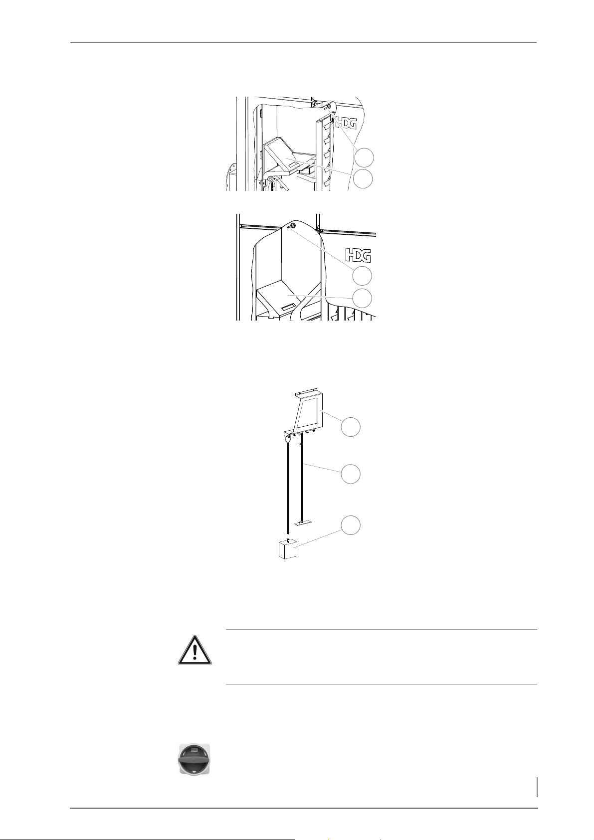
7 Cleaning and servicing the heating system – Requirements
1 Combustion chamber tem-
1
2
1
2
1
2
3
perature sensor
2 Secondary combustion
chamber
Figure 7/1 - HDG Compact 25/35 combustion chamber temperature sensor
1 Combustion chamber tem-
perature sensor
2 Secondary combustion
chamber
Figure 7/2 - HDG Compact 45/50/65/80 combustion chamber temperature sensor
CLEANING TOOLS
1 Wall holder
2Scraper
3Cleaning brush
Figure 7/3 - Cleaning tools
CLEANING THE TILTING GRATE
Important!
✎ Observe the “Generally applicable safety instructions” in this sec-
tion.
1. Switch the heating system off.
✎ See the “HDG Control” operating manual, chapter “5 Using the
control unit”, section “5.3 Switching off the heating system”.
2. Allow the fire in the heating system to burn out and cool down.
3. Turn the main switch off.
83
Page 84
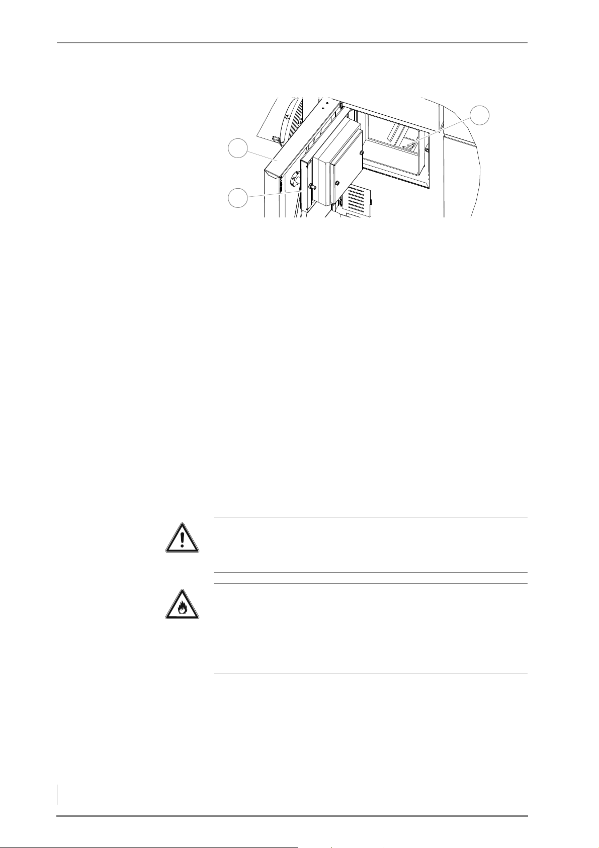
7 Cleaning and servicing the heating system – Requirements
Figure 7/4 - Cleaning the tilting grate
3
2
1
4. Open the front door (1) of the boiler.
5. Open the combustion chamber door (2).
6. Inspect the grate (3) for encrustations of cinder or foreign bodies.
7. Remove any encrustations with a suitable cleaning tools or empty
the grate in manual operation.
✎ See the “HDG Control” operating manual, chapter “6 Parameter
HDG Compact 25 - 80” section “6.2 Boiler” paragraph “Test”.
8. After cleaning, close the combustion chamber door (2) and the
front door (1) of the boiler.
9. Re-starting the heating system.
✎ See the “HDG Control” operating manual, chapter “5 Using the
control unit”, section “5.2 Switching on the heating system”.
✓ The tilting grate is cleaned.
CHECKING AND EMPTYING THE ASH CONTAINER
Important!
✎ Observe the “Generally applicable safety instructions” in this sec-
tion.
Caution!
Danger of fire from combustion residues
Hot combustion residues can lead to a fire.
Allow the ash to cool and place it only in a suitable fireproof con-
tainer.
84
Page 85
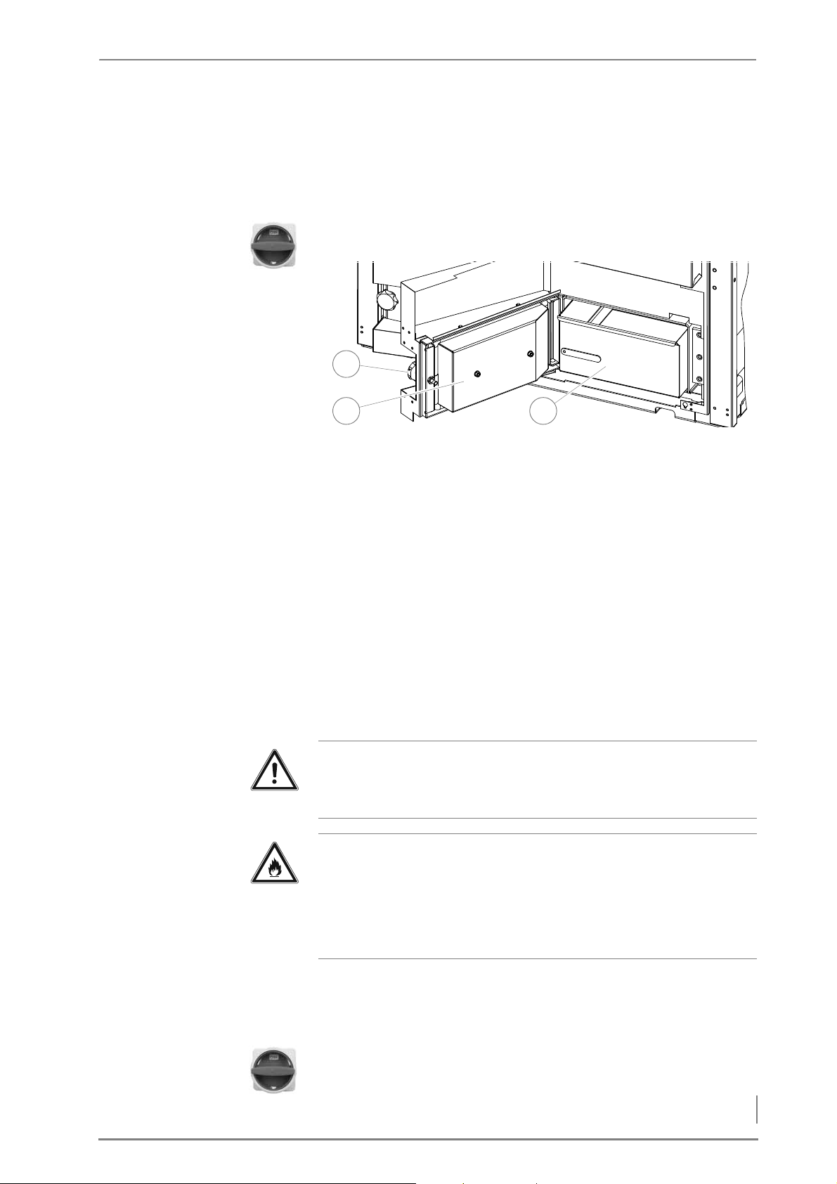
7 Cleaning and servicing the heating system – Requirements
CHECKING AND EMPTYING THE
32
1
ASH PAN (MANUAL ASH
REMOVAL)
1. Switch the heating system off.
✎ See the “HDG Control” operating manual, chapter “5 Using the
control unit”, section “5.3 Switching off the heating system”.
2. Allow the fire in the heating system to burn out and cool down.
3. Turn the main switch off.
Figure 7/5 - Check the ash pan and empty.
4. Unscrew the star-grip screws (1) and open the ash doors.
5. Pull out the ash pan (3).
6. Empty the ash into a fireproof container.
C
HECKING AND EMPTYING ASH
CONTAINERS (AUTOMATIC ASH
REMOVAL)
7. Reinsert the ash pan (3) and lock the ash doors (2) in the reverse
sequence.
8. Re-starting the heating system.
✎ See the “HDG Control” operating manual, chapter “5 Using the
control unit”, section “5.2 Switching on the heating system”.
✓ The ash pans have been checked and emptied.
Important!
✎ Observe the “Generally applicable safety instructions” in this sec-
tion.
Caution!
Danger of fire from combustion residues
Hot combustion residues can lead to a fire.
Allow the ash to cool and place it only in a suitable fireproof con-
tainer.
1. Switch the heating system off.
✓ See the “HDG Control” operating manual, chapter “5 Using the
control unit”, section “5.3 Switching off the heating system”.
2. Allow the fire in the heating system to burn out and cool down.
3. Turn the main switch off.
85
Page 86
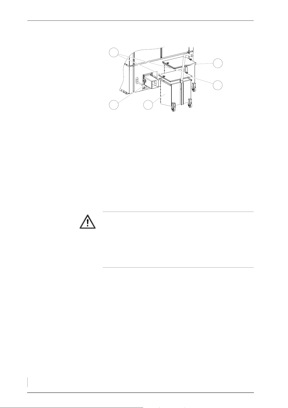
7 Cleaning and servicing the heating system – Requirements
Figure 7/6 - Checking and empty the ash container
32
5
1
4
4. Release the star-grip screws (1).
5. Lift up the lid (4) and remove it.
6. Check the fill level of the ash containers (3).
7. If the ash containers (3) are full, empty them.
8. Fasten the transport handle (5) on the ash container (3).
9. Lift up the clamp handle (2) and release the ash container (3).
10.Pull the ash container (3) forward out of the ash channel of the ash
removal system.
11.Empty the ash into a fireproof container.
12.If the ash containers (3) are not yet full, reclose them.
Caution!
Damage from smoke
If the ash necks are empty or the ash containers are not at least half-
filled when commissioning or re-starting after cleaning, there is a
danger of smoke coming from the boiler.
Make sure that both ash containers or the ash necks are at least halffilled with ash or sand.
13.Mount the lid (4) on the ash container (3) and install the ash con-
tainer (3) in the boiler in the reverse sequence.
14.Repeat the process for the second ash container.
✎ See the “HDG Control” operating manual, chapter “5 Using the
control unit”, section “5.2 Switching on the heating system”.
✓ Inspection and emptying of the ash containers has been com-
pleted.
86
Page 87
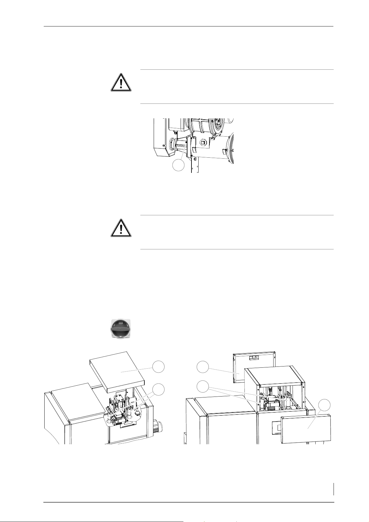
7 Cleaning and servicing the heating system – Requirements
LUBRICATING THE FEEDING SYSTEM
1
4
3
5
1
2
HDG Compact 25/35
HDG Compact 45/50/65/80
Important!
✎ Observe the “Generally applicable safety instructions” in this sec-
tion.
The feeding system must be lubricated every 150 operating hours.
1. Place the grease gun on the
lubricating nipple (1).
2. Press three strokes of grease
into the feeding system.
✓ The feeding system is lubri-
cated.
Figure 7/7 - Lubricating the feeding system
LUBRICATE HEAT EXCHANGER CLEANING
Important!
✎ Observe the “Generally applicable safety instructions” in this sec-
tion.
The heat exchanger cleaner must be lubricated every 40 operating
hours.
1. Switch the heating system off.
✎ See the “HDG Control” operating manual, chapter “5 Using the
control unit”, section “5.3 Switching off the heating system”.
2. Allow the fire in the heating system to burn out and cool down.
3. Turn the main switch off.
Figure 7/8 - Lubricate heat exchanger cleaning
4. Remove the top cover(1) or the front (5) and the rear (3) covers of
the heat exchanger cleaner.
87
Page 88
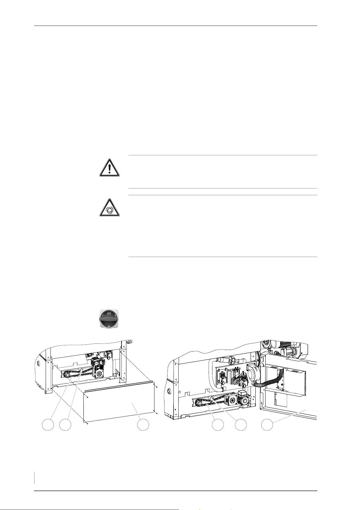
7 Cleaning and servicing the heating system – Requirements
5. Clean the running surfaces of the shafts (2 + 4) and spray them
4 5 6
HDG Compact 25/
HDG Compact 45/50/65/80
31 2
with heat-resistant grease.
6. Install the covers (1 or 3 + 5) in the reverse sequence.
7. Re-starting the heating system.
✎ See the “HDG Control” operating manual, chapter “5 Using the
control unit”, section “5.2 Switching on the heating system”.
✓ The heat exchanger cleaner is now lubricated.
CHECKING THE DRIVE CHAINS
Important!
✎ Observe the “Generally applicable safety instructions” in this sec-
tion.
Warning!
Risk of injury from automatically driven components
When the heating system is switched on, the gears and drive chains
that move the various augers rotate. Fingers could be crushed
during cleaning and servicing work.
CHECKING THE DRIVE CHAINS OF
THE ASH REMOVAL
SYSTEM
Switch off the heating system before checking the drive chains.
1. Switch the heating system off.
✓ See the “HDG Control” operating manual, chapter “5 Using the
control unit”, section “5.3 Switching off the heating system”.
2. Allow the fire in the heating system to burn out and cool down.
3. Turn the main switch off.
Figure 7/9 - Checking the drive chain of the ash removal system
4. Remove the lower rear cladding (3 or 6) from the boiler.
88
Page 89
7 Cleaning and servicing the heating system – Requirements
C
HECKING THE DRIVE CHAIN OF
THE FEEDING SYSTEM
5. Check the chain tension (1 or 4).
✓ If the drive chain has approximately 1 cm play, the tension is cor-
rect.
✓ If the drive chain has more play, it must be tightened.
6. Loosen the M10 locking nut (SW17) on the chain tensioner (2 or 5).
✓ The chain tensioner can be moved.
7. Move the chain tensioner (2 or 5) downwards until the drive chain
has sufficient tension again.
8. Secure the chain tensioner (2 or 5) in this position.
9. Replace the lower cladding of the boiler.
10.Re-starting the heating system.
✎ See the “HDG Control” operating manual, chapter “5 Using the
control unit”, section “5.2 Switching on the heating system”.
✓ The check of the drive chain of the ash removal system is com-
pleted.
Important!
✎ Observe the “Generally applicable safety instructions” in this sec-
tion.
Warning!
Risk of injury from automatically driven components
When the heating system is switched on, the gears and drive chains
that move the various augers rotate. Fingers could be crushed
during cleaning and servicing work.
Switch the heating system off before checking the drive chains.
1. Switch the heating system off.
✓ See the “HDG Control” operating manual, chapter “5 Using the
control unit”, section “5.3 Switching off the heating system”.
2. Allow the fire in the heating system to burn out and cool down.
3. Turn the main switch off.
89
Page 90
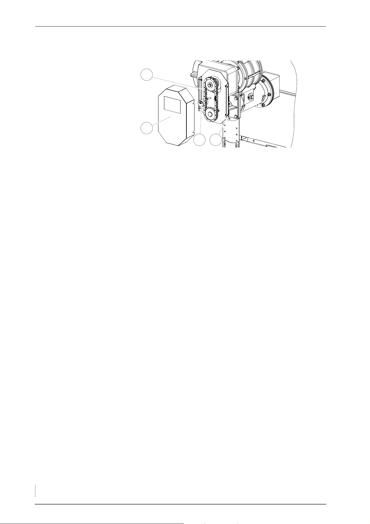
7 Cleaning and servicing the heating system – Requirements
Figure 7/10 - Checking the feeding system drive chain
3
1
2
4
4. Release the M6 screws (SW10) (4) of the chain guard cover (2) and
remove it.
5. Check the chain tension (1).
✓ If the drive chain has approximately 1 cm play, the tension is cor-
rect.
✓ If the drive chain has more play, it must be tightened.
6. Loosen the M10 locking nut (SW17) on the chain tensioner (3).
✓ The chain tensioner can be moved.
7. Move the chain tensioner (3) to the side until the drive chain has
sufficient tension again.
8. Secure the chain tensioner (3) in this position.
✓ The drive chain is tightened.
9. Mount the chain guard (2) back on the feeding system.
10.Re-starting the heating system.
✎ See the “HDG Control” operating manual, chapter “5 Using the
control unit”, section “5.2 Switching on the heating system”.
✓ Checking the feeding drive chain is completed.
90
Page 91
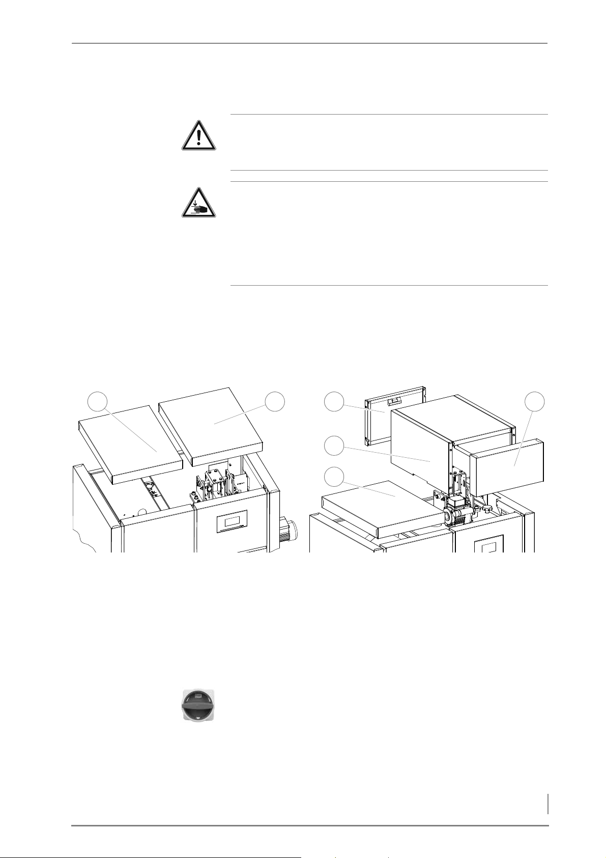
7 Cleaning and servicing the heating system – Requirements
CLEANING THE CLEANING SHAFT AND TURBULATORS
4
3 621
HDG Compact 25/35
HDG Compact 45/50/65/80
5
Important!
✎ Observe the “Generally applicable safety instructions” in this sec-
tion.
Warning!
Danger of injury
The cleaning shaft lid is very heavy and can fall shut. Hands and
arms could thereby be crushed.
Take care not to bump into the opened cleaning shaft lid and cause
it to fall shut.
1. Switch the heating system off.
✎ See the “HDG Control” operating manual, chapter “5 Using the
control unit”, section “5.3 Switching off the heating system”.
2. Allow the fire to burn out and cool down.
Figure 7/11 - Removing hoods
3. Remove the top cover (1 or 5) on the feed side.
4. Remove the top cover (2) or the rear and front top panels (3+6).
5. Remove the cover (4) of the heat exchanger cleaner.
6. In manual mode move the turbulators to the lowest position.
✎ See the “HDG Control” operating manual, chapter “6 Parameter
HDG Compact 25 - 80” section “6.2 Boiler” paragraph “Test”.
7. Turn the main switch off.
91
Page 92
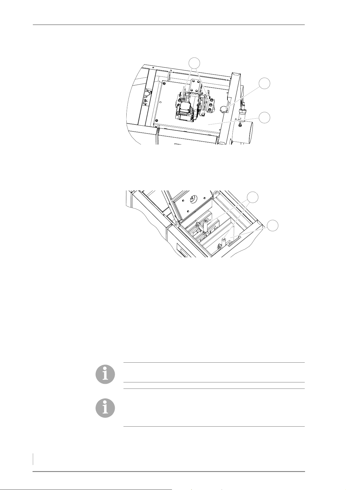
7 Cleaning and servicing the heating system – Requirements
Figure 7/12 - Folding out the cleaning shaft lid
1
3
2
1
2
8. Release the star-grip screw (2).
9. Release the two middle M12 hexagon socket screws (SW10) (1).
10.Open the cleaning shaft lid (3).
Figure 7/13 - Pulling out the turbulators
11.Pull out the turbulators on the crossbar shafts (1) in an upward di-
rection.
12.Visually inspect the cleaning turbulators for encrustations and re-
move with a suitable tool.
13.Brush off the heat exchanger surfaces (2) with a suitable tool
(e.g.cleaning brush, included in delivery).
14.Clean the crossbar shafts (1) and spray them with heat-resistant
grease.
15.Reassemble the heat exchanger cleaner and the cleaning shaft lid
in the reverse sequence.
For easier assembly, align the push rods of the turbulators with the
centre of the heat exchanger.
Ensure that the heat exchanger cleaning motor cable does not get
pinched when closing the cleaning shaft lid.
Tighten the two hexagon socket screws of the cleaning shaft lid.
Then turn the screws a quarter-turn back in the opposite direction.
16.Replace the covers.
17.Re-starting the heating system.
92
Page 93
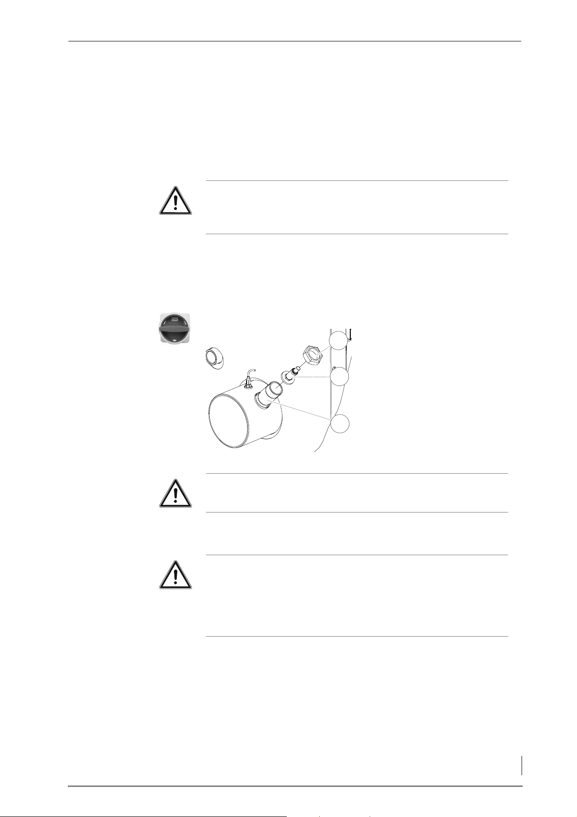
7 Cleaning and servicing the heating system – Requirements
✎ See the “HDG Control” operating manual, chapter “5 Using the
1
2
3
control unit”, section “5.2 Switching on the heating system”.
✓ The cleaning shaft and the turbulators have now been cleaned.
CHECKING AND CLEANING THE LAMBDA SENSOR
Important!
✎ Observe the “Generally applicable safety instructions” in this sec-
tion.
1. Switch the heating system off.
✎ See the “HDG Control” operating manual, chapter “5 Using the
control unit”, section “5.3 Switching off the heating system”.
2. Allow the fire to burn out and cool down.
3. Turn the main switch off.
4. Using a pipe wrench, unscrew
the DN 40 union nut (1).
5. Remove the lambda sensor
(2) and the ceramic washer
under it from the connection
nipple (3) of the flue gas pipe.
Figure 7/14 - Cleaning the lambda sensor
Important!
Steel bristles will damage the lambda sensor.
6. Clean the lambda sensor (2) with a vacuum cleaner.
7. Clean out any deposits inside the connection nozzle (3).
Important!
When reinstalling the lambda sensor, make sure its seal is intact.
Use a pipe wrench to tighten the union nut. Do not tighten the
lambda sensor excessively. Never tighten the lambda sensor by the
body of the sensor.
8. Reinstall the lambda sensor (2) in the reverse sequence.
9. Check the lambda sensor (2) for a secure fit.
10.Carefully tighten the lambda sensor (2) in the ceramic seal with a
22 mm spanner.
11.Re-starting the heating system.
✎ See the “HDG Control” operating manual, chapter “5 Using the
control unit”, section “5.2 Switching on the heating system”.
✓ The lambda sensor has been checked and cleaned.
93
Page 94
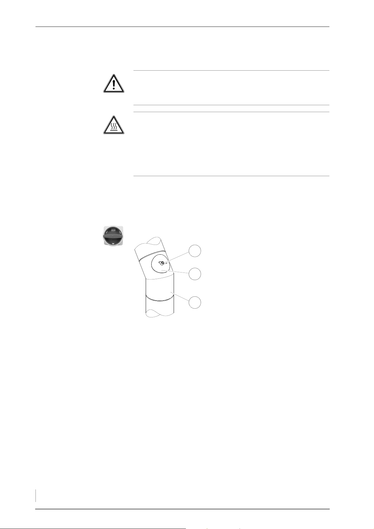
7 Cleaning and servicing the heating system – Requirements
CLEANING THE FLUE GAS PIPE
1
2
3
Important!
✎ Observe the “Generally applicable safety instructions” in this sec-
tion.
Caution!
Danger of burns from hot surfaces
The surface of the flue pipe becomes very hot during operation.
Even when turned off, it only cools down slowly.
Switch the heating system off and only start with the cleaning and
maintenance work when the surfaces have cooled down.
1. Switch the heating system off.
✓ See the “HDG Control” operating manual, chapter “5 Using the
control unit”, section “5.3 Switching off the heating system”.
2. Allow the fire to burn out and cool down.
3. Turn the main switch off.
4. Unscrew the wing nut (1) on
the inspection hatch lid (2).
5. Remove the inspection hatch
lid (2) from the flue gas pipe
(3).
6. Check whether the flue gas
pipe (3) needs cleaning.
7. If necessary, suction the ash
from the flue gas pipe using a
vacuum cleaner (3).
Figure 7/15 - Cleaning the flue gas pipe
8. Fasten the inspection hatch cover firmly on the flue pipe with the
wing nut.
9. Re-starting the heating system.
✎ See the “HDG Control” operating manual, chapter “5 Using the
control unit”, section “5.2 Switching on the heating system”.
✓ The cleaning of the flue gas pipe is completed.
94
Page 95
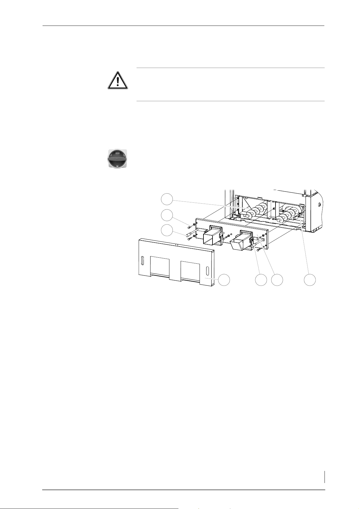
7 Cleaning and servicing the heating system – Requirements
CLEANING THE ASH REMOVAL SYSTEM
1
754 6
2
3
Important!
✎ Observe the “Generally applicable safety instructions” in this sec-
tion.
1. Switch the heating system off.
✓ See the “HDG Control” operating manual, chapter “5 Using the
control unit”, section “5.3 Switching off the heating system”.
2. Allow the fire to burn out and cool down.
3. Turn the main switch off.
4. Remove both ash containers.
✓ See section “Checking and emptying the ash container” in this
chapter.
Figure 7/16 - Checking and cleaning the ash removal system
5. Set the two ash container clamp handles (3+5) in the horizontal
position.
6. Remove the cover of the ash removal door (4).
7. Undo the five fastening screws (SW19) (2).
8. Pull the ash removal door (6) forward off the ash removal augers.
9. Check the combustion chamber ash compartment (1) and the
heat exchanger ash compartment (7) for foreign bodies, encrustations or clumps of ash and remove these if necessary using a
cleaning tools (e.g. a scraper as included in delivery).
10.Mount the components in the reverse sequence.
11.Re-starting the heating system.
✎ See the “HDG Control” operating manual, chapter “5 Using the
control unit”, section “5.2 Switching on the heating system”.
✓ The ash removal system is now clean.
95
Page 96
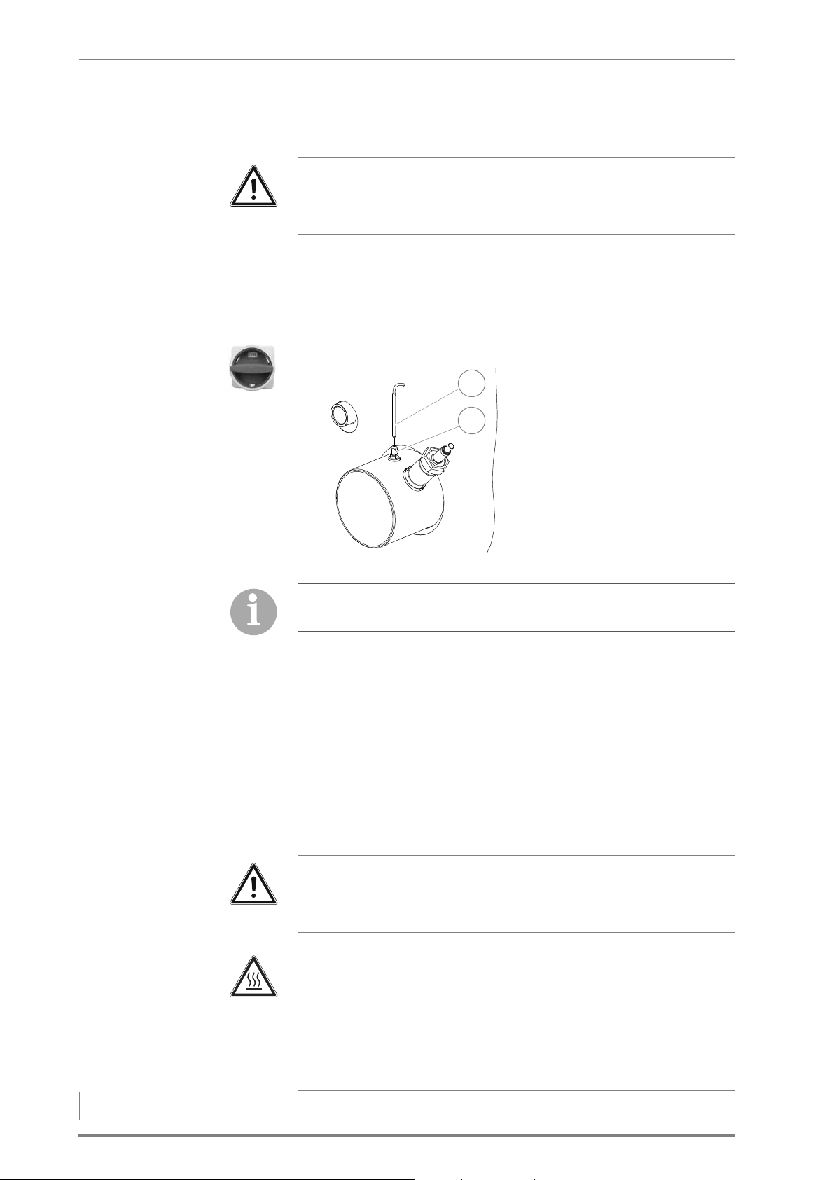
7 Cleaning and servicing the heating system – Requirements
CLEANING THE FLUE GAS TEMPERATURE SENSOR
1
2
Important!
✎ Observe the “Generally applicable safety instructions” in this sec-
tion.
1. Switch the heating system off.
✓ See the “HDG Control” operating manual, chapter “5 Using the
control unit”, section “5.3 Switching off the heating system”.
2. Allow the fire to burn out and cool down.
3. Turn the main switch off.
4. Loosen the M10 clamp nut
(size 17) (2) and pull the flue
gas temperature sensor (1)
out of the sensor clamp assembly (2).
5. Clean the sensor surface with
a moist cloth.
Figure 7/17 - Cleaning the flue gas temperature sensor
The flue gas temperature sensor must be installed so that the
sensor projects approx. 2 cm out of the clamp screw.
6. Mount the flue gas temperature sensor (1) in the reverse se-
quence.
7. Re-starting the heating system.
✎ See the “HDG Control” operating manual, chapter “5 Using the
control unit”, section “5.2 Switching on the heating system”.
✓ The flue gas temperature sensor has been cleaned.
CLEANING THE IGNITION FAN
Important!
✎ Observe the “Generally applicable safety instructions” in this sec-
tion.
Caution!
Danger of burns from hot surfaces
The hot air nozzle of the ignition fan becomes very hot during oper-
ation. Even when turned off, it only cools down slowly.
Switch the heating system off and only start with the cleaning and
maintenance work once the hot air nozzle has cooled down.
96
Page 97
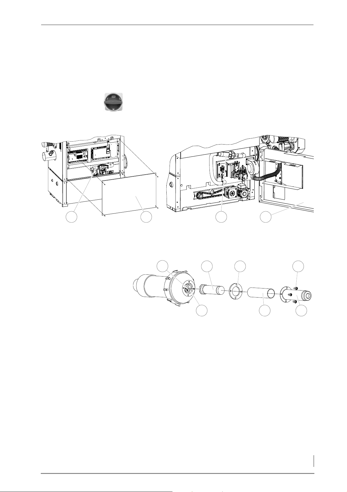
7 Cleaning and servicing the heating system – Requirements
1. Switch the heating system off.
3 4
HDG Compact 25/35
HDG Compact 45/50/65/80
21
1
6 5
432
7
✎ See the “HDG Control” operating manual, chapter “5 Using the
control unit”, section “5.3 Switching off the heating system”.
2. Allow the fire to burn out and cool down.
3. Turn the main switch off.
Figure 7/18 - Dismantling the ignition fan
4. Remove the middle (2) or lower (4) rear cladding from the boiler.
5. Pull the ignition fan (1 or 3) out of the retainer.
Figure 7/19 - Checking and cleaning the ignition fan
6. Unscrew the four M4 stainless steel slotted screws (4) of the hot air
nozzle (5).
7. Pull off the hot air nozzle (5).
8. Remove the insulating tube (6) and the seal (3).
9. Pull the heating element (2) out of the plug contacts (7).
10.Check the heating element (2) for dirt.
11.Remove any dirt by blowing it off.
12.Check the photocell (1) for dirt.
13.Remove any dirt using a cotton swab.
14.Reinstall the ignition fan into the heating system in the reverse se-
quence.
15.Re-starting the heating system.
97
Page 98
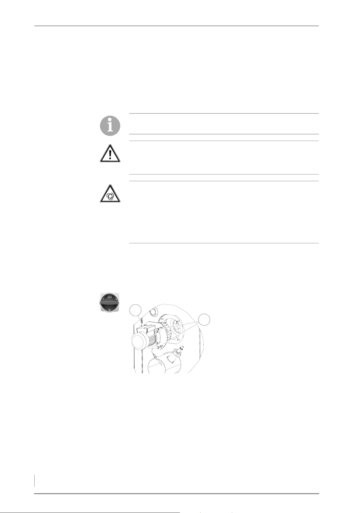
7 Cleaning and servicing the heating system – Requirements
✎ See the “HDG Control” operating manual, chapter “5 Using the
2
1
control unit”, section “5.2 Switching on the heating system”.
✓ The cleaning of the ignition fan is completed.
CLEANING THE FLUE GAS FAN
The flue gas fan is only available with the HDG Compact 25/35
boiler.
Important!
✎ Observe the “Generally applicable safety instructions” in this sec-
tion.
Warning!
Risk of injury from automatically driven components
When working on the flue gas fan, unexpected start-up of the fan
wheel poses the danger of hand injuries.
Switch the heating system off before performing any cleaning or
maintenance work on the flue gas fan.
1. Switch the heating system off.
✎ See the “HDG Control” operating manual, chapter “5 Using the
control unit”, section “5.3 Switching off the heating system”.
2. Allow the fire to burn out and cool down.
3. Turn the main switch off.
4. Pull the plug of the flue gas
fan cable out of the plug
board.
5. Remove the four M8 cap nuts
(2) with a 13 mm spanner.
6. Pull the flue gas fan (1) out to-
ward the back to remove it.
Figure 7/20 - Cleaning the flue gas fan
7. Check whether the flue gas fan (1) is dirty and clean it with a steel
brush if needed.
8. Mount the flue gas fan in the reverse sequence.
9. Re-starting the heating system.
✎ See the “HDG Control” operating manual, chapter “5 Using the
control unit”, section “5.2 Switching on the heating system”.
✓ The flue gas fan has been cleaned.
98
Page 99
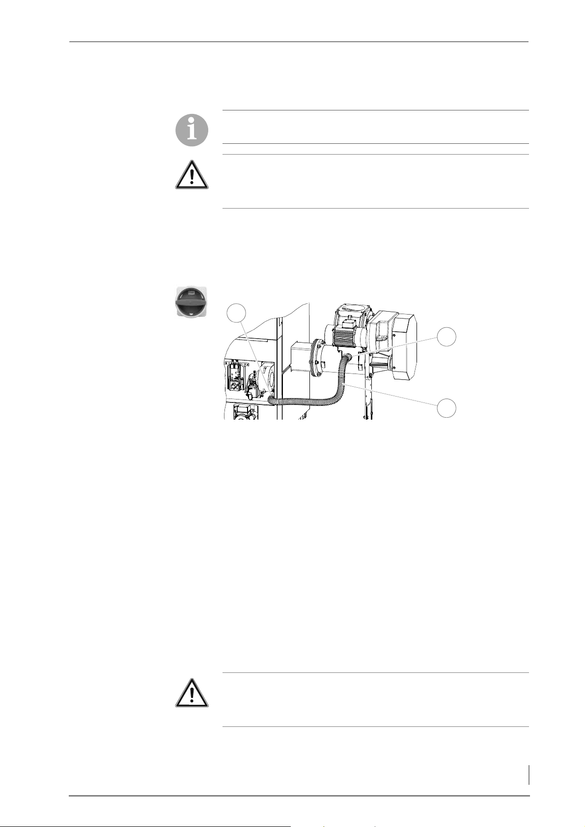
7 Cleaning and servicing the heating system – Requirements
CLEANING THE PRESSURE EQUALISATION HOSE
1
2
3
The pressure equalisation hose is only available with the
HDG Compact 45/50/65/80 boiler.
Important!
✎ Observe the “Generally applicable safety instructions” in this sec-
tion.
1. Switch the heating system off.
✓ See the “HDG Control” operating manual, chapter “5 Using the
control unit”, section “5.3 Switching off the heating system”.
2. Allow the fire to burn out and cool down.
3. Turn the main switch off.
Figure 7/21 - Cleaning the pressure equalisation hose
4. Use a pipe wrench to release the DN 40 union nuts on the feed
system connection nozzle (2) and on the boiler connection nozzle
(1).
5. Detach the pressure equalisation hose (3).
6. Inspect the pressure equalisation hose (3) for dirt and dislodge it if
necessary by forceful shaking and careful bending.
7. Mount the pressure equalisation hose in the reverse sequence.
8. Re-starting the heating system.
✎ See the “HDG Control” operating manual, chapter “5 Using the
control unit”, section “5.2 Switching on the heating system”.
✓ The pressure equalisation hose is cleaned.
CLEANING AND LUBRICATING THE OVERFILL LEVER
Important!
✎ Observe the “Generally applicable safety instructions” in this sec-
tion.
1. Switch the heating system off.
99
Page 100
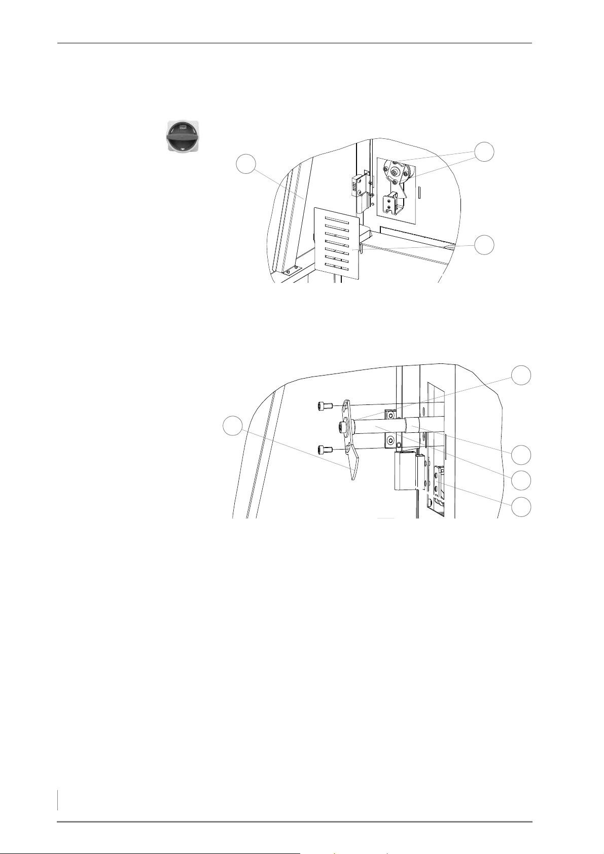
7 Cleaning and servicing the heating system – Requirements
✓ See the “HDG Control” operating manual, chapter “5 Using the
3
1
2
3
1
2
4
5
control unit”, section “5.3 Switching off the heating system”.
2. Turn the main switch off.
Figure 7/22 - Dismantling the level indicator
3. Open the front door (1).
4. Take off the cover plate (3) off the over fill lever.
5. Release the upper and lower M6 hexagon socket screws (SW5)(2).
Figure 7/23 - Dismantling the level indicator
6. Turn the switch plate (1) with the mounted fill level indicator to
the left and carefully pull it forward as far as it will go.
7. Clean the running surfaces (2 + 3) and the shaft (4) of the level in-
dicator.
8. Lubricate the running surfaces (2 + 3) of the level indicator with
heat-resistant grease.
9. Mount the fill level indicator in the reverse sequence.
10.Afterwards, check that the distance of the fill level indicator limit
switch (5) to the switch plate (1) is maximally 3 mm. If the contact
is correct, an LED lights up on the limit switch.
11.Re-starting the heating system.
✎ See the “HDG Control” operating manual, chapter “5 Using the
control unit”, section “5.2 Switching on the heating system”.
✓ The cleaning and lubricating of the fill level indicator is com-
pleted.
100
 Loading...