

Page 1
IS311SX-00A
Your Hayward Pro Series high-rate sand filter is a high
performance, totally corrosion-proof filter that blends superior
flow characteristics and features with ease of operation. It
represents the very latest in high-rate sand filter technology.
It is virtually foolproof in design and operation and when
installed, operated and maintained according to instructions,
your filter will produce clear, sparkling water with only the
least attention and care.
HOW IT WORKS
Your filter uses special filter sand to remove dirt particles
from the water. Filter sand is loaded into the filter tank and
functions as the permanent dirt removing media. The pool
water, which contains suspended dirt particles, is pumped
through your piping system and is automatically directed by
the patented filter control valve to the top of the filter tank.
As the pool water is pumped through the filter sand, dirt
particles are trapped by the sand bed, and filtered out. The
cleaned pool water is returned from the bottom of the filter
tank, through the control valve and back to the pool through
the piping system. This entire sequence is continuous and
automatic and provides for total recirculation of pool water
through your filter and piping system.
After a period of time, the accumulated dirt in the filter causes
a resistance to flow, and the flow diminishes. This means it
is time to clean (backwash) your filter. With the control valve
in the backwash position, the water flow is automatically
reversed through the filter so that it is directed to the bottom
of the tank, up through the sand, flushing the previously
trapped dirt and debris out the waste line. Once the filter is
backwashed (cleaned) of dirt, the control valve is manually
resequenced to Rinse (Vari-Flo Control Valve only), and
then Filter, to resume normal filtering.
INSTALLATION
Only simple tools (screwdriver and wrenches), plus pipe
sealant for plastic adapters, are required to install and/or
service the filter.
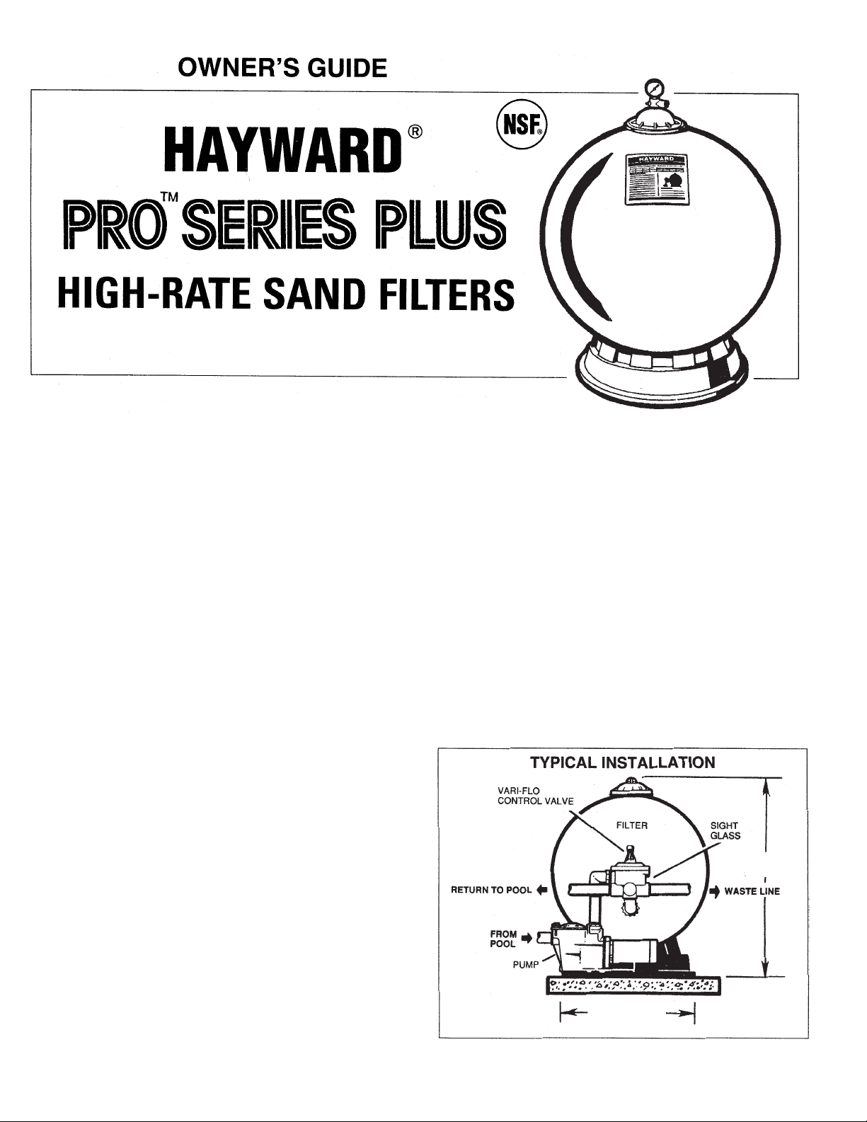
The filter system should be installed, not more than 6
feet above pool water level, on a level concrete slab,
very firm ground, or equivalent, as recommended by
your pool dealer. Position the filter so that the piping
connections, control valve and winter drain are
convenient and accessible for operation, service and
winterizing.
Assemble filter control valve to filter. Align the two (2)
valve pipe connections, with O-rings in place, with the
two openings in the side of the filter tank and press in
firmly . Secure the assembly to the tank connections with
the two bulkhead locknuts.
Do not overtighten.
1.
2.
38-1/2” (S311SX)
(95 cm)
31” (79 cm) S311SX
36” (91 cm) S360SX
NOTE: If rigid return piping is used, installation of a piping union is
recommended for ease of future servicing.
Models S311SX, S311SXV, S360SX
Page 2
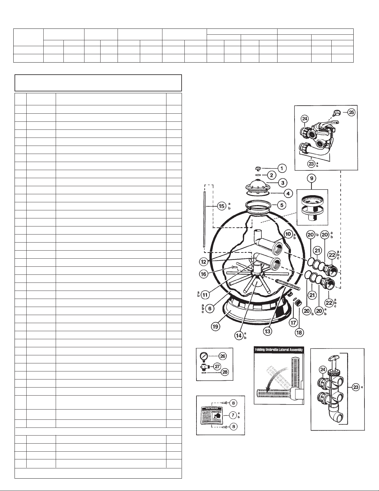
PARTS
Models S311SX, S311SXV, S360SX
REF.
NO.
1
2
3
4
5
6a
6b
6c
6d
7a
7b
8
9
10a
10b
11a
11b
12a
12b
13
14a
14b
15a
15b
16
17
18
19
20a
20b
21
22a
22b
22c
23a
23b
24
25
26
27
---28
NO.
REQ’D.
1
1
1
1
1
1
1
1
1
1
1
2
1
1
1
1
1
2
2
10
1
1
1
1
1
1
1
1
2
4
2
2
2
2
1
1
2
1
1
1
1
1
PART
NO.
SX200G
SX200Z5
SX244KN
GMX600F
SX310N
SX311AA2
SX311AA2FW
SX360AA2
SX360AA2FW
SX311G
SX360G
SX311Z1
SX244G
SX311CD1
SX311CD1FW
SX311CD2
SX311CD2FW
SX360CD
SX360CDFW
SX310HA
SX311DA
SX242MA3
CX1100Z4
SX360Z2
SX200Z2
SX180G
SX180H
SX310J
SX220Z3
SX360Z1
SX360E
DEX360F
SX244P
SX311F
SP0710X62
SP0715X62
SX200Z4
ECX270861
ECX270861
DEX2400S
DEX2400Z3A
SX200Z5
DESCRIPTION
Manual Air Relief Cap
O-Ring, 3/16” O.D.
Top Closure Dome, Noryl
®
Valve/Tank O-Ring
Flange Clamp (Valve/Tank)
Filter Tank (S311 - 1995 and Prior)
Filter Tank (S311 - After 1996)
Filter Tank (S360 - 1999 and Prior)
Filter Tank (S360 - After 1999)
Label Plate with Label (S311)
Label Plate with Label (S360)
Label Plate Screws
Top Diffuser Assembly
Top Elbow Assembly (S311 - 1995 and Prior)
Top Elbow Assembly (S311 - After 1996))
Bottom Elbow Assembly (S311 - 1995 and Prior)
Bottom Elbow Assembly (S311 - After 1996)
Elbow Assembly, Top & Bottom (S360 - 1999 and Prior)
Elbow Assembly, Top & Bottom (S360 - After 1999)
Lateral
Folding Umbrella Lateral Holder Assembly (S311 - 1997 - ) ***
Folding Umbrella Lateral Holder Assembly (S360) - ***
Plastic Air Tube (S311)
Air Tube (S360)
Air Tube Lock Screw
Gasket
Drain Cap
Filter Support Stand
O-Ring (S311 - 1995 and Prior)
O-Ring (S311, S360 - After 1995)
O-Ring Spacer (S311, S360 - After 1995)
Bulkhead Fitting (S311 - 1995 and Prior)
Bulkhead Fitting (S311 - After 1996, S360 - After 1999)
Bulkhead Fitting (S360 - 1999 and Prior)
Vari-Flo Valve Assembly —1-1/2” FIP(Optional)
Vari-Flo Valve Assembly —2” FIP(Optional)
Slide Valve Assembly —2” SKT (Included for S311SXV,
Optional for S311SX & S360SX)
O-Ring
Pressure Gauge
Pressure Gauge
Relief Valve/Gauge Adapter Assembly
O-Ring for Relief Valve Stem (Set of 3)
Relief Valve Assembly O-Ring
Optional (Supplied with Model S311SXV Slide Valve Unit Only)
*Based on 20 GPM/ft2 (maximum allowable NSF rating).
**Also known as No. 20 or No. 1/2 Silica Sand.
SPECIFICATIONS
MODEL
NUMBER
S311SX/SXV
S360SX
EFFECTIVE
FILTRATION AREA
FT
2
M
2
4.95 0.46
6.68 0.62
DESIGN
FLOW RATE*
GPM LPM
99 375
133 503
PRESSURE LOSS AT
DESIGN FLOW RATE
PSI BAR
4.8 0.34
8.6 0.6
MAXIMUM WORKING
PRESSURE
PSI BAR
50 3.45
50 3.45
REQUIRED CLEARANCE
SIDE ABOVE
INCH MM INCH MM
18 457 18 457
18 457 18 457
MEDIA REQUIRED
TYPE AMOUNT
FILTER SAND** LBS KGS
0.45-0.55 350 159
0.45-0.55 700 318
*** See Diagram A
DIAGRAM A
23c SP0410X602S
1
Page 3

Assemble pump and pump mounting base (if supplied) to
the filter according to instructions packed with the base.
Loading sand media. Filter sand media is loaded through
the top opening of the filter.
Remove the top diffuser from the internal diffuser elbow
pipe and place flexible automatic air relief tube to the
side, out of the way, inside the tank.
Cap the internal diffuser elbow pipe with sand shield
provided to prevent sand from entering it. DO NOT
MOVE ELBOW PIPE as this can affect the integrity of
the bulkhead seal.
It is good practice to fill tank approximately 1/2 way with
water to provide a cushioning effect when the filter sand
is poured in. This helps protect the underdrain laterals
from excessive shock. (Be sure the drain cap is securely
in place on drain pipe.) Note: Check to confirm all
laterals are in the down position before loading with
sand. (See Figure A on Page 2.)
Carefully pour in correct amount and grade of filter
sand, as specified. Sand surface should be leveled and
should come to about the middle of the filter tank. Use
no more than the recommended amount of sand.
Remove sand shield from internal diffuser elbow pipe.
Replace diffuser on internal diffuser elbow pipe,
positioning automatic air relief tube through the hole
provided in the diffuser.
Place stainless steel valve flange clamp around neck of
tank. Do not overtighten. Wipe filter flange clean.
Insert Top Closure Dome (with flange O-ring in place)
into the tank neck. Place clamp around dome flange
and tank flange and tighten with screwdriver, tapping
around clamp with screwdriver handle to help seat
flange clamp.
Connect pump to control valve opening marked PUMP
according to instructions. Make return to pool pipe
connection to control valve opening marked RETURN and
complete other necessary plumbing connections, suction
lines to pump, waste, etc.
Make electrical connections to pump per pump instructions.
To prevent water leakage, be sure drain cap is securely in
place and all pipe connections are tight.
INITIAL START-UP OF FILTER
Be sure correct amount of filter sand media is in tank and
that all connections have been made and are secure.
Depress Vari-Flo control valve handle and rotate to BACK
WASH* position. (To prevent damage to control valve seat,
always depress handle before turning).
Prime and start pump according to pump instructions (be
sure all suction and return lines are open), allowing the
filter tank to fill with water. CAUTION: All suction and
discharge valves must be open when starting the
system. Failure to do so could cause severe personal
injury and/or property damage. Once water flow is
steady out the waste line, run the pump for at least 2
minutes. This initial backwashing of the filter is
recommended to remove any impurities or fine sand
particles in the sand media.
Turn pump off and set valve to RINSE position (Vari-Flo
Control Valve only). Start pump and operate until water in
sight glass is clear—about 1/2 to 1 minute. Turn pump off,
set valve to FIL TER position and restart pump. Your filter is
now operating in the normal filter mode, filtering particles
from the pool water.
Adjust pool suction and return valves to achieve desired
flow. Check system and filter for water leaks and tighten
connections, bolts, nuts, as required.
Note the initial pressure gauge reading when the filter is
clean. (It will vary from pool to pool depending upon the
pump and general piping system). As the filter removes dirt
and impurities from the pool water, the accumulation in the
filter will cause the pressure to rise and flow to diminish.
When the pressure gauge reading is 6-8 PSI (0.41-0.55
BAR) higher than the initial “clean” pressure you noted, it
is time to backwash (clean) the filter (see BACKWASH
under Filter Control Valve Functions).
NOTE: During initial clean-up of the pool water it may be
necessary to backwash frequently due to the unusually
heavy initial dirt load in the water.
IMPORTANT: To prevent unnecessary strain on piping
system and valving, always shut off pump before
switching Filter Control Valve positions.
To prevent damage to the pump and filter and for proper
operation of the system, clean pump strainer and skimmer
baskets regularly.
FILTER CONTROL VALVE FUNCTIONS
FILTER—Set valve to FILTER for normal filtering. Also use for
regular vacuuming.
BACKWASH—For cleaning filter. When filter pressure gauge
rises 6-8 PSI (0.41-0.55 BAR) above start-up (clean pressure):
Stop the pump, set valve to BACKWASH. Start pump and
backwash approximately 2 minutes or less depending on dirt
accumulation, until water in sight glass is clear. Proceed to
RINSE.
RINSE—After backwashing, with pump off, set valve to RINSE.
Start pump and operate for about 1/2 to 1 minute. This ensures
that all dirty water from backwashing is rinsed out to the filter to
waste, preventing possible return to the pool. Stop pump, set
valve to FILTER, and start pump for normal filtering.
WASTE—To bypass filter for draining or lowering water level
and for vacuuming heavy debris directly to waste.
RECIRCULATE—Water is recirculated through the pool
system, bypassing the filter.
CLOSED—Shuts off flow from pump to filter.
VACUUMING—Vacuuming can be performed directly into the
filter. When vacuuming heavy debris loads, set valve to
WASTE position to bypass the filter and vacuum directly out to
waste.
FILTER CONTROL SLIDE VALVE -Two positions
FILTER and BACKWASH selections are provided for all
necessary operational functions.
FILTER—Set Valve to FILTER for normal filtering. Also use for
vacuuming (handle in DOWN position).
BACKWASH—For pressure cleaning filter (handle in UP
position).
3.
4.
a.
b.
c.
d.
e.
f.
g.
h.
5.
6.
7.
1.
2.
3.
4.
*NOTE: For new concrete or gunite pools, or where there is a large amount of plaster dust or debris—start filter in FILTER position (not BACKWASH) to prevent clogging of
underdrain laterals.
5.
6.
Page 4

WINTERIZING
Completely drain tank by unscrewing drain cap at base
of filter tank. Leave cap off during winter.
Depress control valve handle (if used) and rotate so as
to set pointer on valve top between any two positions.
This will allow water to drain from the valve. Leave
valve in this “inactive” position.
Drain and winterize pump according to pump
instructions.
SERVICE & REPAIRS
Consult your local authorized
Hayward
dealer or service
center. No returns may be made directly to the factory
without the expressed written authorization of Hayward
Pool Products, Inc.
1.
2.
3.
PLEASE REALIZE . . .
Pure, clear swimming pool water is a combination of two
factors—adequate filtration and proper water chemistry
balance. One without the other will not give the clean water
you desire.
Your filter system is designed for continuous operation.
However, this is not necessary for most swimming pools.
You can determine your filter operation scheduled based on
your pool size and usage. Be sure to operate your
filtration system long enough each day to obtain at least
one complete turnover of your pool water.
To properly sanitize your pool, maintain a free chlorine level
of 1 to 3 ppm and a pH range of 7.2 to 7.6. Insufficient
chlorine or an out of balance pH level will permit algae and
bacteria to grow in your pool and make it difficult for your
filter to properly clean the pool water.
PROBLEM SOLVING LIST
LOW WATER FLOW SHORT FILTER CYCLES POOL WATER WON’T CLEAR UP
Check skimmer and pump
strainer baskets for debris.
Check for restrictions in
intake and discharge lines.
Check for air leak in intake
line (indicated by bubbles
returning to pool).
Backwash filter.
Check for algae in pool and
superchlorinate as required.
Be sure chlorine and pH
levels are in proper range
(adjust as required).
Check surface of filter sand
for crusting or caking (remove
1” of sand if necessary).
Check chlorine, pH and total
alkalinity levels and adjust
as required.
Be sure flow rate through
filter is sufficient.
Operate filter for longer periods.
Be sure Vari-Flo valve is set
on “Filter” position.
1.
2.
3.
4.
1.
2.
3.
1.
2.
3.
4.
REMEDY
POOL CHEMISTRY GUIDELINES
ACTION REQUIRED TO CORRECT POOL CHEMISTRY
TO RAISE
TO LOWER
SUGGESTED POOL CHEMISTRY LEVELS
pH
TOTAL ALKALINITY
CHLORINE (UNSTABILIZED)
CHLORINE (STABILIZED)
CHLORINE STABILIZER
(Cyanuric Acid)
7.2 to 7.6
100 to 130 ppm
0.3 to 1.0 ppm
1.0 to 3.0 ppm
40 to 70 ppm
Add Soda Ash
Add Sodium Bicarbonate
Add Chlorine Chemical
Add Chlorine Chemical
Add Stabilizer
Add Muriatic Acid or Sodium Bisulphate
Add Muriatic Acid
No action - chlorine will naturally dissipate
No action - chlorine will naturally dissipate
Dilution - partially drain & refill pool with water
that has not been treated with Cyanuric Acid.
©2000 Hayward Printed in U.S.A.
Rev. 1/00 B
 Loading...