

Hayward Pro Logic®, Pro Logic PL-PS-4-CUL, Pro Logic PL-PS-16-CUL, Pro Logic PL-PS-8-CUL, PL-PS-4 Installation Manual
...
Pro Logic
Automation and Chlorination
PL-PS-4 PL-PS-8-V
PL-PS-8 PL-PS-16-V
PL-PS-16
Installation Manual
for models
www.haywardnet.com
IMPORTANT SAFETY INSTRUCTIONS
!
!
!
When using this electrical equipment, basic safety precautions should always be
followed, including the following:
•
•
•
•
• A green colored terminal marked “Grounding” is located inside the wiring
• One bonding lug for US models (two for Canadian models) is provided on the
READ AND FOLLOW ALL INSTRUCTIONS
WARNING: Disconnect all AC power during installation.
WARNING: Water in excess of 100 degrees Fahrenheit may be
hazardous to your health.
WARNING: To reduce the risk of injury, do not permit children to
use this product unless they are closely supervised at all times.
compartment. To reduce the risk of electric shock, this terminal must be
connected to the grounding means provided in the electric supply service
panel with a continuous copper wire equivalent in size to the circuit conductors
supplying the equipment.
external surface. To reduce the risk of electric shock, connect the local
common bonding grid in the area of the swimming pool, spa, or hot tub to
these terminals with an insulated or bare copper conductor not smaller than 8
AWG US / 6 AWG Canada.
• All field installed metal components such as rails, ladders, drains, or other
similar hardware within 3 meters of the pool, spa or hot tub shall be bonded to
the equipment grounding bus with copper conductors not smaller than 8 AWG
US / 6 AWG Canada.
• SAVE THESE INSTRUCTIONS

Table of Contents
Introduction Before You Begin................................................................... 1
Installation Steps.................................................................... 2
1. Preparing General Water Chemistry..................................................... 3
Pool/Spa Water Salt.......................................................................................... 4
2. Mounting Pro Logic Control Center................................................... 5
Equipment PS-16 Expansion Unit.......................................................... 6
Temperature Sensors........................................................... 6
Optional Chlorination Function............................................ 6
Optional AQL-CHEM ORP and pH Sensing Kit................ 6
Optional AQL-COLOR-MODHV Network Module............. 6
Optional Wired Remote Display/Keypad........................... 7
Optional Wireless Remote Display/Keypad....................... 7
Optional Base Station........................................................... 7
Optional Valve Actuators....................................................... 7
3. Plumbing “Standard” Pool/Spa Configuration..................................... 8
“Dual Equipment” Pool/Spa - Separate Heaters............... 9
“Dual Equipment” Pool/Spa - Shared Heaters................... 10
Turbo Cell............................................................................... 11
Flow Switch............................................................................ 11
4. Electrical Main Service.......................................................................... 12
Wiring Grounding and Bonding........................................................ 12
Circuit Breaker Installation and Wiring................................ 12
General Purpose Outlet........................................................ 12
Pro Logic Control Power................................................... 13
High Voltage Pool Equipment.............................................. 13
Low Voltage Wiring............................................................... 15
5. Configuration Group Function...................................................................... 22
Configuration Menus............................................................. 24
Maintenance Menu................................................................ 40
6. System Startup Before Startup........................................................................ 41
and Checkout Heater Checkout.................................................................... 41
Service Mode........................................................................ 42
7. Warranty Pro Logic Limited Warranty................................................. 44

Introduction
Before You Begin
What’s Included
Before attempting to install the Pro Logic system, check that the following components have been included in the
package:
Pro Logic Electronics Unit
(3) Temperature sensors with 15 ft. (5m) cable, hose clamp
Pro Logic Expansion Unit (PS-16 only)
What’s NOT Included
Some of the additional items that you may need to complete an installation include:
Circuit breakers
None are included with control—see page 12 and inside of door for suitable breakers
Wire
4-conductor cable (electronics unit to remote display/keypad)
Wire/conduit for 100A service from main panel to Pro Logic
Wire/conduit for filter pump and other high voltage loads
Wire for bonding
Miscellaneous
Utility electrical outlet and weatherproof cover (for mounting on side of Pro Logic)
Mounting hardware (screws, etc.) for mounting Pro Logic and remote display/keypad
Valves (use standard Hayward, Pentair/Compool, or Jandy valves)
Additional valve actuators
Accessory Products - Order Separately
T-CELL-3 Pick N MixTM Chlorinator Cell (for pools up to 15k gallons)
T-CELL-9 Pick N Mix Chlorinator Cell (for pools up to 25k gallons)
T-CELL-15 Pick N Mix Chlorinator Cell (for pools up to 40k gallons)
P-KIT Chlorination Plumbing Kit containing flow switch and cell unions
AQL-CHEM ORP & pH sense kit
AQL-CHEM2(-240) pH dispense kit
AQL2-Wx-PS-4 Wired Remote Display (see note 1)
AQL2-Wx-PS-8 Wired Remote Display (see note 2)
AQL2-Wx-PS-16 Wired Remote Display (see note 3)
AQL2-POD Handheld Wireless Remote Control (see note 4)
AQL2-Wx-RF-PS-4 Wireless Wallmount Remote Control (see notes 1, 4, 5)
AQL2-Wx-RF-PS-8 Wireless Wallmount Remote Control (see notes 2, 4, 5)
AQL2-Wx-RF-PS-16 Wireless Wallmount Remote Control (see notes 3, 4, 5)
AQL2-Tx-RF-PS-4 (x=W/B) Wireless Table Top Remote Control, specify color - white or black (see notes 1,4,5)
AQL2-Tx-RF-PS-8 (x=W/B) Wireless Table Top Remote Control, specify color - white or black (see notes 2,4,5)
AQL2-Tx-RF-PS-16(x=W/B) Wireless Table Top Remote Control, specify color - white or black (see notes 3,4,5)
AQL-SS-6B-x (x=W/B) Wired Spa Side 6 Function Remote Control, 150ft cable, spec. color (white or black)
AQL-SS-D-x (x=W/B) Wired Spa Side 8 Function Remote Control, 150ft cable, spec. color (white or black)
AQL2-SS-RF Wireless Spa Side Remote Control (see note 4)
AQL2-BASE-RF Base Station
AQL-DIM Light Dimmer Relay
AQL-COLOR-MODHV ColorLogic Network Module for 120V Generation 4 ColorLogic lights
GVA-24 Valve Actuator
V&A-xx Valve & Actuator (xx=1P (1.5” pos. seal), -2P (2” pos. seal))
GLX-PC-12-KIT 10K thermistor sensor w/15’ leads, (necessary if both solar and dual equipment is desired)
Notes: 1. for use with PS-4 model only
2. for use with PS-8 model only
3. for use with PS-16 model only
4. requires base station AQL2-BASE-RF
5. 9V wall plug-in power supply included
1 42

NOTE: Before installing this product as part of a saline water purification system in a pool or spa using natural
stone for coping or for immediately adjacent patios/decking, a qualified stone installation specialist should be
consulted regarding the appropriate type, installation, sealant (if any) and maintenance of stone used around a
saline pool with electronic chlorine generator in your particular location and circumstances.
NOTE: The use of dry acid (sodium bisulfate) to adjust pool pH is discouraged especially in arid regions where
pool water is subject to excessive evaporation and is not commonly diluted with fresh water. Dry acid can cause a
buildup of by-products that can damage your chlorinator cell.
Installation Steps
Details on each installation step are presented on the following pages:
1. Prepare the pool water (page 3)
General Water Chemistry
Salt
2. Mounting the equipment (page 5)
Pro Logic main unit
Temperature sensors
Remote display/keypad (optional)
Valve actuators (if applicable)
3. Plumbing (page 8)
General Pool Equipment
Chlorinator Turbo Cell
Flow Switch
4. Electrical Wiring (page 12)
Main service
Grounding and bonding
Circuit breakers
Pro Logic control power
High Voltage pool equipment
Low voltage wiring (temperature sensors, flow switch, etc.)
5. Pro Logic control configuration (program desired control operation) (page 22)
6. System Startup and checkout (page 41)
241
ºC ºF Ti
Calcuim
Hardness
Ci
To ta l
Alkalinity
Ai
53
60
66
76
84
94
103
12
16
19
24
29
34
39
.3
.4
.5
.6
.7
.8
.9
How to use:
Ai from your measurements. Insert values of pH, Ti, Ci and Ai
may occur.
1
0.2
CORROSIVE SCALING
75 75
100 100
125 125
150 150
200 200
250 250
300 300
400 400
600 600
800 800
1.5 1.9
1.6 2.0
1.7 2.1
1.8 2.2
1.9 2.3
2.0 2.4
2.1 2.5
2.2 2.6
2.4 2.8
2.5 2.9
1. Preparing Pool/Spa Water
VSP Speed
%
Toggle between % and RPM
Move to
variable speed pump
Reset ColorLogic to
Default Press +
Are you sure?
+ to proceed
ColorLogic. reset
Confirmed
Initiate reset of ColorLogic configuration parameters
Reset all configuration parameters
Move to previous/next configuration
Move to previous/next menu (config. not reset)
Move to previous/next configuration menu
Reset Config. to
Default Press +
Are you sure?
+ to proceed
Config. reset
Confirmed
Reset all configuration parameters
Move to previous/next configuration
Move to previous/next menu (config. not reset)
Move to previous/next configuration menu
pH Calibration
Wizard, + to enter
Move to previous/next menu item
Clean Probe Wizard
+ to enter
Move to previous/next menu item
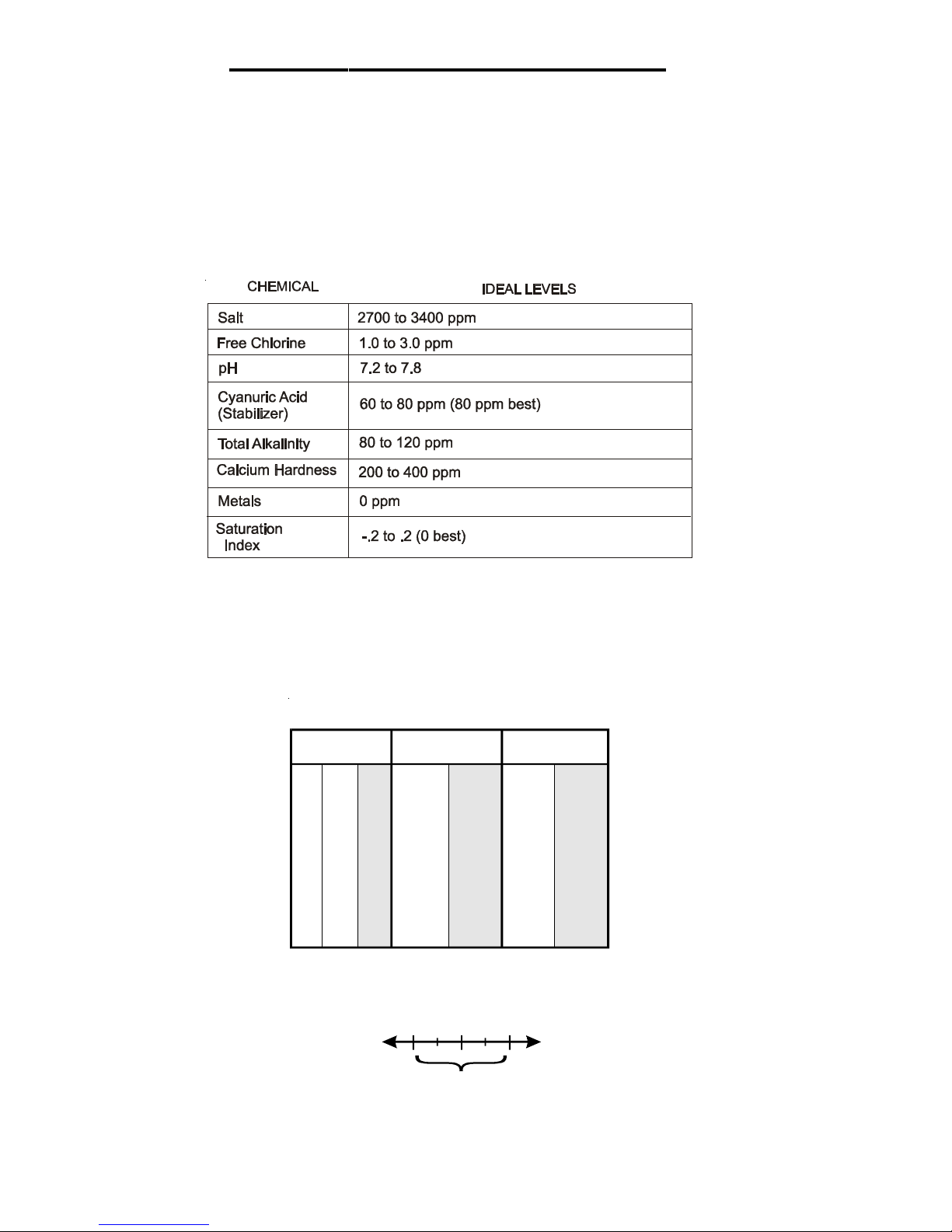
General Water Chemistry
Salt is required only if you are using the chlorinator features on the Pro Logic Control. If you are NOT using the
chlorinator, it is recommended that you follow all of the other chemistry recommendations besides salt. Refer to the
description of the Pro Logic configuration menu for information on enabling/disabling the chlorinator (see page 24).
Water Chemistry
The table below summarizes the levels that are recommended by the Association of Pool and Spa Professionals
(APSP). The only special requirements for the Pro Logic are the salt level and stabilizer.
Saturation index
The saturation index (Si) relates to the calcium and alkalinity in the water and is an indicator of the pool water
“balance”. Your water is properly balanced if the Si is 0 ±0.2. If the Si is below -0.2, the water is corrosive and
plaster pool walls will be dissolved into the water. If the Si is above +0.2, scaling and staining will occur. Use the
chart below to determine the saturation index.
and total alkalinity. Use the chart above to determine Ti, Ci,and
into the above equation. If Si equals .2 or more, scaling and
staining may occur. If Si equals -.2 or less corrosion or irritation
The pool’s chemistry must be balanced BEFORE activating the Pro Logic’s optional chlorinator function. NOTE:
If the pool does not have new water, add metal remover and non-copper based algaecide to the pool, per
manufacturer’s instructions. This ensures a quick, troublefree transfer to the Pro Logic system.
Si = pH + Ti + Ci + Ai - 12.
Measure pool pH, temperature, calcium hardness,
-.2
OK
3
Gall
o
n
s
a
n
d
(
L
i
t
e
r
s
)
o
f
P
o
o
l
/
S
p
a
w
ate
r
12,000 14,000 16,000
1
8
,
0
0
020
,
0
002
2
,
0
0
0
3
2
,
0
0
0
2
4
,
0
0
034
,
0
0
0
2
6
,
0
0
0
3
6
,
0
0
0
2
8
,
0
0
0
3
8
,
0
0
0
3
0
,
0
0
0
4
0
,
0
0
0
Current salt
level
(45000) (52,500) (60,000)
(
6
7
,
5
0
0
)
(
7
5
,
0
0
0
)
(
8
2
,
5
0
0)(
1
2
0
,
0
0
0
)
(
9
0
,
0
0
0)(
1
2
7
,
5
0
0
)
(
9
7
,
5
0
0)(
1
3
5
,
0
0
0)(
1
0
5
,
0
0
0
)
(
1
4
2
,
5
0
0
)
(
1
1
2
,
5
0
0
)
(
1
5
0
,
0
0
0
)
ppm
0
320
(145)
373
(170)
427
(194)
4
8
0
(
2
18)
(242)
587 854
(267) (388)
640 907
(291) (412)
693 960
(315) (436)
747
(339) (4
6
0
)
800
1
0
6
7
(364)
(
4
8
4
)
200
300
(136)
350
(159)
400
(182)
450
(205)
500
(227)
550 800
(250)
(363)
600 850
(273) (385)
650 900
(295) (408)
700 9
5
0
(318) (4
3
0
)
750
1
0
0
0
(341)
(
4
5
3
)
400
280
(127)
327
(148)
373
(170)
420
(191)
467
(212)
513 747
(233) (339)
560 793
(255) (360)
607 840
(276) (382)
653 8
8
7
(297) (4
0
3
)
700
9
3
3
(318)
(
4
2
4
)
600
260
(118)
303
(138)
347
(158)
390
(177)
433
(197)
477 693
(217) (317)
520 737
(236) (337)
563 780
(256) (358)
607 8
2
3
(276) (3
7
8
)
650
8
6
7
(297)
(
3
9
8
)
800
240
(109)
280
(127)
320
(145)
360
(164)
400
(182)
440 640
(200) (291)
480 680
(218)
(310)
520 720
(236) (328)
560 76
0
(255) (3
4
6
)
600
8
0
0
(273)
(
3
6
4
)
1000
220
(100)
257
(117)
293
(133)
330
(150)
367
(167)
403 587
(183) (267)
440 623
(200) (283)
477 660
(217) (300)
513 69
7
(233) (3
1
7
)
550
7
3
3
(250)
(
3
3
3
)
1200
200
(91)
233
(106)
267
(121)
300
(136)
333
(152)
367 533
(167) (243)
400 567
(182) (258)
433 600
(197) (274)
467 63
3
(212) (2
8
9
)
500
6
6
7
(227)
(
3
0
4
)
1400
180
(82)
210
(95)
240
(109)
270
(123)
300
(136)
330 480
(150) (218)
360 510
(164) (232)
390 540
(177) (246)
420 57
0
(191) (2
5
9
)
450
6
0
0
(205)
(
2
6
3
)
1600
160
(73)
187
(85)
213
(97)
240
(109)
267
(121)
293 427
(133)
(195)
320 453
(145) (207)
347 480
(158) (219)
373 50
7
(170) (2
3
1
)
400
5
3
3
(182)
(
2
4
3
)
1800
140
(64)
163
(74)
187
(85)
210
(95)
233
(106)
257 373
(117) (169)
280 397
(127) (180)
303 420
(138) (190)
327 44
3
(148) (20
1
)
350
4
6
7
(159)
(
2
1
1
)
2000
120
100
80
60
20
40
(55)
(45)
(36)
(27)
(9)
(18)
140
117
23
47
(64)
(53)
(11)
(21)
160
133
27
53
(73)
(61)
(12)
(24)
180
150
30
60
(82)
(68)
(14)
(27)
200
167
33
67
(91)
(76)
(15)
(30)
220 320
183 267
37 53
73 107
(100) (145)
(83) (121)
(17) (24)
(33) (48)
240
340
200 283
40
57
80 113
(109) (154)
(91) (129)
(18) (26)
(36) (51)
260 360
217 300
43 60
87 120
(118) (163)
(98) (137)
(20) (27)
(39) (54)
280 38
0
233 31
7
47
6
3
93
1
2
7
(127) (17
2
)
(106) (1
4
4
)
(21) (2
9
)
(42) (5
7
)
300
4
0
0
250
3
3
3
50
6
7
100
1
3
3
(136)
(
1
8
1
)
(114)
(
1
5
2
)
(23)
(
3
0
)
(45)
(60
)
(32)
80
(36)
90
(41)
100
(45)
1
1
0
1
6
0
(
5
0
)
(
7
3
)
1
2
0
1
7
0
(
5
5
)
(
7
7
)
1
3
0
1
8
0
(
5
9
)
(
8
1
)
1
4
0
1
9
0
(
6
4
)
(
8
6
)
1
5
0
2
0
0
(
68)
(
9
0
)
93
(42)
107
(48)
120
(55)
133
(61)
1
4
7
2
1
3
(
67)
(98
)
1
6
0
22
7
(
7
3
)
(
1
0
4
)
1
7
3
2
4
0
(
7
9
)
(
1
1
0
)
1
8
7
2
5
3
(
8
5)(
1
17)
2
0
0
2
6
7
(
9
1
)
(
1
2
3
)
2200
3000
2800
2400
3200
Ideal Ideal Ideal Ideal Ideal
I
d
e
alI
d
e
a
l
I
d
e
alI
d
e
a
l
I
d
e
alI
d
e
a
l
I
d
e
alI
d
e
a
l
I
d
e
a
l
I
d
e
a
l
2600
3400
OK
OK
OK
OK
OK OK OK
O
K
O
KOK
OKO
K
OKO
K
O
K
O
K
O
K
P
OUN
D
S
a
n
d
(
K
g
)
OF
S
A
L
T
N
E
E
D
E
D
F
OR
3
2
0
0
P
P
M
3600+
Dilute Dilute Dilu
t
e
D
i
l
u
t
e
D
i
l
u
t
e
D
i
l
u
t
e
D
i
l
u
teD
i
l
u
t
e
D
i
l
u
teD
i
l
u
t
e
D
i
l
u
t
e
D
i
l
u
t
e
D
i
l
u
t
e
D
i
l
u
t
e
D
i
l
u
t
e
10,000
8,000
(37,500)
213
267
(97)
(121)
200 250
(91) (114)
187 233
(85)
(106)
173
217
(79)
(98)
160 200
(73)
(91)
147 183
(67) (83)
133 167
(61) (76)
120 150
(55) (68)
107 133
(48) (61)
93 117
(42) (53)
80 100
67 83
53
67
40 50
13 17
27 33
(36) ( 45)
(30) (38)
(24) (30)
(18) (2 3)
(6) (8 )
(12)
(15)
Ideal
Ideal
Dilute
Dilute
(30,000)
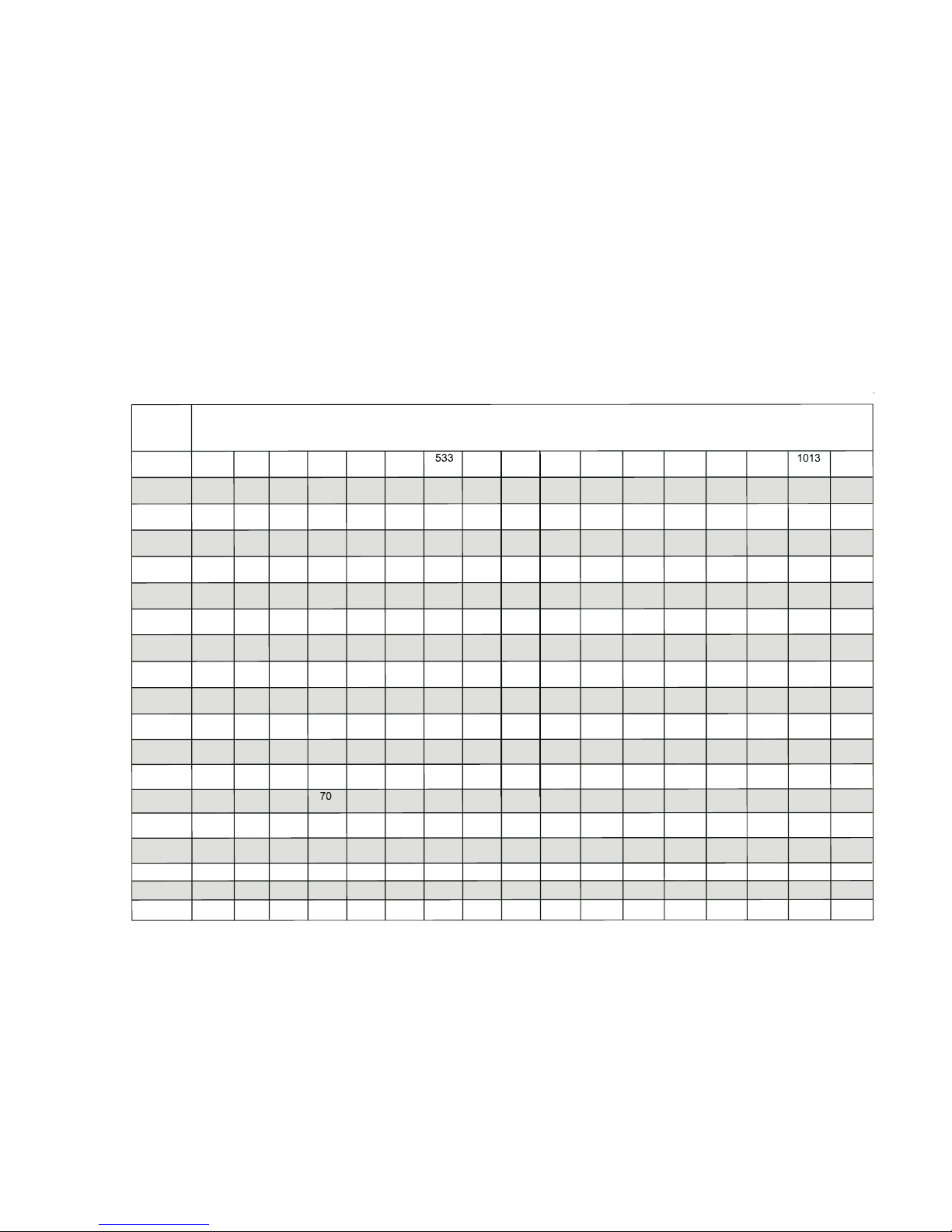
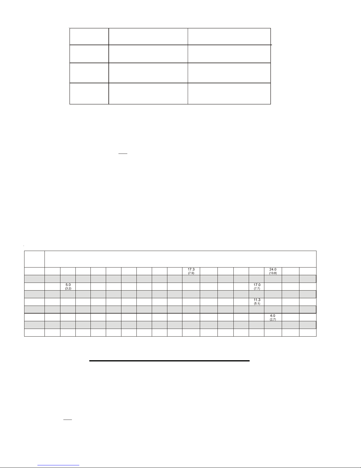
Salt (When using optional chlorinator function)
Salt Level
Use the chart below to determine how much salt in pounds or (Kgs) should be added to reach the recommended
levels. Use the equations on the following page (measurements are in feet/gallons and meters/liters) if pool size is
unknown.
The operating salt level is between 2700-3400 PPM (parts per million) with 3200 PPM being optimal. Before
adding any salt, test the salt level. This is especially important for retrofit installation to older pools where all of the
chlorine added to the pool over time is ending up as salt. If the level is low, determine the number of gallons in the
pool and add salt according to the chart below. A low salt level will reduce the efficiency of the sanitization and
result in low chlorine production. A high salt level can cause the Pro Logic to stop chlorinating. The salt in your
pool/spa is constantly recycled and the loss of salt throughout the swimming season should be minimal. This loss is
due primarily to the addition of water because of splashing, backwashing, or draining (because of rain). Salt is not
lost due to evaporation.
4
Pool Sizing Formula
Gallons
Liters
Rectangular
Round
Oval
Diameter x Diameter x
Average Depth x 5.9
Length x Width x
Average Depth x 6.7
Length x Width x
Average Depth x 7.5
Average Depth x 785
Length x Width x
Average Depth x 893
Length x Width x
Average Depth x 1000
Gallons and (Liters) of Pool/Spa water
Current
Stabilizer
Level (ppm)
0 ppm
20 ppm
60 ppm
30 ppm
40 ppm
50 ppm
70 ppm
80 ppm
10 ppm
12,000
(45000)
8,000
(30000)
14,000
(52500)
10,000
(37500)
16,000
(60000)
18,000
(67500)
20,000
(75000)
22,000
(82500)
32,000
(120000)
24,000
(90000)
34,000
(127500)
26,000
(97500)
36,000
(135000)
28,000
(105000)
38,000
(142500)
30,000
(112500)
40,000
(150000)
8.0
(3.6)
5.3
(3.6)
8.0
(3.6)
9.4
6.7
(4.3)
9.4
10.7
12.0
12.0
13.4
14.7
21.3
16.0
22.7
(10.3)
18.7
25.3
20.0
(9.1)
26.7
7.0
)
(3.2
4.7
(3.2)
8.2
(3.7)
5.8
(3.7)
10.5
(4.8)
11. 7
(5.3)
12.9
(5.9)
18.7
(8.5)
14.0
(6.4)
19.8
(9.0)
15.2
(6.9)
21.0
(9.5)
16.4
(7.4)
22.2
17.2
(8.0)
23.3
6.0
(2.7)
4.0
(2.7)
6.0
(2.7)
6.0
(2.7)
8.5
(3.9)
7.0
(3.2)
9.0
(2.2)
10.0
(4.5)
10.0
(4.5)
14.2
(6.3)
11. 0
(5.0)
16.0
(7.2)
13.0
(5.9)
18.0
14.0
(6.4)
19.0
15.0
(6.8)
20.0
5.0
(2.3)
3.3
(2.3)
5.0
(2.3)
5.9
(2.7)
4.2
(2.7)
6.7
(3.0)
8.4
(3.8)
6.7
(3.0)
7.5
(3.4)
9.2
(4.2)
13.3
(6.0)
10.8
(4.9)
15.0
11. 7
(5.2)
15.8
12.5
(5.6)
16.7
4.0
(1.8)
2.7
(1.8)
4.0
(1.8)
4.0
(1.8)
5.7
(2.6)
4.7
(2.1)
3.3
(2.1)
5.4
(2.4)
7.4
(3.3)
10.7
(4.8)
8.7
(3.9)
12.0
9.3
(4.2)
12.7
10.0
(4.5)
13.3
3.0
(1.4)
2.0
(1.4)
3.0
(1.4)
3.5
(1.6)
2.5
(1.6)
4.5
(2.0)
5.5
(2.5)
8.0
(3.6)
6.5
(2.9)
9.0
7.0
(3.2)
9.5
7.5
(3.4)
10.0
2.0
(.91)
1.3
(.91)
2.0
(.91)
2.8
(1.3)
2.3
(1.1)
1.7
(1.1)
2.7
(1.2)
3.3
(1.5)
3.7
(1.7)
5.3
(2.4)
4.3
(2.0)
6.3
5.0
6.7
1.0
0.7
(.45)
1.2
0.8
1.4
1.5
1.7
1.8
2.7
2.2
3.0
2.3
3.2
2.5
3.3
0.00.0 0.00.0 0.0 0.0 0.0 0.0
0.00.0 0.00.0 0.00.0 0.00.0 0.0
6B Spa Config.
+ to view/change
6B A, Button 1
Pool/Spa
Select 6B Spa
A
Push to access the 6 Button Spa Side Remote options
Valve4, and all available Aux outputs
Rotates between all available remotes
Move to previous/next configuration menu
Move to previous/next menu item or next configuration menu
Move to next menu item
(pool size in feet)
(pool size in meters)
Diameter x Diameter x
Type of Salt to Use
It is important to use only sodium chloride (NaCl) salt that is greater than 99.0% pure. This can be found at most
pool stores in 40-80 lb. bags labeled “for use in swimming pools”. Alternatively, use common food quality or water
softener salt that is at least 99.0% pure. It is also acceptable to use water conditioning salt pellets, however, it will
take longer for them to dissolve. Do not use rock salt, or salt with more than 1% of yellow prussiate of soda, salt
with anti-caking additives, or iodized salt.
How to Add Salt
For new plaster pools, wait 10-14 days before adding salt to allow the plaster to cure. Turn the circulating pump
on and add salt directly into the pool. Brush the salt around to speed up the dissolving process—do not allow salt
to pile up on the bottom of the pool. Run the filter pump for 24 hours with the suction coming from the main drain
(use pool vacuum if there is no main drain) to allow the salt to evenly disperse throughout the pool. The salt display
may take 24 hours to respond to the change in salt concentration.
Always check stabilizer (cyanuric acid), when checking salt. These levels will most likely decline together. Use the
chart below to determine how much stabilizer must be added to raise the level to 80 ppm.
POUNDS and (Kg) OF STABILIZER (CYANURIC ACID) NEEDED FOR 80 PPM
(4.3)
(4.9)
(4.3)
8.0
(3.6)
(.45)
(.54)
(.54)
(.64)
2. Mounting the Equipment
Pro Logic Control Center
The Pro Logic is contained in a raintight enclosure that is suitable for outdoor mounting. The control must be
mounted a minimum of 5 ft. (2 meters) horizontal distance from the pool/spa (or more, if local codes require). The
Control Center is designed to mount vertically on a flat surface with the knockouts facing downward. Because the
enclosure also acts as a heat sink (disperses heat from inside the box), it is important not to block the four sides of
the control. Do not mount the Pro Logic inside a panel or tightly enclosed area.
When selecting a location, note that the standard cables supplied with the Turbo Cell, flow switch, temperature
sensors, and valve actuators (if applicable) are all 15 ft. (5m) long.
(5.4)
(6.1)
(6.7)
(7.3)
(5.4)
(.68)
(.77)
(.82)
5 38
(1.0)
(2.3)
(1.2)
(9.7)
(1.2)
(8.5)
4.7
(2.1)
(1.1)
(8.1)
(6.7)
(5.4)
(4.1)
(1.3)
(11.5)
(10.0)
(8.6)
(7.1)
(5.7)
(4.3)
(2.8)
(1.4)
(12.0)
(10.5)
(9.0)
(7.5)
(6.0)
(4.5)
(3.0)
(1.5)

PS-16 Expansion Unit
!
For the PS-16, the relays for Aux1-6 are contained in the Pro Logic Control Center. The relays for Aux7-14 are
contained in the PS-16 Expansion Unit. Valve outputs 7-10, in the PS-16 Expansion Unit follow the outputs of
Aux7-10, respectively.
Temperature Sensors
Three sensors are included with the Pro Logic. A water sensor and an air sensor must be installed at all times for
proper operation. An additional supplied sensor can be used for either solar or dual equipment function. If both
solar and dual equipment functions are desired, an additional sensor will need to be purchased.
Water Sensor
This sensor is used to measure the pool/spa temperature and is installed in the filtration plumbing after the filter but
before either the solar or conventionally fueled heaters—refer to the plumbing overview diagram.
1. Drill a 3/8” (10mm) diameter hole in the PVC piping and remove all chips and burrs.
2. Insert sensor until O-ring collar sits flush on the hole.
3. Position hose clamp over the sensor and gently tighten until O-ring makes an adequate seal. Do not overtighten.
4. For maximum temperature accuracy, cover the sensor and 3” (6cm) of pipe on either side with insulation and
white paint.
Air Sensor
Mount the air sensor outdoors.
IMPORTANT: Mount the air sensor out of direct sunlight.
Solar Sensor
For solar applications, mount the sensor near the solar collector array so that it is exposed to the same sunlight as
the collectors (see page 9). Use additional cable (20 AWG) if necessary.
Dual Equipment Spa Sensor
For dual equipment applications (separate filter pumps and heaters for both the pool and the spa), mount the dual
equipment spa sensor after the spa filter but before the heater (see page 9). Use additional cable (20 AWG) if
necessary.
Optional Chlorination Function
The PL-PS-4/8/16 models require the use of a chlorinator cell and plumbing kit to provide pool chlorination.
These items are not included with the Pro Logic and can be purchased separately at your local Hayward dealer.
Choose a chlorinator cell model based on the size of your pool. The following models are available:
T-CELL-15 for pools up to 40,000 gallons
T-CELL-9 for pools up to 25,000 gallons
T-CELL-3 for pools up to 15,000 gallons
In addition to the chlorinator cell, a plumbing kit (P-KIT) must be purchased. This kit contains the cell unions and
flow switch. Refer to pages 11 and 21 for plumbing and wiring instructions.
Optional AQL-CHEM ORP and pH Sensing Kit
The AQL-CHEM is an ORP and pH sensing kit for the Pro Logic. When used with the chlorination function, the
Pro Logic senses the pool's ORP and pH levels and generates the correct amount of chlorine to keep your pool
properly sanitized. Wiring and plumbing requirements for the AQL-CHEM should be considered before installing
the Pro Logic. Refer to the AQL-CHEM manual for specific installation information.
Optional AQL-COLOR-MODHV ColorLogic Network Module
Using the optional AQL-COLOR-MODHV network module, the Pro Logic can fully control the color, speed,
motion and brightness of Hayward ColorLogic Generation 4 pool and spa lights as well as provide programmable
light shows. Refer to the AQL-COLOR-MODHV for detailed installation, wiring and operation information.
6

Optional Remote Controls
OUT
(Common)
IN
(Common)
OUT
OUT
IN
Aux7 Relay
Standard
Move to next menu item or previous/next configuration menu
Aux7 Config.
+ to view/change
Aux7 Function
Group
Aux7 Group
Filter: Unaffected
Aux7 Group
Timer: None(Manual)
Push to access Virtual Aux options
Rotates between Super Chlorinate, Group and Manual On/Off
Options available depend on the function that is selected
Rotates between Manual On/Off (default),Countdown Timer and Timeclock
Move to previous/next configuration menu
Move to next menu item
Move to previous/next menu item or next configuration menu
Move to next configuration menu item
Aux7 Name
Cleaner
Rotates between all available names
Move to next menu item
No Virtual
Hayward offers a variety of wired and wireless remote control options for the Pro Logic. Each model gives you
the ability to control your pool’s functions from a remote location, away from the Control Center.
Wired Remote Controls
Up to 3 wired remote controls can be installed. See “Electrical Wiring” (page 19) for instructions on running the
cable from the Pro Logic main unit to the remote control. Also refer to the remote’s installation instructions for more
information.
AQL2-Wx-PS-x (x=4,8, or 16)
The AQL2-Wx-PS-x is a wall mounted display/keypad which must be mounted indoors or in a weather protected
area (rain should never hit the unit). Note that the number of outputs on the remote (“4”, “8” or “16”) must match
the outputs on the Pro Logic main control unit. This remote control is intended to mount on to a standard electrical
utility box (same box as a triple light switch, ideal for new construction) or can be mounted directly onto any wall
surface. When selecting a location, note that the wire to the Pro Logic main unit must be less than 500’ long.
AQL-SS-6B-x, AQL-SS-D-x (x=W or B for White or Black)
The AQL-SS-6B and AQL-SS-D are double insulated, waterproof devices which are intended for installation at
the water's edge. The remote controls come with an attached 150’ cable and are typically installed at the tile-line
of the spa wall, or in the deck, within arm's reach of a pool/spa occupant.
Wireless Remote Controls
A single Base Station must be installed on the Pro Logic in order to use any of the Hayward wireless remote
controls. There is no limit on the number of wireless remotes that can used. The maximum distance between
wireless remotes and the base station on the Pro Logic main control unit is 400 feet (120m) line of sight or 200 feet
(60m) through walls, etc. If in doubt about the distance, test operation before installing the remote. All wireless
models require the user to run the “Teach Wireless” routine in the Settings Menu. This information can be found in
the Pro Logic Operation Manual and the owner’s manual of each remote.
AQL2-Wx-RF-PS-x (x=4,8, or 16)
The AQL2-Wx-RF-PS-x are wall mounted wireless controls designed to be mounted indoors. These remote
controls come with a wall mounted power supply.
AQL2-Tx-RF-PS-x (x=4,8, or 16)
The AQL2-Tx-RF-PS-x are portable battery operated remote controls designed to be used in a weather protected area (rain should never hit the unit). The AQL2-Tx-RF-PS-x comes with a wall mounted power supply for
recharging the built-in batteries.
AQL2-SS-RF, AQL2-POD
The AQL2-SS-RF and AQL2-POD are waterproof portable remote controls that are designed to be used in and
around the pool/spa area. These units float and can be left in the pool/spa water for easy access.
Optional Base Station
Use the AQL2-BASE-RF for all AQL2 wireless remote controls. To install the base station, remove the knockout
on the upper left side of the Pro Logic main control unit, insert the base station, and then tighten the nut from the
inside. Also refer to the Base Station manual and the diagram on page 20.
Optional Valve Actuators
For optional actuators supplied with the Pro Logic—note that the internal cams in the actuator may also have to be
adjusted depending on the way the actuator is mounted on the valve and the desired valve action.
RETURN
SUCTION
IN
7
3. Plumbing
Pool/ Spa Setup
Pool and Spa-Std
FILTER
SOLAR BOOST
PUMP
SOLAR
VALV E
HEATER
HEAT
PUMP
HEATER
BYPASS
VALV E
(manual )
CELL
FLOW
SWITCH
CHECK
VALV E
PUMP
RETURN
VALV E
WATER
FEATURE
VALV E
SPA
SPA JET
PUMP
SPA
BLOWER
POOL/SPA SUC TION
VALV E
CHECK VALVE
POOL VACUUM
VALV E
MANUAL
VALV E
MANUAL
VALV E
MANUAL
VALV E
ENERGY
FILTER
TWO-WAY
VALV E
SKIM
POP-UP
SPILLOVER
POP-UP
OVERFLOW
POP-UP
RETURN
JET
IN-FLOOR
CLEANER
VALV E
WATE R
FEATURE
PUMP
WATER
FEATURE
POP-UP
MAIN
DRAIN
ENERGY
SAVER
PRESSURE
CLEANER
NON-BOOST
PRESSURE
CLEANER
PRESSURE
CLEANER
SUCTION
CLEANER
SENSOR
FILTER
PUMP
Valve Outputs
Filter Pump
Lights
Aux 1
Aux 2
Pool/Spa Suction
Pool/Spa Return
Val v e 3
Val v e 4
HIGH VOLTAGE
LIGHTS
LOW VOLTAGE
LIGHTS
FIBER OPTIC
LIGHT SOURCE
COLOR WHEEL
ISOLATED
WATE R
FEATURE
PUMP
TEMPERATURE
SENSOR
CHECK
VALV E
(prevents d raining
of raised sp as)
V
of raised sp as)
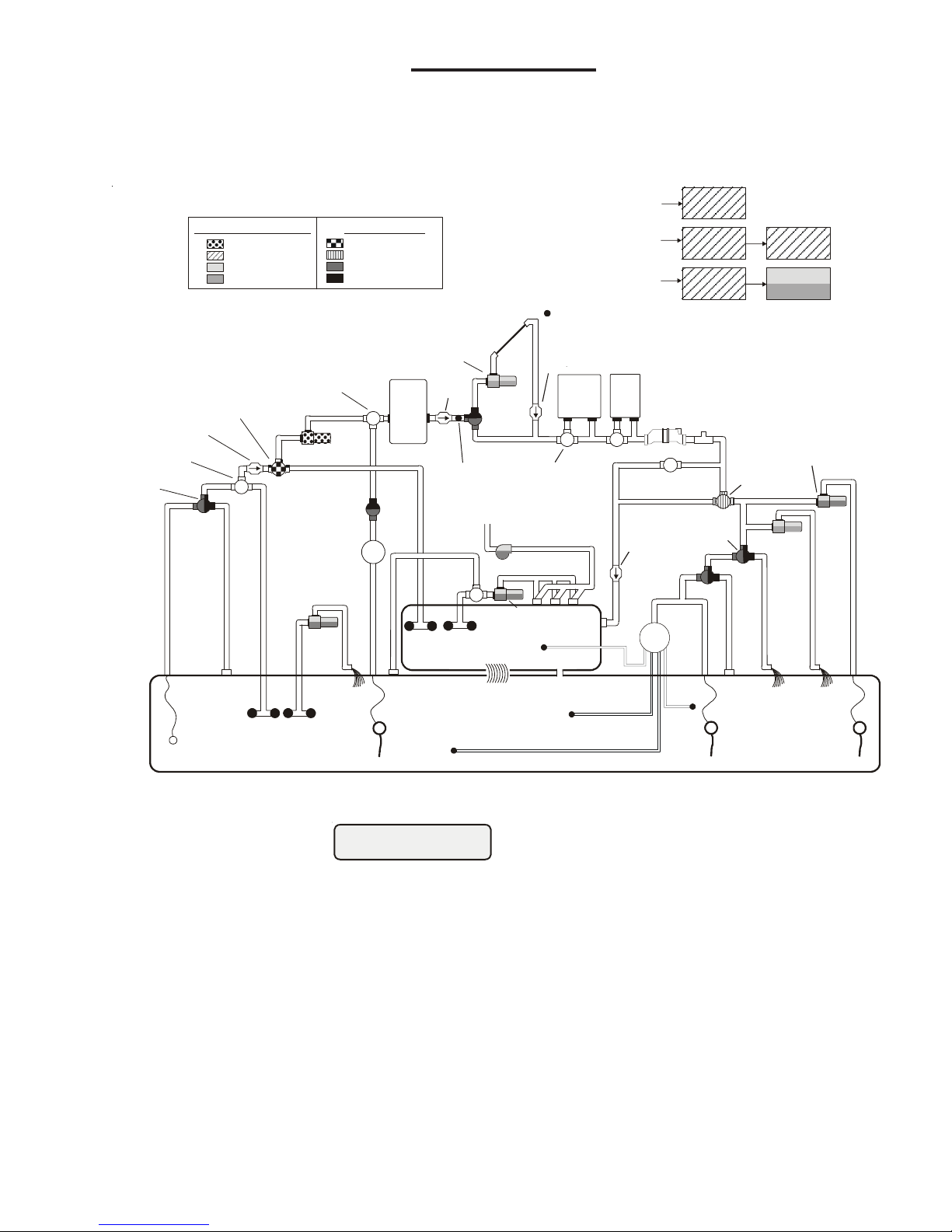
“Standard” Pool/Spa system configuration
These systems use a single filter pump and filter. Pool or spa operation is controlled by two 3-way valves (suction
and return). Refer to the diagram below.
High Voltage Relays
POOL/SPA
POOL
SOLAR
TEMPERATURE
CHECK
ALVE
(prevents d raining
TRANSFORMER
POOL/SPA
POOL SWEEP
BOOST PUMP
WATER
FEATURE
Some important notes regarding the Pro Logic control of Standard Pool/Spa systems:
spa.
chlorinated.
temperature, depending on the current operation of the pool. The temperature will only be displayed when
the filter pump is running.
In Pool/Spa Config., select:
1. The Pro Logic can be programmed to accommodate spa spillover, if desired.
2. Up to two conventional heaters (gas or heat pump) plus solar can be used to heat both the pool and the
3. If the chlorinator cell is plumbed prior to the pool/spa return valve, then both the pool and the spa can be
4. The water sensor should be installed prior to any heater or solar and will display either the pool or the spa
5. If any water feature or pressure side cleaner boost pumps are used, be sure to enable the “interlock”
feature (see “Configuration Menu” for details) to ensure that the pumps operate only when the filter pump
is on and the system is in the “pool only” operating mode.
6. The plumbing diagram above is intended to be used as a general guideline and is not a complete plumbing
schematic for the pool.
7. The air sensor must be installed if the freeze protection feature is enabled for the filter, valves or aux
outputs.
835

“Dual Equipment - Separate Heaters” for Pool/Spa configuration
Pool/Spa Setup
Htr1=Spa,Htr2=Pool
Aux1 Pump Spd
Settings Menu
Move to previous/next configuration menu
if filter pump is set to variable speed
and the relay type is set to standard
Aux1 Config.
+ to view/change
Aux1 Function
Manual On/Off
Aux1 Group
Filter: Unaffected
Aux1 Group
Timer: None(Manual)
Aux1 Name
Cleaner
Aux1 Relay
Standard
Push to access Aux options
Options available depend on the function that is selected
Rotates between all available names
Toggle between Standard (default), Dimmer, ColorLogic and VSP
Move to previous/next configuration menu
Move to previous/next menu item or next configuration menu
Move to next configuration menu item
Move to next menu item
Move to next menu item or previous/next configuration menu
Aux1 Interlock
Disable
Aux1 Freeze
Disable
Toggle between Enabled and Disabled Aux1 Freeze(default)
Move to next menu item
Move to previous/next configuration menu
for all functi ons except solar, dimmer relay,super chlorinate
for all functi ons except solar, dimmer relay,super chlorinate
low speed, group and pH dispense
low speed, group and pH dispense
for all functions except dimmer relay, super chlorinate
low speed, group and ph dispense
for group function only
for group function only
for manual on/off, countdown
timer and timeclock functions
Move to next menu item
Rotates between Manual On/Off (default), Countdown Timer, Low Speed- Filter,
Aux1 Ext Input
Disabled
Toggle between Enabled and Disabled (default)
Move to previous/next configuration menu
!
FILTER
HEATER
HEATER
BYPASS
VALV E
(manual)
HEATER
BYPASS
VALV E
(manual)
PUMP
VALV E
WATE R
FEATURE
VALV E
SPA
SPA JET
PUMP
SPA
BLOWER
POOL VACUUM
VALV E
MANUAL
VALV E
ENERGY
FILTER
TWO-WAY
VALV E
SKIM
POP-UP
SPILLOVER
POP-UP
OVERFLOW
POP-UP
RETURN
JET
IN-FLOOR
CLEANER
VALV E
WATE R
FEATURE
PUMP
WATE R
FEATURE
POP-UP
MAIN
DRAIN
ENERGY
SAVER
PRESSURE
CLEANER
NON-BOOST
PRESSURE
CLEANER
PRESSURE
CLEANER
SUCTION
CLEANER
High Voltage Relays Valve Ou tp ut s
Heater Outputs
Pool Filter Pump
Lights
Spa Filter Pump (Aux 1)
Aux 2 - Aux 6
Pool/Spa Spillover
Val ve 3
Val ve 4
HIGH VOLTAGE
LIGHTS
LO W VO LTAGE
LIGHTS
FIBER OPTIC
LIGHT SOURCE
COLOR WHEEL
ISOLATED
WATER
FEATURE
PUMP
POOL
TEMPERATURE
SENSOR
SPA
TEMPERATURE
SENSOR
HEATER
CELL
FLOW
MANUAL
VALV E
POOL FILTER
PUMP
SPA FILTER
PUMP
V
of raised spas)
for proper spillove r)
Heater 1 (Spa)
SOLAR BOOST
PUMP
SOLAR
VALV E
CHECK
VALV E
SENSOR
V
FILTER
These systems have 2 complete sets of equipment (filter pump, filter, heater)—1 set for the pool and the other set
for the spa. Refer to the diagram below:
Heater 2 (Pool)
CHECK
ALVE
SOLAR
TEMPERATURE
CHECK
ALVE
(prevents draini ng
TRANSFORMER
SWITCH
(adjust cams as nece ssary
POOL/SPA
SPILLOVER
WATER
FEATURE
POOL SWEEP
BOOST PUMP
Some important notes regarding the Pro Logic control of Dual Equipment Pool/Spa systems with separate heaters:
In the Pool/Spa Config., select:
1. When dual equipment is selected:
a. The “Filter” pump automatically is renamed “Pool Filter” and can not be changed. The pool filter
b. The “Aux1” output is automatically renamed “Spa Filter”, its function is set to “Timeclock” and the
c. The Heater1 output should be connected to the spa heater—the heater will only turn on when the
d. The Heater2 output should be connected to the pool heater—the heater will only operate when
2. The water sensor should be installed on the pool loop prior to the heater and will display the pool temperature
whenever the “Pool Filter” pump is running.
3. The dual equipment spa sensor should be installed on the spa loop prior to the heater and will display the
spa temperature whenever the “Spa Filter” pump is running.
4. The Pro Logic can be programmed to accommodate spillover if desired. Note that spillover operation will
be automatically suspended whenever the spa filter pump is turned on.
can be a one, two or variable pump.
Interlock feature is forced to “Disabled”. None of these can be changed. The spa filter can be a
one, two or variable pump.
spa filter pump is running.
the pool filter is running. If the system does not have a pool heater, disable Heater2 in the configuration
menu and then the relay can be used to operate general purpose Valve4.
Pool and Spa-Dual
POOL
9
Heaters
5. The chlorinator cell must be installed in the pool plumbing. If spillover is enabled, then the Pro Logic can
Pool/Spa Setup
Shared
POOL
FILTER
ELECTROLYTIC
CELL
FLOW
SWITCH
POOL FILTER
PUMP
VALV E 1
VALV E 2
V
In from POOL
Out to SPA
Out to POOL
In from SPA
SENSOR
FILTER
PUMP
HEATER
HEATER
SOLAR BOOST
PUMP
SOLAR
VALV E
CHECK
VALV E
SOLAR
TEMPERATURE
SENSOR
CHECK
VALV E
chlorinate both the pool and spa (during spillover operation). Otherwise, the Pro Logic will only chlorinate
the pool and the spa sanitization will have to be handled manually.
6. If any water feature or pressure side cleaner boost pumps are used, be sure to enable the “interlock”
feature (see “Configuration Menu” for details) to ensure that the pumps operate only when the “Pool
Filter” pump is on and the system is in the “pool only” operating mode.
7. The plumbing diagram on page 9 is intended to be used as a general guideline and is not a complete
plumbing schematic for the pool.
8. When using the wireless spa-side remote control (AQL2-SS-RF), the “POOL” button will position the
valves for Pool mode and the “SPA” button will position the valves for Spillover mode.
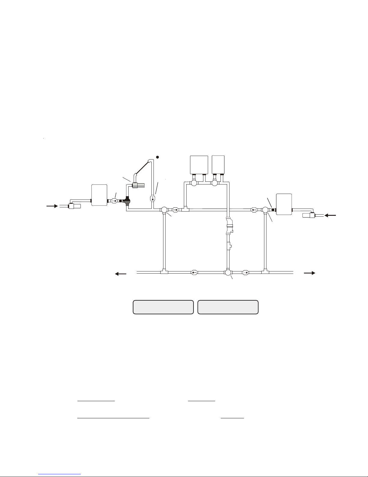
“Dual Equipment - Shared Heaters” for Pool/Spa configuration
These systems have 2 complete sets of equipment (filter pump, filter) and shared heaters. Refer to the diagram
below:
SPA
TEMPERATURE
SPA
SPA FILTER
ALVE 3
Some important notes regarding the Pro Logic control of Dual Equipment Pool/Spa systems with shared heaters:
In the Pool/Spa Config., select:
Pool and Spa-Dual
Heaters
1. When dual equipment is selected:
a. The “filter” pump automatically is renamed “Pool Filter” and can not be changed. The pool filter
can be a one, two or variable pump.
b. The “Aux1” output is automatically renamed “Spa Filter”, its function is set to “Timeclock” and the
Interlock feature is forced to “Disabled”. None of these can be changed. The spa filter can be a
2. The water sensor should be installed on the pool loop prior to the heater(s) and will display the pool
one, two or variable pump.
c. The Valve3 configuration menu is disabled.
d. The heater(s) will be dedicated to the spa whenever the spa filter is on and the spa temperature
setting is not off.
temperature whenever the “Pool Filter” pump is running.
3. The dual equipment spa sensor should be installed on the spa loop prior to the heater(s) and will display
the spa temperature whenever the “Spa Filter” pump is running.
1033
4. The Pro Logic can be programmed to accommodate spillover if desired. Note that spillover operation will
!
!
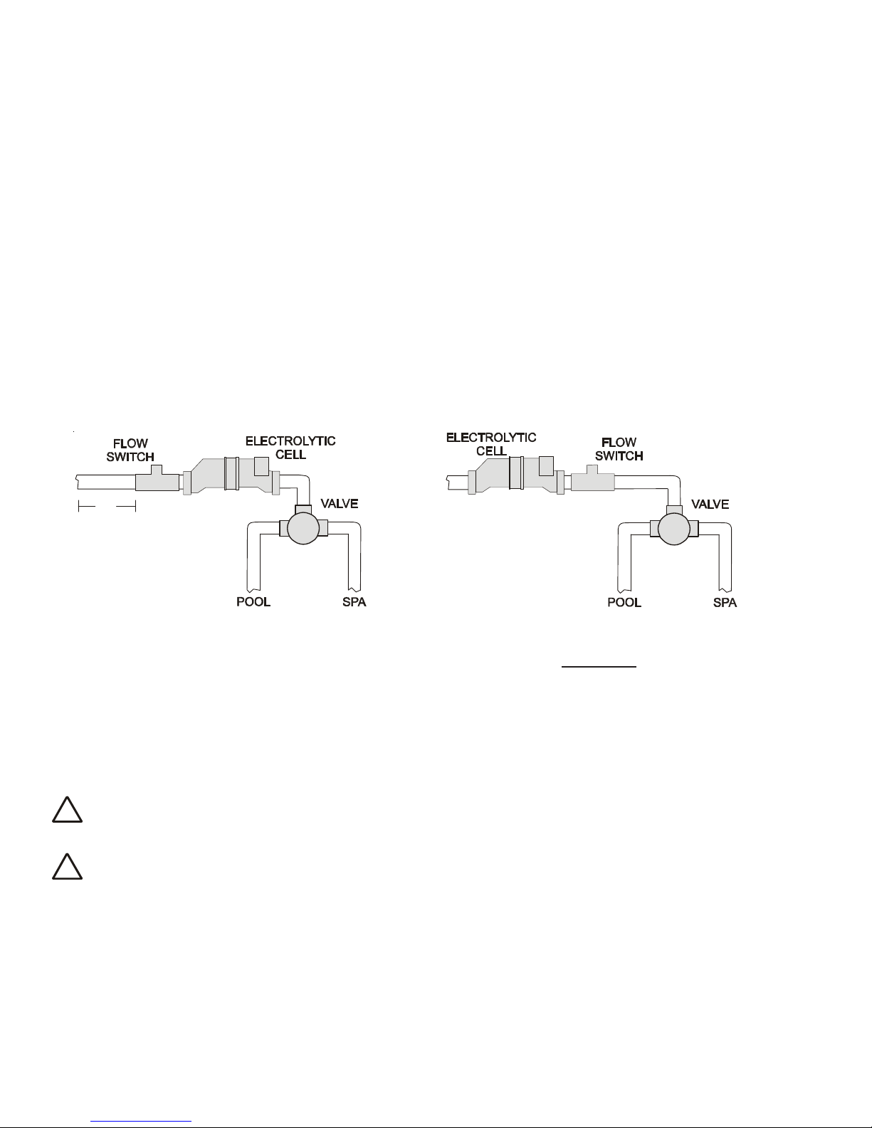
12”
min
Flow switch before cell
Flow switch after cell
Lights Config.
+ to view/change
Lights Function
Manual On/Off
Lights Name
Pool Light
Lights Relay
Standard
Push to access Lights options
Rotates between
Rotates between all available names
Toggle between Standard (default), Dimmer and VSP
Move to previous/next configuration menu
Move to next menu item
Move to next menu item or previous/next configuration menu
Move to next menu item or previous/next configuration menu
Lights Interlock
Disable
Lights Freeze
Disable
Toggle between Enabled and Disabled (default) Lights Freeze
Move to next menu item
Move to previous/next configuration menu
pH dispense, low speed, and group
pH dispense, low speed, and group
f
pH dispense, low speed, and group
or all functions except dimmer relay, super chlorinate
if filter pump is set to variable speed
and the relay type is set to standard
for manual on/off, countdown
timer and timeclock functions
Lights Group
Filter: Unaffected
Lights Group
Timer: None(Manual)
Options available depend on the function that is selected
Rotates between Manual On/Off (default),Countdown Timer and Timeclock
Move to previous/next menu item or next configuration menu
Move to next menu item
for group function only
for group function only
Lights Ext Input
Disabled
Toggle between Enabled and Disabled (default)
Move to previous/next configuration menu
Lights Pump Spd
Settings Menu
Move to previous/next configuration menu
be automatically suspended whenever the spa filter pump is turned on.
5. The chlorinator cell and flow switch must be installed in the heater return path. If spillover is enabled, then
the Pro Logic can chlorinate both the pool and spa (during spillover operation). Otherwise, the Pro Logic
will only chlorinate the pool when the spa does not control the heater(s) and the spa sanitization will have
to be handled manually.
6. If any water feature or pressure side cleaner boost pumps are used, be sure to enable the “interlock”
feature (see “Configuration Menu” for details) to ensure that the pumps operate only when the “Pool
Filter” pump is on and the system is in the “pool only” operating mode.
7. The plumbing diagram on page 10 is intended to be used as a general guideline and is not a complete
plumbing schematic for the pool.
8. When using the wireless spa-side remote control (AQL2-SS-RF), the “POOL” button will position the
valves for Pool mode and the “SPA” button will position the valves for Spillover mode.
Turbo Cell (choose proper model for your pool)
The Turbo Cell (used for chlorine generation) should be plumbed AFTER the filter and heater. If installed on a
pool/spa combination system, the cell should be plumbed BEFORE the pool/spa return valve in order to allow
proper chlorination of both the pool and the spa. Refer to plumbing diagram below:
The cell may be mounted vertically or horizontally, and water can move in either direction through the cell. Install
using the 2" unions provided in the P-KIT purchased separately. Tighten unions BY HAND for a watertight seal.
For systems with 1½“ plumbing use adaptors (provided by installer).
Flow Switch (supplied with P-KIT)
The flow switch must be plumbed in the same section of plumbing as the Turbo Cell. The flow switch is a safety
device that ensures that water is flowing through the cell before the Pro Logic starts to generate chlorine. Failure
to properly install the flow switch can result in explosive gases accumulating in the pool plumbing system.
IMPORTANT: There must be at least a 12" (30cm) straight pipe run before (upstream) the flow
switch. If the switch is plumbed after the cell, the cell can by counted as the 12" (30cm) of straight pipe.
IMPORTANT: To ensure proper operation, verify that the arrow on the flow switch points in the
direction of water flow
11
4. Electrical Wiring
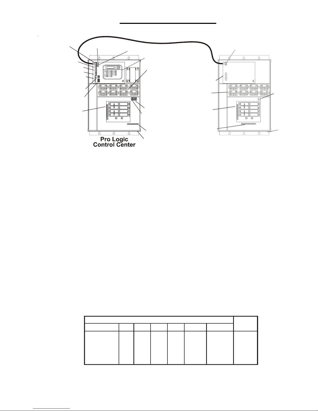
8 High Voltage Relays
for PS-8, PS-16
(4 relays for PS-4)
8 High
Voltage Relays
Control Power Input
Control Power
Input
Bonding Lug(s)
Bonding
Lug(s)
“Local” Display
Subpanel
Subpanel
Ground Bus Bar
pH Dispense
Output
Ground Bus Bar
L2 L2
N N
L1 L1
4 Valve Connectors
4 Valve Connectors
2 Heater Outputs
External Input Interlock
4 Temp
Sensor Inputs
To PS-16 Display/Keypad
Connector
Flow Switch
Connector
Cell Connector
Wireless Base
Receiver Connector
10
4 wire connection between PS-16 and -EXP
For use with
PS-16 only
Remote Display/Keypad
Connector
(AQL-PS-16 only)
AQL-CHEM
Connector
Torqu e
Cutler-Hammer
Murray
Siemens
Square D
Thomas & Betts
G.E.
Manufacturer
Single
Double
Quad
Twi n
GFCB
Filler Plates
BR
MP-T
QP
HOM
TB
THQL
BR
MP-T
QP
HOM
TB
THQL
BRD
MH-T
QT
HOMT
TBBD
BRD
MH-T
QT
HOMT
TBBQ
GFCB
MP-GT
QPF
HOM-GFI
GFB
THQL-GF
BRFP
LX100FP
QF3
HOMFP
FP-1C-TB
TFH
25lb-in
25lb-in
25lb-in
25lb-in
25lb-in
25lb-in
SUITABLE LISTED BREAKERS
9
8
7
Expansion Unit
The Pro Logic Control Center and PS-16 Expansion Unit require both high and low voltage connections. Low
voltage connections will be made to actuators, sensors, remote keypad, etc. High voltage connections will be
made to pumps, lights, etc., as well as providing direct input power to the Control Center. Always:
-Ensure that Power is disconnected prior to doing any wiring
-Follow all local and NEC (CEC if applicable) codes
-Use copper conductors only
Main Service (Power to the Circuit Breaker Subpanel)
The Pro Logic circuit breaker subpanel is rated for 100A service. Run properly rated conductors (L1, L2, N, and
ground) from the primary house electrical panel to the main power connections on the Pro Logic circuit breaker
base. The connection at the main house panel should be to a 240VAC circuit breaker rated at 100A maximum.
Grounding and Bonding
Connect a ground wire from the primary electrical panel to the Pro Logic ground bus bar. Also ground each piece
of high voltage (120 or 240VAC) equipment that is connected to the Pro Logic control relays or circuit breakers.
The Pro Logic should also be connected to the pool bonding system by an 8AWG (6AWG for Canada) wire. A
lug for bonding (2 for Canada) is provided on the outside/bottom of the Pro Logic enclosure.
Circuit Breaker Installation and Wiring
Circuit breakers are to be supplied by the installer. See the chart below for a list of suitable circuit breakers that
can be used. Follow the code and the circuit breaker manufacturer’s rating requirements regarding the size and
temperature rating for wiring. Note that some pool equipment may be required to be connected to ground fault
circuit breakers—check local and NEC (CEC) codes.
General Purpose Outlet
If desired, a duplex receptacle with weatherproof cover (supplied by installer) may be installed in the knockouts on
the lower right side of the Pro Logic enclosure. Per code, the receptacle should be a GFCI type. Alternatively,
connect a standard receptacle to a GFCB.
12
Tightening
 Loading...