

Hayward PowerFlo VS 300, SP1580X15VSP Owner's Manual
IS1580X15VSP Rev-A
PowerFlo VS
Owner’s Manual
™
300
Model SP1580X15VSP
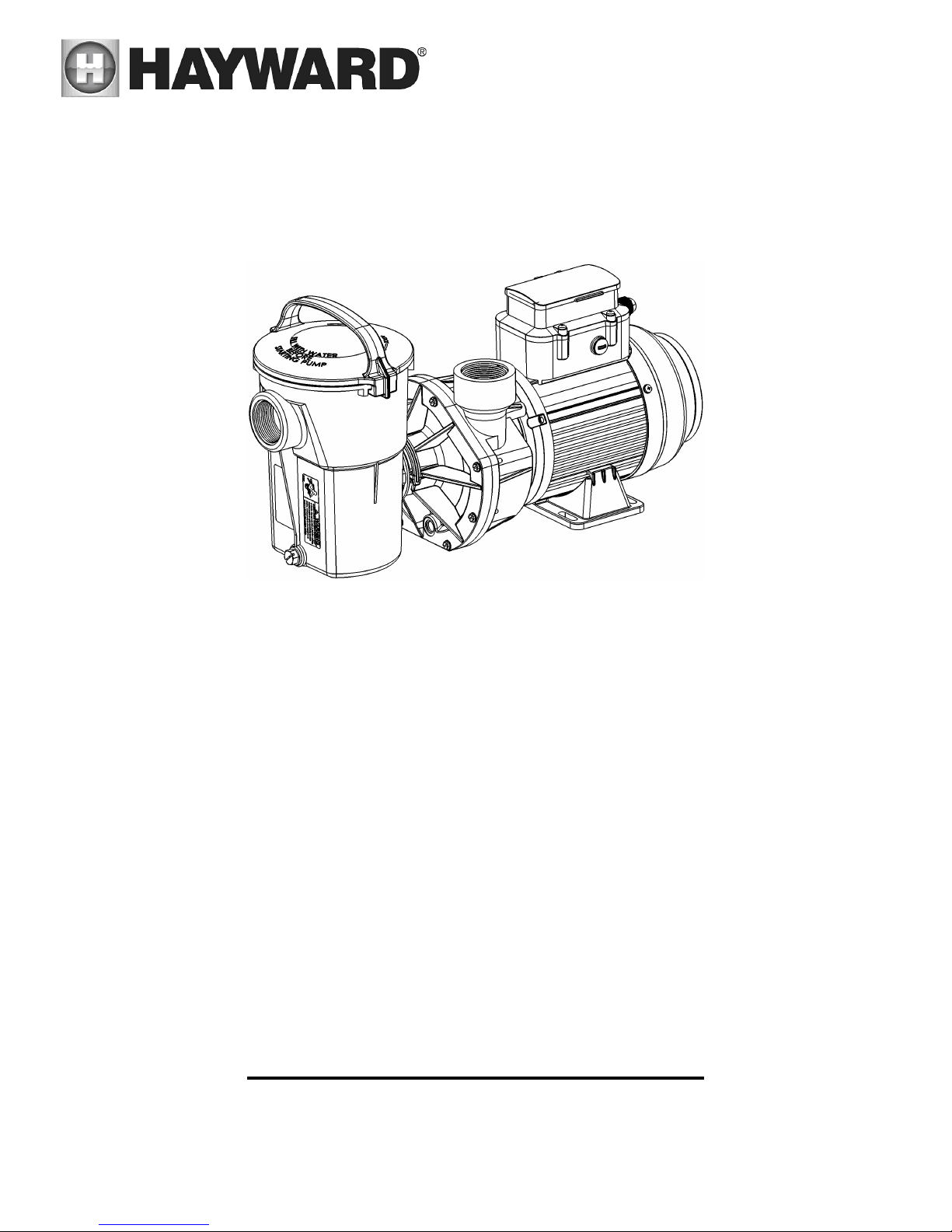
PowerFlo VS 300 Variable Speed Pump
Note: To prevent potential injury and to avoid unnecessary service calls, read this manual carefully and
completely.
SAVE THIS INSTRUCTION MANUAL
Hayward Pool Products
620 Division St, Elizabeth, NJ 07207
Phone: (908) 355-7995
www.hayward.com

Table of Contents
1. IMPORTANT SAFETY INSTRUCTIONS ................................................................................................................. 3
2. General Information ........................................................................................................................................ 6
2.1. Introduction 6
2.2. Primary Features 6
2.3. Product Dimensions 6
3. Installation and Wiring .................................................................................................................................... 7
3.1. Pump Location 7
3.2. Pump Mounting 7
3.3. Plumbing 7
3.4. Electrical 8
3.5. Electrical Specs 8
3.6. Voltage 8
3.7. Grounding and Bonding 8
3.8. Wiring 8
3.9. User Interface Summary 9
3.10. Starting the pump 9
3.11. Display Power Saving Mode 10
3.12. Stopping the Pump 10
3.13. To Change the Default Preset Speed Settings 10
3.14. Lockout Keypad Programming 10
3.15. Recover Factory Default Speed Settings 10
3.16. Fault Errors 10
3.17. Fault Error Code and Troubleshooting Chart 11
4. Maintenance .................................................................................................................................................11
5. Storage / Winterization ................................................................................................................................. 12
5.1. Storing Pump For Winterization 12
6. Shaft Seal Change Instructions ..................................................................................................................... 12
6.1. Shaft Seal Change Procedure 13
7. Replacement Parts ........................................................................................................................................ 14
7.1. Parts Diagram 14
7.2. Parts Listing 15
8. Troubleshooting ........................................................................................................................................... 16
8.1. General Problems 16
9. Product Registration ..................................................................................................................................... 18
10. Warranty ...................................................................................................................... ................................. 19
USE ONLY HAYWARD GENUINE REPLACEMENT PARTS
Page 2 of 20 PowerFlo VS Variable Speed Pump IS1580X15VSP Rev-A
1. IMPORTANT SAFETY INSTRUCTIONS
Before installing or servicing this electrical equipment, turn power supply OFF.
Basic safety precautions should always be followed, including the following: Failure to follow instructions may result in
injury.
This is the safety-alert symbol. When you see this symbol on your pump or in this manual, look for one of the
following signal words, and be alert to the potential for personal injury.
WARNING warns about hazards that could cause serious personal injury, death or major property damage
and if ignored presents a potential hazard.
CAUTION warns about hazards that will or can cause minor or moderate personal injury and/or property
damage and if ignored presents a potential hazard. It can also make consumers aware of actions that are
unpredictable and unsafe.
The NOTICE label indicates special instructions that are important but not related to hazards.
WARNING – READ AND FOLLOW ALL INSTRUCTIONS in this owner’s
manual and on the equipment. Failure to follow instructions can cause severe injury and/or death.
WARNING – This product should be installed and serviced only by a qualified professional.
CAUTION – All electrical wiring MUST be in conformance with all applicable local codes, regulations, and
the National Electric Code (NEC).
ATTENTION INSTALLER - THIS MANUAL CONTAINS IMPORTANT INFORMATION ABOUT THE INSTALLATION,
OPERATION, AND SAFE USE OF THIS VARIABLE SPEED PUMP THAT MUST BE FURNISHED TO THE END USER OF THIS
PRODUCT. FAILURE TO READ AND FOLLOW ALL INSTRUCTIONS COULD RESULT IN SERIOUS INJURY.
WARNING – To reduce risk of injury, do not permit children to use or climb on this product. Closely
supervise children at all times. Components such as the filtration system, pumps, and heaters must be positioned
to prevent children from using them as a means of access to the pool.
CAUTION – This pump is intended for use on permanently installed swimming pools and may also be used
with hot tubs and spas if so marked. Do NOT use with storable pools. A permanently installed pool is constructed in
or on the ground or in a building such that it cannot be readily disassembled for storage. A storable pool is
constructed so that it is capable of being readily disassembled for storage and reassembled to its original integrity.
Though this product is designed for outdoor use, it is strongly advised to protect the electrical components from the
weather. Select a well-drained area, one that will not flood when it rains. It requires free circulation of air for
cooling. Do not install in a damp or non-ventilated location. If installed within an outer enclosure or beneath the
skirt of a hot tub or spa, adequate ventilation and free circulation of air must be provided to prevent overheating of
the motor.
USE OF NON-HAYWARD REPLACEMENT PARTS VOIDS WARRANTY.
WARNING – Pool and spa components (seals, gaskets, etc.) have a finite life. All components should be
inspected frequently and replaced at least every ten years, or if found to be damaged, broken, cracked, missing, or
not securely attached.
USE ONLY HAYWARD GENUINE REPLACEMENT PARTS
Page 3 of 20 PowerFlo VS Variable Speed Pump IS1580X15VSP Rev-A
WARNING – Risk of Electric Shock. All electrical wiring MUST be in conformance with applicable local
codes, regulations, and the National Electric Code (NEC). Hazardous voltage can shock, burn, and cause death or
serious property damage. To reduce the risk of electric shock, do NOT use an extension cord to connect unit to
electric supply. Provide a properly located electrical receptacle. Before working on pump or motor, turn off power
supply to the pump.
WARNING – To reduce the risk of electric shock replace damaged wiring immediately. Locate conduit to
prevent abuse from lawn mowers, hedge trimmers and other equipment.
WARNING – Electrical ground all electrical equipment before connecting to electrical power supply. Failure to ground
all electrical equipment can cause serious or fatal electrical shock hazard.
WARNING – Do NOT ground to a gas supply line.
WARNING – To avoid dangerous or fatal electrical shock, TURN OFF POWER to all electrical equipment before working.
WARNING – Risk of Electric Shock. In accordance with the National Electric Code (NEC), connect only to a
branch circuit protected by a ground-fault circuit-interrupter (GFCI). Contact a qualified electrician if you cannot
verify that the circuit is protected by a GFCI. The unit must be connected only to a supply circuit that is protected by
a ground-fault circuit-interrupter (GFCI). Such a GFCI should be provided by the installer and should be tested on a
routine basis. To test the GFCI, push the test circuit button. The GFCI should interrupt power. Push the reset button.
Power should be restored. If the GFCI fails to operate in this manner, the GFCI is defective. If the GFCI interrupts
power to the pump without the test button being pushed, a ground current is flowing, indicating the possibility of an
electric shock. Do not use this pump. Disconnect the pump and have the problem corrected by a qualified service
representative before using.
WARNING – Failure to bond pump to pool structure will increase risk for electrocution and could result in
injury or death. To reduce the risk of electric shock, see installation instructions and consult a professional
electrician on how to bond pump. Also, contact a licensed electrician for information on local electrical codes for
bonding requirements.
Notes to electrician: Use a solid copper conductor, size 8 or larger. Run a continuous wire from external bonding lug
to reinforcing rod or mesh. Connect a No. 8 AWG (8.4 mm
wire to the pressure wire connector provided on the pump housing and to all metal parts of swimming pool, spa, or
hot tub, and to all electrical equipment, metal piping (except gas piping), and conduit within 5 ft. (1.5 m) of inside
walls of swimming pool, spa, or hot tub. IMPORTANT - Reference NEC codes for all wiring standards including, but
not limited to, grounding, bonding and other general wiring procedures.
WARNING – Suction Entrapment Hazard. Suction in suction outlets and/or suction outlet covers, which are
damaged, broken, cracked, missing, or unsecured cause severe injury and/or death due to the following entrapment
hazards (symbols complements of APSP):
Hair Entrapment - Hair can become entangled in suction outlet cover.
Limb Entrapment - A limb inserted into an opening of a suction outlet sump or suction outlet cover that is damaged,
broken, cracked, missing, or not securely attached can result in a mechanical bind or swelling of the limb.
Body Suction Entrapment - A differential pressure applied to a large portion of the body or limbs can result in an
entrapment.
Evisceration/ Disembowelment - A negative pressure applied directly to the intestines through an unprotected
suction outlet sump or suction outlet cover which is damaged, broken, cracked, missing, or unsecured can result in
evisceration/disembowelment.
2
) [No. 6 AWG (13.3 mm2) for Canada] solid copper bonding
Mechanical Entrapment - There is potential for jewelry, swimsuits, hair decorations, fingers, toes, or knuckles to be
caught in an opening of a suction outlet cover resulting in mechanical entrapment.
USE ONLY HAYWARD GENUINE REPLACEMENT PARTS
Page 4 of 20 PowerFlo VS Variable Speed Pump IS1580X15VSP Rev-A
WARNING – To Reduce the risk of Entrapment Hazards:
When outlets are small enough to be blocked by a person, a minimum of two functioning suction outlets per
pump must be installed. Suction outlets in the same plane (i.e. floor or wall), must be installed a minimum of
three feet (3’) [0.91 meter] apart, as measured from near point to near point.
Dual suction fittings shall be placed in such locations and distances to avoid “dual blockage” by a user.
Dual suction fittings shall not be located on seating areas or on the backrest for such seating areas.
The maximum system flow rate shall not exceed the flow rating as listed on the suction outlet cover.
Never use pool or spa if any suction outlet is damaged, broken, cracked, missing, or not securely attached.
Replace damaged, broken, cracked, missing, or not securely attached suction outlet components
immediately.
In addition to two or more suction outlets per pump installed in accordance with latest APSP standards and
CPSC guidelines, follow all national, state, and local codes applicable.
Installation of a vacuum release or vent system, which relieves entrapping suction, is recommended.
WARNING – Hazardous Pressure. Pool and spa water circulation systems operate under hazardous
pressure during start-up, normal operation, and after pump shut-off. Stand clear of circulation system equipment
during pump start-up. Failure to follow safety and operation instructions could result in violent separation of the
pump housing and cover due to pressure in the system, which could cause property damage, severe personal injury,
or death. Before servicing pool and spa water circulation system, all system and pump controls must be in off
position and filter manual air relief valve must be in open position. Before starting pump, all system valves must be
set in a position to allow system water to return back to the pool. Do not change filter control valve position while
pump is running. Before starting pump, fully open filter manual air relief valve. Do not close filter manual air relief
valve until a steady stream of water (not air or air and water mix) is discharged from the valve. All suction and
discharge valves MUST be OPEN when starting the circulation system. Failure to do so could result in severe
personal injury and/or property damage.
WARNING – Separation Hazard. Failure to follow safety and operation instructions could result in violent
separation of pump components. Strainer cover must be properly secured to pump housing with strainer cover lock
ring. Before servicing pool and spa circulation system, all system and pump controls must be in off position and
filter manual air relief valve must be in open position. Do not operate pool and spa circulation system if a system
component is not assembled properly, damaged, or missing. Do not operate pool and spa circulation system unless
filter manual air relief valve body is in locked position in filter upper body. All suction and discharge valves MUST be
OPEN when starting the circulation system. Failure to do so could result in personal injury and/or property damage.
WARNING – Failure to remove pressure test plugs and/or plugs used in winterization of the pool/spa from
the suction outlets can result in an increase potential for suction entrapment as described above.
WARNING – Failure to keep suction outlet components clear of debris, such as leaves, dirt, hair, paper and
other material can result in an increase potential for suction entrapment as described above.
WARNING – Never operate the circulation system at more than 30 PSI maximum.
WARNING – Never change the filter control valve position while the pump is running.
WARNING – Fire and burn hazard. Motors operate at high temperatures and if they are not properly isolated
from any flammable structures or foreign debris they can cause fires, which may cause severe personal injury or
death. It is also necessary to allow the motor to cool for at least 20 minutes prior to maintenance to minimize the
risk for burns.
WARNING – Failure to install according to defined instructions may result in severe personal injury or
death.
SAVE THESE INSTRUCTIONS
USE ONLY HAYWARD GENUINE REPLACEMENT PARTS
Page 5 of 20 PowerFlo VS Variable Speed Pump IS1580X15VSP Rev-A
2. General Information
2.1. Introduction
This manual contains information for the proper installation and operation of the Hayward PowerFlo VS 300 Variable
Speed Pump. The instructions in this manual MUST be followed precisely.
2.2. Primary Features
Totally enclosed, permanent magnet motor
Advanced hydraulic design
Programmable with up to 3 custom speeds
For enhanced pool management, can be controlled by Hayward or third party pool and spa control platforms,
without the need for additional accessories
Motor drive includes built-in protection for high temperatures and voltage fluctuations.
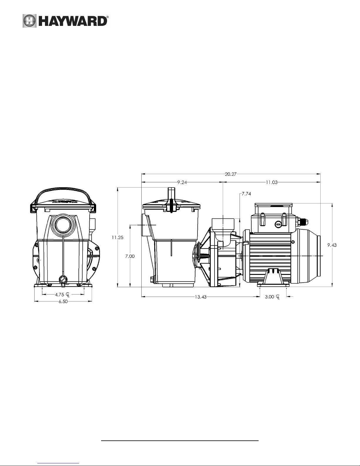
2.3. Product Dimensions
USE ONLY HAYWARD GENUINE REPLACEMENT PARTS
Page 6 of 20 PowerFlo VS Variable Speed Pump IS1580X15VSP Rev-A
 Loading...