

Hayward Pool Vac Classic, Pool Vac XL, Navigator Pro Owner's Manual
P/N K540AD-Rev E
Owner’s Manual
Hayward Pool Products
620 Division Street Elizabeth, NJ 07207
Phone (908) 351-5400
www.hayward-pool.com
Pool Vac XL
®
Navigator Pro
®
Pool Vac Classic

Pool Vac XL
Navigator Pro
Pool Vac
Classic
OWNER’S MANUAL
Congratulations on your purchase of your Hayward automatic suction pool cleaning system
from Hayward. Your Cleaner is the smart, efficient way to clean your in-ground pool.
Hayward Turbine Cleaners are powered by your pool’s filter system and are designed to
work well with most systems. Therefore the performance of the Cleaner in your pool will
be relative to that power source. Because the operation and performance of the Cleaner
are system reliant, there is a remote possibility that a “service call” may be necessary to
complete the proper installation of your Cleaner. Because this is an installation related
call, it will be at the consumer’s expense. Also, one or more of the accessories designed
for the Cleaner, including additional hose sections (if needed), might be applicable to
your installation. Consult your Hayward dealer for the price and availability. For Technical
Assistance, call Hayward at 908-355-7995 (USA only).
Record the following information for your convienience
1) Purchase Date
2) Serial Number
For Your Records
Note
Turbine Suction Cleaner
Hayward Turbine Cleaners should not be used to clean the pool for spring start-up
unless the conditions noted in Step 1 are met. On those occasions, where your pool is
subjected to an abnormal debris load, maintenance steps should be taken to return the
pool to “pre-installations” condition.
LIMITED
WARRANTY
LIMITED
WARRANTY

1
Installation
INSTALLING YOUR HAYWARD CLEANER IS SIMPLE...
To prepare your pool for installation, please follow the easy steps listed below. After
reading these instructions, the “How To” installation DVD (included with Pool Vac XL &
Navigator Pro only) will walk you through the installation step-by-step, and it will also give
you some maintenance and trouble-shooting hints. These instructions apply to all Hayward
Turbine Cleaner models.
Step 1
Check the pool and remove any large objects that might interfere with the cleaner’s
operation. Check to see that the water level is at the recommended level. Check the water
chemistry. Make sure that the water is properly balanced and that the pool is free from
algae. Algae can adversely affect the operation of the Cleaner and its performance.
Step 2
Clean or backwash the filter, and clean the hair and lint prior to installing the Cleaner.
Following the installation of your Cleaner, clean the system at regular intervals according to
individual pool conditions.
Step 3
There are connector hoses (9 with PV XL & NAV PRO, 7 with PV Classic) and one leader
hose with a hose cuff are included. The hose cuff has a red sticker attached to it that reads
“REMOVE LABEL AND CONNECT TO CLEANER”.
Connect the exclusive Hayward hose sections together by pushing and twisting the tapered
male connector end of each hose firmly into the open female end of the adjacent hose (see
Figure 1). Depending on the size and shape of your pool, all hose sections might not be
used. However, the leader hose must be used or your Cleaner will not operate properly. It is
not necessary to “Bottom Out” the connections, but they must be tight enough to prevent
any air leaks. Wetting the hose ends will make it easier to connect the hose sections.
2
Step 4
The hose should reach from the skimmer or Hayward Vac Lock® to the furthest point in
the pool, plus two (2) extra hose sections. (The length of each hose section is four feet.)
This extra length is absolutely necessary for proper operation of your Hayward Cleaner. If
the hose is not long enough, it will be necessary to purchase additional hose sections from
your Hayward dealer. The hose length supplied has been determined to be sufficient for
the class and size of pools for which each type of cleaner is sold – 40 feet for PV XL & NAV
Pro, 32 feet for PV Classic. If your hose requirement is more than this, you must obtain
additional hose sections for your cleaner to work properly. After the correct hose length has
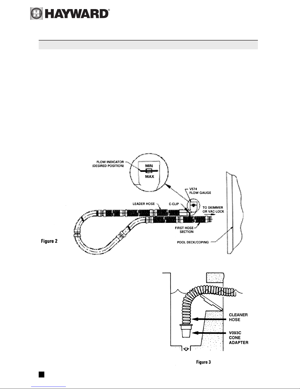
been assembled, fill hose completely with water. Insert Flow Gauge into the leader hose,
then attach the C-Clip of the gauge onto the first hose section. Make sure the Flow Gauge
is under water. (see Figure 2)
Step 5
Turn the filter system on and allow it to run long
enough to eliminate any air in the system. Connect the
V093C Skimmer Cone adapter to the tapered male end of
the vacuum hose if you are connecting the hose to your
skimmer. Then, insert the cone into the suction port of
the skimmer (see Figure 3) or, if you are using a
Hayward Vac Lock, insert the hose end directly
into the Vac Lock without using the cone. (Refer
to Important Tips for more specific skimmer
information.)
Installation
INSTALLING YOUR HAYWARD CLEANER IS SIMPLE...

3
Step 6
Check the water flow reading on the Flow Gauge. (Refer to Step 4, Figure 2). The black disk
should be in the box between the “MIN” and “MAX” markings. If the setting is higher than
required with the black disk outside of the box on the “MAX” side and you have connected
your hose to the skimmer, it will be necessary to reduce the vacuum/water flow by using
a valve or valves in the filter system, or the Hayward V094 Regulator Valve or an optional
Hayward Automatic Skimmer Vacuum Plate designed to adjust vacuum/water flow. To install
the V094 Regulator Valve, turn the filter system off, remove the hose from the V093C
Skimmer Cone, and after closing the Regulator Valve (Rotate the blue collar clockwise until
tight), insert the Valve into the Skimmer Cone, and insert the hose end into the Valve (see
Figure 4).
Turn the filter system on and allow it to run long enough to eliminate any air in the system.
Turn the blue collar counter clockwise until proper reading appears on the gauge. If a
Hayward Skimmer Vacuum Plate is to be used, follow the installation instructions included
with the Skimmer Vacuum Plate.
Installation
INSTALLING YOUR HAYWARD CLEANER IS SIMPLE...

4
Note
The V094 Regulator Valve and the Hayward Skimmer Vacuum Plate can only be used to
LOWER an initial vacuum reading that is TOO HIGH. The Regulator Valve and the Skimmer
Vacuum Plate cannot be used to INCREASE the initial vacuum reading. An initial reading
that is too low to meet the water flow setting necessary to operate the cleaner is indicative
of a system problem, and not a problem with the cleaner.
Contact your Authorized Hayward Dealer for assistance.
If you have connected your hose to the Hayward Vac Lock, it will be necessary to adjust
the vacuum/water flow using the 3-way valve at the filter system. The handle on the valve
should be turned so that the Flow Gauge which is installed in the Cleaner hose reads
properly (refer to Figure 2). After the 3-way valve has been properly adjusted, the 3-way
valve should be marked so that the water flow can be adjusted by referring to the valve
handle mark, rather than reinstalling the Flow Gauge in the hose each time an adjustment
is necessary.
Step 7
Remove the Flow Gauge from the hose and keep it handy. You will want to use the Flow
Gauge to check the Cleaner’s operation from time to time if the Cleaner is connected to
your skimmer. If you are using a Hayward Vac Lock, the Flow Gauge will only be necessary
if you neglect to mark the valve gauge, or if replacement of the valve gauge is necessary.
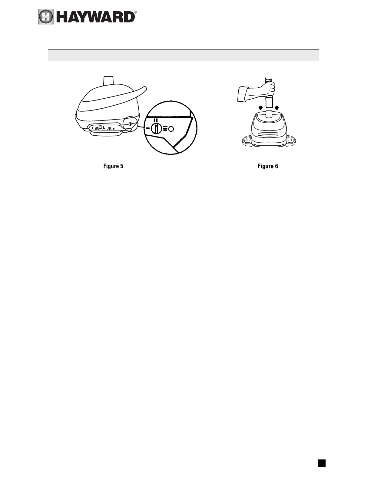
Step 8
Check the rear flap adjuster dial at the left rear of the Cleaner. It should be set at position
number II which is the middle position (see Figure 5). Submerge the Cleaner into the water
to remove all of the entrapped air. When escaping air bubbles cease, you are ready to
connect the hose.
Connect the hose cuff of the leader hose to the Cleaner and submerge the hose to remove
all air as when vacuuming the pool with a standard hand-vacuum (see Figure 6).
Do not use the return line/inlet water to “sink” the Cleaner hose, as this will force air into
the cleaner head, and possibly cause performance problems.
Installation
INSTALLING YOUR HAYWARD CLEANER IS SIMPLE...
5
Step 9
Observe your Cleaner in operation, and make sure that the return line flow is not affecting
the Cleaner’s programmed steering and preventing the Cleaner from covering the entire
pool. If the cleaner hose is being pushed across the surface of the pool, it will be necessary
to redirect the return line water flow downward. This is to allow the Cleaner to move its
programmed cleaning pattern.
Step 10
Observing the Cleaner in operation, it should move about the pool without spending an
excessive amount of time against the steps or other obstructions (vertical walls, ladders,
etc.) If the Cleaner seems to get “hung up,” turn the rear flap adjuster to position I (see
Figure 5).
Step 11
Your Cleaner will climb the vertical walls in concrete and fiberglass swimming pools if there
is at least a seven inch (7") radius where the walls and floor meet. The Cleaner’s wall
climbing is governed by the programmed steering and therefore it will not climb the wall
each time it comes in contact with a wall. When the Cleaner does start up a wall, it will not
always go all the way up the wall. If the Cleaner does not seem to be “sticking” to the wall,
turn the rear flap adjuster to position III (see Figure 5). If the Cleaner climbs to the water’s
surface and sucks air, turn the rear flap adjuster to Position I (see Figure 5). If the cleaner
continues to climb too high, reduce the water flow until proper operation is achieved.
Approximately ninety percent (90%) of the dirt in a concrete pool will be on the floor of
the pool. Approximately ten percent (10%) of the dirt will be on the walls. Your Cleaner will
spend its cleaning time accordingly.
Installation
INSTALLING YOUR HAYWARD CLEANER IS SIMPLE...
6
Pool Vac XL/Navigator Pro
In one piece fiberglass pools there is very little dirt on the walls, but your Cleaner will still
climb the walls. Due to the shape (severe angles) of most in-ground vinyl liner pools, your
Cleaner’s cleaning is confined to the bottom (both shallow and deep) and the hopper sides.
Hayward Turbine Cleaners do not climb the vertical walls of in-ground or on-ground vinyl
liner pools. However, normal dirt and debris do not adhere to these walls.
1. Skimmers come in many configurations and cannot all be described here. Three basic
types are discussed however.
Some skimmers have two (2) holes in the bottom. There might be a valve, float or cover
over the holes. Remove everything in the skimmer, exposing the holes. The rear hole is
usually the suction port. In some cases it will be necessary to use the V094 Regulator Valve
to control water flow through the Cleaner (see Figure 4).
Some skimmers have only one hole in the bottom. This suction port is usually controlled by a
valve at the filter system and most likely will not need a V094 Regulator Valve (see Figure 3).
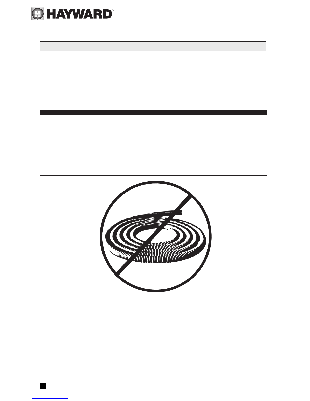
DO NOT COIL HOSE
When storing your cleaner the hose sections must be stored straight, not coiled. A coiled
hose will create a memory in the hose that will impede the Cleaner’s ability to move
properly in your pool. Coiled hoses are not covered under the Hayward warranty. When
removing the Cleaner from your pool, be sure to grasp the cleaner by its handle, not by its
hose, otherwise the Cleaner might be damaged should the hose disconnect from the cleaner.
IMPORTANT TIPS
Turbine Suction Cleaners
 Loading...