

Hayward PL-PS-4, PL-PS-8-V, PL-PS-8, PL-PS-16, PL-PS-16-V Operation Manual

Pro Logic
Automation and Chlorination
PL-PS-4 PL-PS-8-V
PL-PS-8 PL-PS-16-V
PL-PS-16
Operation Manual
for models
www.hayward.com

IMPORTANT SAFETY INSTRUCTIONS
!
!
!
When using this electrical equipment, basic safety precautions should always
be followed, including the following:
•
•
•
•
• A green colored terminal marked “Grounding” is located inside the wiring
• One bonding lug for US models (two for Canadian models) is provided on the
READ AND FOLLOW ALL INSTRUCTIONS
WARNING: Disconnect all AC power during installation.
WARNING: Water in excess of 100 degrees Fahrenheit may be
hazardous to your health.
WARNING: To reduce the risk of injury, do not permit children to
use this product unless they are closely supervised at all times.
compartment. To reduce the risk of electric shock, this terminal must be
connected to the grounding means provided in the electric supply service
panel with a continuous copper wire equivalent in size to the circuit
conductors supplying the equipment.
external surface. To reduce the risk of electric shock, connect the local
common bonding grid in the area of the swimming pool, spa, or hot tub to
these terminals with an insulated or bare copper conductor not smaller than 8
AWG US / 6 AWG Canada.
• All field installed metal components such as rails, ladders, drains, or other
similar hardware within 3 meters of the pool, spa or hot tub shall be bonded
to the equipment grounding bus with copper conductors not smaller than
8 AWG US / 6 AWG Canada.
• SAVE THESE INSTRUCTIONS

Table of Contents
System Overview Block Diagram....................................................................... 1
Automation............................................................................. 1
Chlorination............................................................................ 2
Default Display...................................................................... 2
Manual System Output Names........................................................................ 3
Operation Filter Pump............................................................................. 3
Lights and Aux Outputs.......................................................... 4
Pool/Spa Valves..................................................................... 4
Heaters................................................................................... 5
System Off............................................................................. 5
Service................................................................................... 5
Automatic System Using the Programming Buttons.......................................... 6
Operation Programming Menu Flow Chart........................................... 7
(Programming) Settings Menu........................................................................ 8
Timers Menu.......................................................................... 12
Group Function...................................................................... 15
Configuration Menu............................................................... 17
Maintenance Menu............................................................... 32
Quick “How To” Operate the Spa - Manually.................................................. 33
Guide Operate the Spa - Automatically.......................................... 33
Set the Heater Temperature................................................. 33
Set the Chlorinator Output ................................................... 33
Start/Stop Superchlorination................................................ 34
Program a Timeclock............................................................ 34
Program a Countdown Timer............................................... 34
Enter/Exit Service Mode....................................................... 34
Chlorinator Operation/ Saturation Index..................................................................... 35
Water Chemistry Salt Level................................................................................ 36
Type of Salt............................................................................ 36
How to Add or Remove Salt................................................. 36
System Maintenance Servicing and Cleaning the Chlorinator Cell....................... 39
Winterizing.............................................................................. 39
Spring Startup........................................................................ 39
Troubleshooting & Service Mode ....................................................................... 40
Diagnostic Information Check System Indicator........................................................ 40
Diagnostic Menu................................................................... 42
Warranty Pro Logic Warranty................................................................ 48

System Overview
Water
External
Input
Air
Spa
(for dual equip)
Solar
Chlorinator
Flow Switch
240 VAC
Power
240 VAC
Filter Pump
Lights
Aux
Aux (8)
Return Valves
General Purpose
Val v e s (2 )
General Purpose
Val ve s (4 )
Heaters (2)
Circuit Breaker
Subpanel
Circuit Breaker
Subpanel
Main Display
Keypad
Optional Wired
Remote D isplay
Keypad
(maximum of three)
Optional Wireless
Remote Display
Keypad
Optional Wireless
Spaside Remote
Temperature
Sensors
Relays
Relays
A
A
INPUT
OUTPUT
OUTPUT
Optional
Receiver
LDLINE
CONTROLS INC.
G
POOL SPA
ON OFF
ON OFF
ON OFF
ON OFF
ON OFF
VALVES
FILTER
HEATER
LIGHTS
AUX1
AUX2
(2 for PS-4)
(used with PS-16 only)
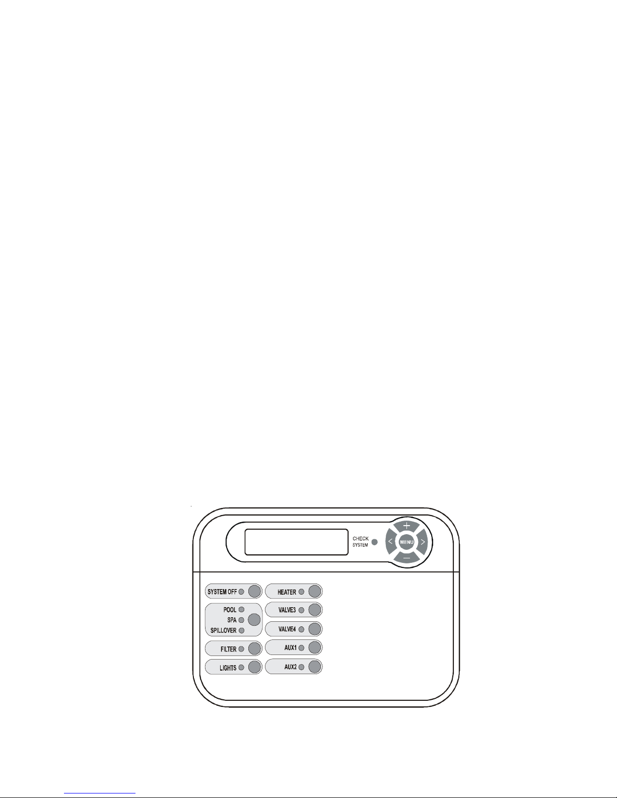
The Hayward Pro Logic is a multifunction pool controller used to fully manage your pool/spa system. The Pro
Logic can control pumps, valves, lighting, heaters, and chlorination. Although the Pro Logic is easy to use, it is
important to completely read through this operating manual before attempting to operate the control.
Wireless Base
PS-4 (-8, -16) MAIN UNIT
Pool/Spa Suction &
Chlorinator Cell
(6 for PS-8, PS-16)
120/240V
24V Valve
ctuators
NOTE: This manual assumes that the Pro Logic has been wired and configured according to the Installation
Manual. Aspects of the Pro Logic that pertain to system setup are not covered in this manual.
Automation
The PL-PS-4 (-8, -16) can control up to 4 (8, 16) high voltage (120/240V) pieces of equipment, up to 4 (8 for the
PS-16) automatic valve actuators, and 2 conventional heaters plus a solar heater. Both manual and automatic
(programmed) operation are available. All of the control functions can be programmed at a display/keypad which
is part of the main unit (typically located near the pool equipment) or at one or more remote display/keypads.
EXPANSION UNIT
Power
120/240V
24V Valve
ctuators
1
Chlorination
When the chlorinator function is enabled (requires a chlorinator cell and P-KIT sold separately), the Pro Logic is
also an automatic chlorine generation system for pool and/or spa sanitization. If enabled (see Configuration Menu),
this operation requires a low concentration of salt (sodium chloride) in the pool/spa water. The Pro Logic automatically converts the salt into free chlorine which kills bacteria and algae in the pool/spa. Chlorine will revert back
to sodium chloride after killing bacteria. These reactions will continuously recycle, virtually eliminating the need to
add sanitizing chemicals to your pool/spa. The only time you may need to add more salt to the pool/spa is when
water is replenished due to backwashing, draining, or splashing (not evaporation).
The Pro Logic is designed to handle the purification needs of most residential swimming pools up to 40,000 gallons
(150,000 liters), or the needs of most commercial pools up to 25,000 gallons (95,000 liters). Check local codes
for other restrictions. The actual amount of chlorination required to properly sanitize a pool varies due to bather
load, rainfall, temperature, and the pool’s cleanliness.
For pools larger than 40,000 gallons, the Pro Logic can control one or more Hayward Aqua Rite chlorinators to
supplement chlorine production.
NOTE: Before installing this product as part of a saline water purification system in a pool or spa using natural
stone for coping or for immediately adjacent patios/decking, a qualified stone installation specialist should be
consulted regarding the appropriate type, installation, sealant (if any) and maintenance of stone used around a
saline pool with electronic chlorine generator in your particular location and circumstances.
NOTE: The use of dry acid (sodium bisulfate) to adjust pool pH is discouraged especially in arid regions where
pool water is subject to excessive evaporation and is not commonly diluted with fresh water. Dry acid can cause a
buildup of by-products that can damage your chlorinator cell.
Default Display
Turn power on at the main panel and turn the Pro Logic control power circuit breaker on. The keypad will show
the default display. The default display alternates between the day/time, air and pool (or spa) temperature, pool/
spa sanitizer setting, and salt level. Under certain circumstances, additional displays may be added to the default
menu to inform you about system operation. Refer to the Programming Menu Flowchart on page 7 to view all
possible displays. The Pro Logic will automatically scroll through all of the available default menu displays or you
can press “<” or “>” to manually scroll.
Optional Remote Display/keypad shown--the display keypad on the
main control unit will have a “Service” button in the upper left
corner instead of the “System Off” button.
2
Manual System Operation
(On/Off)
Display
Valve4 or Heater2
(See Configuration Menu)
System Off (remote displays)
or
Service (main unit display)
VSP Speed/Power
Filter
± to view
No function
Move to previous/next menu item
Move to previous/next menu item
Main Software
Revision 4.00
remote-08 r3.10
Revision 1.10
RF Base Software
r1.20 ID:1234
Pool Filter VSC
Software r1.00
Software r1.00
6B Spa Software
Remote A r1.00
Pool Filter Drive
Software r1.00
Pool Filter Display
Software r1.00
Remote B r1.00
CL Module Software
Revision 1.00
CL Light Software
+ to view
CL LT1 Software
App:1.00 BL:1.02
No function
No function
No function
No function
No function
No function
No function
No function
No function
No function
No function
Press to view the software revisions of detected lights
Press to view the software revisions of detected lights
Move to previous/next menu item
Move to previous/next menu item
Move to previous/next menu item
Move to previous/next menu item
Move to previous/next menu item
Move to previous/next menu item
Move to previous/next menu item
Move to previous/next menu item
Move to previous/next menu item
Move to previous/next menu item
Move to previous/next menu item
Move to previous/next menu item
Move to previous/next ColorLogic 4.0 light/menu item
Chemistry Sense
Software r1.00
VSP Software
± to view
No function
Move to previous/next menu item
Move to previous/next menu item
if TriStar VSPs are detected
if TriStar VSPs are detected
if EcoStar VSPs are detected
if EcoStar VSPs are detected
While the main objective of the Pro Logic is to automate the operation of your pool/spa system, there may be
certain times when you want to override the automatic operation and control the equipment manually. To operate
the pool equipment manually while keeping the automation active, perform the following procedures. Note that if
you turn a relay on manually, it will remain on until either you turn it off manually, or the next time the programmed
automatic operation would normally turn that relay off. Example: the filter pump is programmed to run from 9:00A
to 5:00P daily. If you turn the filter pump on manually at 8:00PM, it will run continuously until the next day at
5:00PM at which time it will turn off and follow the normal program from then on. Manually turning off a relay
works in a similar fashion.
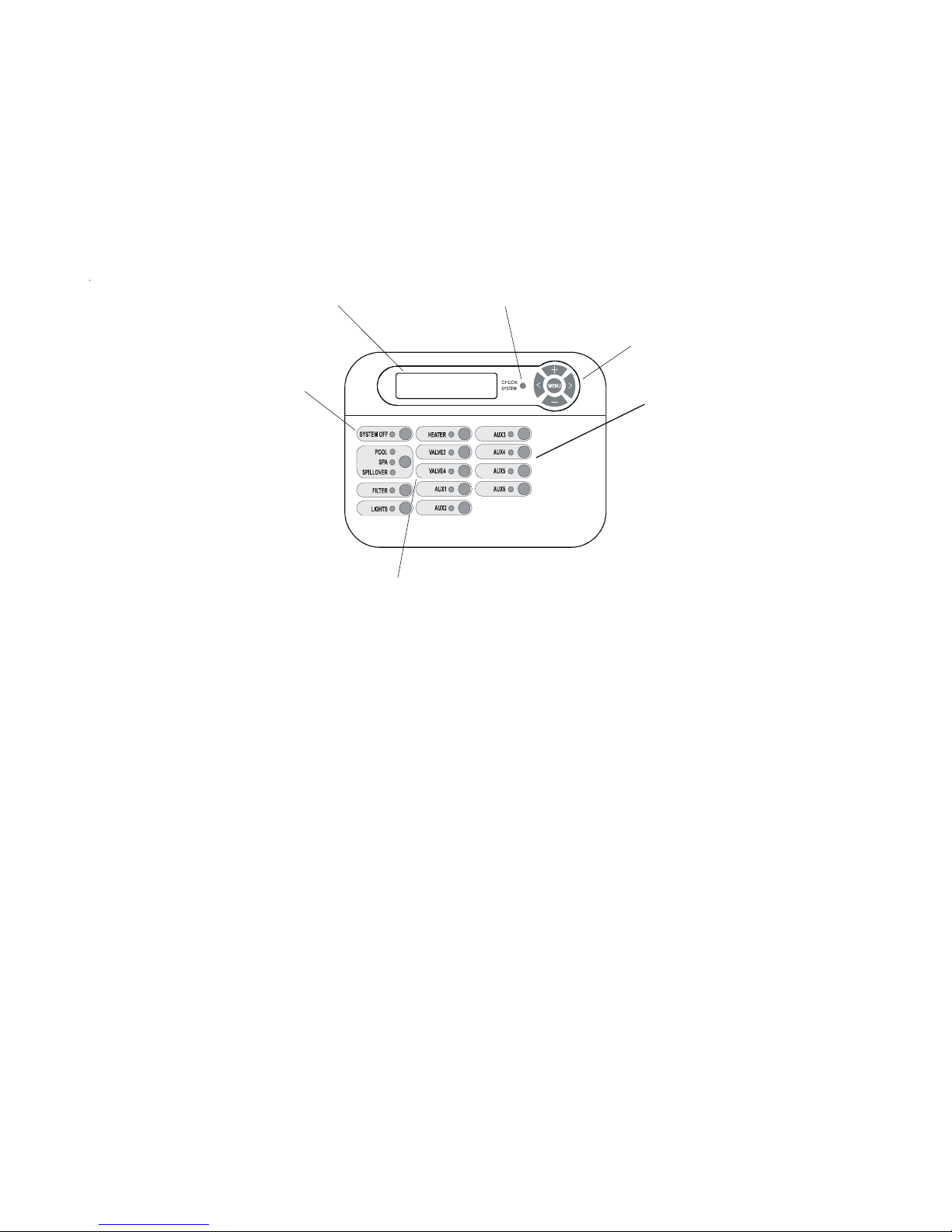
Check System LED
Menu and Navigation Buttons
Aux1 - Aux6
Output Names
The Pro Logic is shipped from the factory with each output labeled with a generic name (e.g. AUX1, VALVE3,
etc.). One of the features in the software (see Configuration Menu, page 17) is that each output can be assigned a
new name that is more descriptive of the equipment being controlled. This makes it much easier to operate all of the
equipment on your pool without having to memorize what each output controls. Insert name labels are also provided to be placed next to each display pushbutton. Since there is no way to know how your particular system is
configured, this manual will use the original generic names for each output.
Pool Filter Pump
The pool filter pump can be manually operated whether in Standard (single pump) or Dual Equipment (separate
pumps for both pool and spa) mode. When in Standard mode, the display will refer to the pool filter pump as
“FILTER”. When in Dual Equipment mode, the display will read “POOL FILTER”.
Single Speed Filter Pump: If the pump is currently off, press the “FILTER” button to turn on the pump. Pressing
the “FILTER” button again will turn off the pump. However, if there is a heater in the system, and it is operating,
and the “Heater Cooldown” feature is enabled (Configuration Menu) then: when you press the “FILTER” button
to turn off the filter, only the heater will turn off, the “FILTER” LED will flash and the display will indicate “Heater
Cooldown”. At this point the filter pump will automatically turn off after 5 minutes of heater cooldown operation.
If you want to override the heater cooldown, simply press the “FILTER” button again to turn off the filter pump.
3

Two Speed Filter Pump: If the pump is currently off, simply press the “FILTER” button to turn on high speed
operation of the filter pump. The “Filter” LED will illuminate continuously. Pressing the “FILTER” button again will
switch to low speed operation and the “FILTER” LED will flash. Note that if the pump has been off for more than
30 seconds, it will run at high speed for 3 minutes regardless of selection. This high speed operation helps allow the
pump to prime and establish normal water flow.
Variable Speed Filter Pump: If the pump is currently off, press the “FILTER” button to turn the filter pump on to
the last speed (1, 2, 3, or 4) that was used. A temporary display is generated indicating the current speed selection
(Filter On:Spd 1). Pushing the “+” or “-” button changes the speed selection. If the pump has been off for more
than 30 seconds, it will run at the highest speed for 3 minutes regardless of selection. This high speed operation
helps allow the pump to prime and establish normal water flow.
Freeze Protection: This function protects the pool, plumbing, and equipment against freeze damage. If Freeze
Protection is enabled and the AIR temperature sensor falls below the preset freeze protection temperature (see
Filter Configuration), the Pro Logic will turn on the filter pump to circulate the water.
Spa Filter Pump (when using Dual Equipment)
Single Speed Filter Pump: If the pump is currently off, press the “AUX1” button to turn on the pump. Pressing
the “AUX1” button again will turn off the pump. However, if there is a heater in the system, and it is operating, and
the “Heater Cooldown” feature is enabled (Configuration Menu) then: when you press the “AUX1” button to turn
off the filter, only the heater will turn off, the Filter LED will flash and the display will indicate “Heater Cooldown”.
At this point the filter pump will automatically turn off after 5 minutes of heater cooldown operation. If you want to
override the heater cooldown, simply press the “AUX1” button again to turn off the filter pump.
Two Speed Spa Filter Pump: If the pump is currently off, simply press the “AUX1” button to turn on high speed
operation of the filter pump. The “AUX1” LED will illuminate continuously. Pressing the “AUX1” button again will
switch to low speed operation and the “AUX1” LED will flash. Note that if the pump has been off for more than
30 seconds, it will run at high speed for 3 minutes regardless of selection. This high speed operation helps allow the
pump to prime and establish normal water flow.
Variable Speed Filter Pump: If the pump is currently off, press the “AUX1” button to turn the filter pump on to
the last speed (1 or 2) that was used. A temporary display is generated indicating the current speed selection (Filter
On:Spd 1). Pushing the “+” or “-” button changes the speed selection. If the pump has been off for more than 30
seconds, it will run at the highest speed for 3 minutes regardless of selection. This high speed operation helps allow
the pump to prime and establish normal water flow.
Freeze Protection: This function protects the pool, plumbing, and equipment against freeze damage. If Freeze
Protection is enabled and the AIR temperature sensor falls below the preset freeze protection temperature, the Pro
Logic will turn on the spa filter pump to circulate the water.
Lights and Aux Outputs
Standard Relay: Manual operation of all relays (LIGHTS, AUX1 and AUX2 for a PS-4 model, LIGHTS, AUX1
- AUX6 for a PS-8 model, or LIGHTS, AUX1 - AUX14 for a PS-16 model) is identical. Assuming that the relay
is currently off, simply press the appropriate button to turn on the relay. If the relay does not turn on, it probably is
due to the “interlock” feature (which was set up in the Configuration Menu) being activated that requires the filter
pump to be running and the valves to be in the pool-only position. This protects pumps and other equipment from
possible damage. If the controlled output is on, pressing the appropriate button again will turn off the relay.
Manual turn off is disabled if the “Freeze Protection” feature is enabled and the air temperature is less than the
selected freeze temperature threshold.
Dimmer Relay: If Lights or an Aux output is configured as a dimmer, pressing the corresponding button will
generate a temporary display which shows the dimmer output level (Off - On 100%). Pushing the “+” or “-”
button changes the level in increments of 20%. When the desired output level is displayed, press the corresponding button again to turn off the display and return to normal operation. When the Lights or Aux output comes on
again (either manually or automatically), the dimmer output level will be the same as the last time that it was set.
ColorLogic Relay: This selection will only appear if an optional ColorLogic Network Module (AQL-COLORMODHV) is detected at startup. The Network Module allows the Pro Logic to control custom colors and light
shows in Hayward Generation 4 or later ColorLogic pool and spa lights. Refer to the AQL-COLOR-MODHV
manual for details on how to configure an Aux output for use with these lights. If a ColorLogic Module is detected
at power up, the Lights relay is under automatic control and is used to power the ColorLogic lights.
4

VSP Relay: This selection is used to configure a Lights/Aux output to supply power and control a Hayward
!
Set Day and Time
Wednesday 10:37P
Move to previous/next menu item
+23.45 +6.75A
84°F 3200PPM
Variable Speed pump (VSP).
Pool/Spa Valves
Pool-only or Spa-only systems: The POOL/SPA/SPILLOVER button has no function.
Standard Pool and Spa systems without spa spillover: In pool-only mode (“POOL” LED illuminated), press
the “POOL/SPA/SPILLOVER” button to switch to spa-only operation (“SPA” LED illuminated). Pressing the
“POOL/SPA/SPILLOVER” button again will switch back to pool-only. Note that the filter pump will turn off
while the pool/spa valves are turning.
Standard Pool and Spa systems with spa spillover: When currently in the pool-only mode (“POOL” LED
illuminated), press the “POOL/SPA/SPILLOVER” button to switch to spa-only operation (“SPA” LED illuminated). Press the button again to switch to spa spillover operation (“SPILLOVER” LED illuminated). Pressing the
“POOL/SPA/SPILLOVER” button again will switch back to pool-only mode. Note that the filter pump will turn
off while the pool/spa valves are turning.
Dual Equipment Pool and Spa systems without spa spillover: The POOL/SPA/SPILLOVER button has no
function. The “POOL” LED will always be illuminated.
Dual Equipment Pool and Spa systems with spa spillover: When currently in the separate Pool and Spa loops
mode (“POOL” LED illuminated) and the Spa Filter is off, press the POOL/SPA/SPILLOVER button to switch
to spa spillover operation (“SPILLOVER” LED illuminated). Press the POOL/SPA/SPILLOVER button again to
return to the separate Pool and Spa loops mode of operation. Note that the Pool Filter pump will shut off while the
pool/spa return valve is turning. The system will automatically switch out of spillover whenever the spa filter pump
is turned on.
NOTE: For Dual Equipment Pool and Spa systems, there is no Spa Only mode.
Heaters
This description applies to Heater1 and to Heater2, if programmed (note that the function of the Valve4 button
changes to Heater2 when Heater2 is enabled). Pressing the “HEATER” button causes the Pro Logic to switch the
heater control output between a “forced off” state and a normal, automatic thermostatic control operating state.
System Off
Each remote display/keypad has a red “SYSTEM OFF” button on the upper left corner of the keypad. Pressing
this button will turn all outputs off and they will remain off, regardless of any programmed control logic, until either
the “SYSTEM OFF” button (on any remote display/keypad) is pressed again or the “SERVICE” button is pressed
on the display/keypad at the main unit. The red “SYSTEM OFF” LED will illuminate to indicate that all outputs and
being forced off.
WARNING: pressing the “SYSTEM OFF” button overrides any programmed freeze protection
and may cause damage to your system in freezing conditions.
Service
The main unit keypad has a “SERVICE” key. This button is used primarily during servicing of the pool equipment.
If you want to completely disable the automatic operation and operate the system manually, you can put the system
into Service or Service-Timed mode by pressing the “SERVICE” button. Pressing the “SERVICE” button once
will switch the system into service mode which means that all automatic functions are disabled, and the remote
display/keypads are disabled (except for manual turn off for emergencies). The red “SERVICE” LED will be
illuminated and the Pro Logic will remain in this mode of operation until manually taken out of service mode.
Pressing the “SERVICE” button again will cause the Pro Logic to switch to service-timed mode which is very
similar to service mode, except that the Pro Logic will automatically return to normal operation after 3 hours.
During service timed operation, the “SERVICE” LED will flash and the time remaining will be displayed on the
remote display keypad(s).
Pressing the “SERVICE” button again, will return the Pro Logic to normal (automatic) operation. See Troubleshooting/Diagnostic Information for more information about the service modes.
5

Automatic System Operation
and Buttons
Select Items from
a Menu
Adjust
The Pro Logic controls most of your pool equipment automatically in order to minimize the time spent working on
your pool. Most of the pool equipment can be programmed to operate on a timeclock basis. In addition, the
desired pool and spa temperatures and pool and spa chlorinator settings can be programmed. This section will
guide you on how to program the automatic operation for each function.
The programming of automatic functions can be performed at either the main display/keypad located at the pool
equipment pad or the in-home remote display/keypad.
Using the programming buttons
There are 5 buttons on each keypad that are used for programming (refer to diagram).
Button
Select Desired Menu
and Buttons
There are 4 steps to programming any function:
1. Press the “MENU” button to get to the desired menu. Multiple pushes of the button will
rotate through all 6 menus and return to the starting point.
2. Press either key to scroll through the various items in the selected menu. Multiple pushes
of the button will rotate through all menu items and return to the starting point. Only menu
items that are applicable to your pool will appear. (Example: if you don’t have a spa, then
no spa related menu items will appear).
3. Once a menu item has been selected above, the current setting/selection will appear (flashing)
on the display. Use the “+” and/or “-” keys to change this selection. Sometimes “+” and
“-“ will adjust a value up or down (example: heater temperature setting or timeclock on/off
time). In this case, pushing the “+” or “-” will change the value by one increment and
holding the “+” or “-” button in for more than one second will make the values auto scroll.
In other cases, the “+” and “-“ may toggle between 2 options (example: turning
superchlorination ON or OFF).
4. After you have adjusted the item to the desired value, simply move on to the next menu
item to “lock in” your new setting. The Pro Logic memory will maintain the setting, even if
power is removed for an extended period.
6

Programming Menu
PS-4 only
PS-4 only
default menu
day and time
water temperature
air temperature
chlorinator setting
salt level
reason pump is running (not scheduled)
inspect cell
reason hi-speed is running (not scheduled)
countdown time remaining
heate r control sta tus
system manualo ff
check system error
group active
filtervsp speed/reason
spa filter vsp speed/reason
lights/auxspeed/reason
pH/ORP levels
settings menu
spa heater1 temperature
pool heater1 temperature
spa heater2 temperature
pool heater2 temperature
spa heater2 pri ority
pool heater2 priority
spa solartemperature
pool solar temperature
vsp speed settings
superchlorinate
spa chlorinator setting
pool chlorinator setting
auxcolorlogic settings
day and time
backlit display light
beeper
teach wireless remote
wireless channel
maintenance men u
pH calibration wi zard
clean probe wizard
timers men u
pool filter 1 or hi-speed 1
pool filter 2 or lo-speed 1
pool filter 3 or hi-speed 2
pool filter 4 or lo-speed 2
spa filter 1 or hi-speed
spa filter 2 orlo-speed
spa
lights
aux1
aux2
valve3
valv e4
superchlorinate
diagnostic menu
chlor inato r dia gnos tics
instant salt
pH/orp levels
flow swit ch
cell temperature sensor
water/poo l sensor
spa sensor
air sensor
solar sensor
vsp speed/power
main software revision
display software revision
expansion unit software revision
chemistry sense module software
vsp software revision
RF base softwarerevision
6 button spa side software revision
digital spa side software revision
colorlogic module software revisi on
colorlogic light software revision
configurat ion menu
chlorinator
chemistry config. Wizard
pool/spa
filt er
spa filter
hea ter1
heat er2
solar
colorlogic
external inputactive state
lights
aux1
aux2
valve3
valve4
6 button spa side remote
digital spa side remote
rem ote m enus
7-day or weekend/weekday timeclock
12 hour or 2 4 hour tim e for mat
ºF o r ºC
vsp speed (% orrpm)
reset colorlogic to defa ult
reset to default
Flowchart
denotes conditional items
7

The Pro Logic’s six main menus have many items in each that allow you to customize the operation of your pool/
!
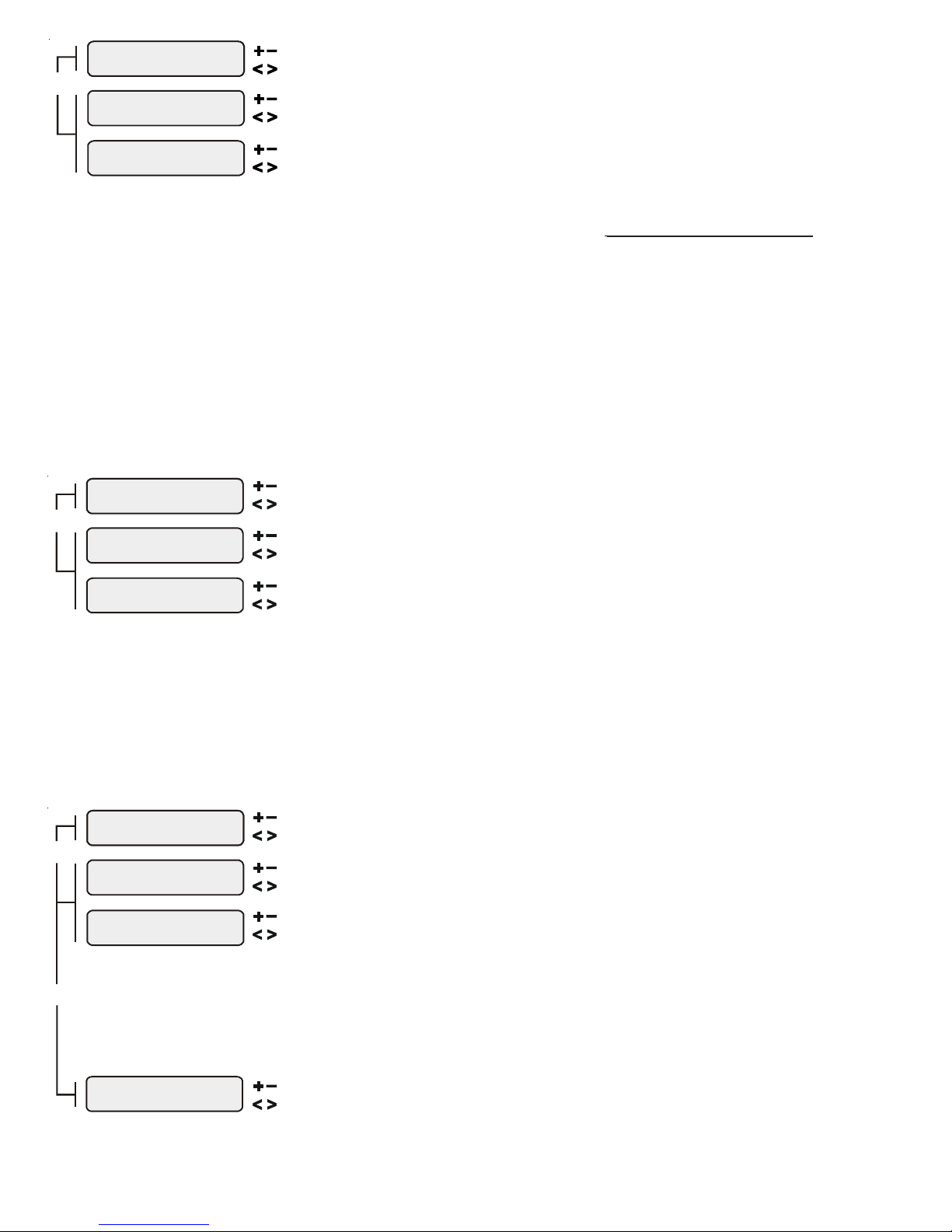
Spa Heater2
102°F
Spa Heater1
Off
Adjust the desired spa temperature (Off, 65°F, 66°F, ...103°F, 104°F, Off)
Adjust the desired spa temperature (Off, 65°F, 66°F, ...103°F, 104°F, Off)
Move to previous/next menu item
Move to previous/next menu item
not shown if Pool and Spa-Dual
with separate heaters is selected
with separate heaters is selected
Pool Heater2
85°F
Pool Heater1
Off
A
A
Move to previous/next menu item
Move to previous/next menu item
spa equipment. The chart on the previous page shows the Pro Logic’s six menus as well as each menu’s specific
settings.
The Default Menu is a series of informative displays (temperatures, salt levels, chlorinator settings, etc.) with
nothing to set. The Pro Logic will automatically switch to the default menu when no keys have been pressed for 2
minutes and will then scroll through each display.
The Settings Menu and the Timers Menu are the menus you will be using most often to adjust the operation of your
pool. The Configuration Menu is used when the system is installed and defines what equipment is connected to
each output and the operational logic that will control the equipment. This menu is normally “locked” and should
only be used by a pool professional. Details regarding the Configuration menu can be found on page 17.
The “Diagnostic Menu” is primarily intended for the service technician and contains information and details about
the system operation that are helpful in troubleshooting, if problems occur.
The “Maintenance Menu” will be displayed only if the optional AQL-CHEM is used and the Sensing System is
enabled in the Chemistry Config. Wizard. This menu is used to perform functions relating to the AQL-CHEM ORP
and pH sensing kit.
Settings Menu
The Settings Menu allows you to set all system operating parameters except the timeclock and countdown timers
which are part of the Timers Menu.
Important: All of the displays shown below use the default generic names for each function or
output. The Pro Logic allows more descriptive names to be assigned to each piece of equipment (refer
to the section regarding the Configuration Menu for more information).
The spa heater setting will only appear if the system has been setup for “spa only” or “pool and spa”
operation and the “Heater1” and/or “Heater2” control is enabled. The heater will turn on whenever
the pool/spa valves are in the “spa only” position and the filter pump is running and the spa water
temperature is less than the desired temperature setting. If you have both solar heat and a conventional
heater and the solar priority option is selected (Configuration Menu), then the conventional heater
will only operate when solar heat is NOT available.
For Pool and Spa dual equipment with separate heaters (“Pool and Spa -Dual” and “Htr1=Spa,
Htr2=Pool” selected), Spa Heater1 is tied to the Spa Filter (AUX1).
not shown if Pool and Spa-Dual
djust the desired pool temperature (Off, 65°F, 66°F, ...103°F, 104°F, Off)
The pool heater setting will only appear if the system has been setup for “pool only” or “pool and
spa” operation and the “Heater1” and/or “Heater2” control is enabled. The heater will turn on
whenever the pool/spa valves are in the “pool only” or “spa spillover” position and the filter pump is
running and the pool water temperature is less than the desired temperature setting. If you have both
solar heat and a conventional heater and the solar priority option is selected (Configuration Menu),
then the conventional heater will only operate when solar heat is NOT available.
For Pool and Spa dual equipment with separate heaters (“Pool and Spa -Dual” and “Htr1=Spa,
Htr2=Pool” selected), Pool Heater2 is tied to the Pool Filter (FILTER).
djust the desired pool temperature (Off, 65°F, 66°F, ...103°F, 104°F, Off)
8
Spa Heater2
Priority: 10 hours
Adjust the desired priority interval (Never, 1hr, 2hrs, 3hrs ...22hrs, 23hrs, Always)
Move to previous/next menu item
Pool
Priority: Never
Heater2
Adjust the desired priority interval (Never, 1hr, 2hrs, 3hrs ...22hrs, 23hrs, Always)
Move to previous/next menu item
Spa Solar
102°F
Adjust the desired spa temperature (Off, 65°F, 66°F, ...103°F, 104°F, Off)
Move to previous/next menu item
Pool Solar
88°F
Move to previous/next menu item
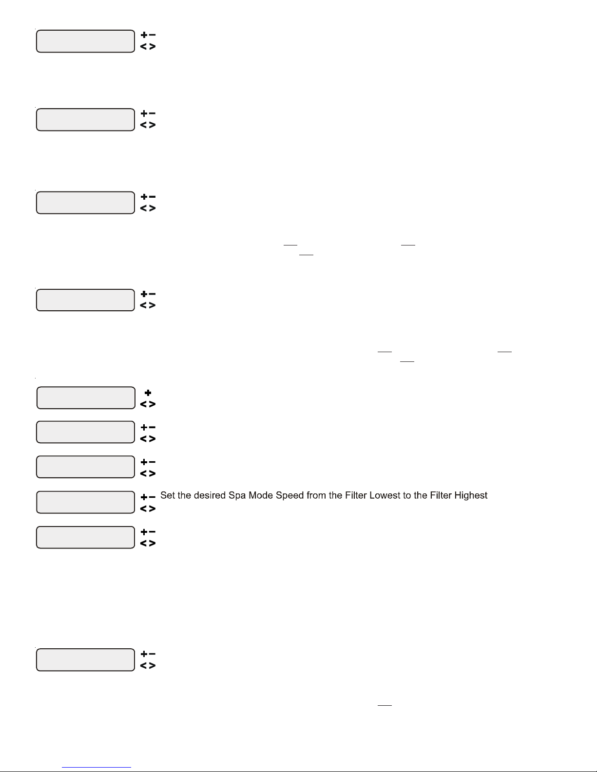
VSP Speed Settings
+ to enter
Spa Filter Speed 1
95%
Filter Speed 1
95%
Push to access Variable Speed Pump Speed Settings
Move to previous/next configuration menu
Move to next menu item
Spa Speed
50%
Move to next menu item
only if Filter is Variable Speed
only if Pool and Spa-Dual and Spa Filter is Variable Speed
Move to next menu item
Aux2 Speed
95%
Set the desired Aux2 Speed from 10% to 100%
Move to next menu item
only if Aux2 is controlled by a variable speed pump
Super Chlorinate
Off
POUNDS and (Kg) OF STABILIZER (CYANURIC ACID) NEEDED FOR 80 PPM
Gallons and (Liters) of Pool/Spa water
Current
Stabilizer
Level (ppm)
0 ppm
20 ppm
60 ppm
30 ppm
40 ppm
50 ppm
70 ppm
80 ppm
10 ppm
12,000
(45000)
8,000
(30000)
14,000
(52500)
10,000
(37500)
16,000
(60000)
18,000
(67500)
20,000
(75000)
22,000
(82500)
32,000
(120000)
24,000
(90000)
34,000
(127500)
26,000
(97500)
36,000
(135000)
28,000
(105000)
38,000
(142500)
30,000
(112500)
40,000
(150000)
8.0
(3.6)
5.3
(3.6)
8.0
(3.6)
8.0
(3.6)
9.4
(4.3)
6.7
(4.3)
9.4
(4.3)
10.7
(4.9)
12.0
(5.4)
12.0
(5.4)
13.4
(6.1)
14.7
(6.7)
21.3
(9.7)
16.0
(7.3)
22.7
(10.3)
18.7
(8.5)
25.3
(11.5)
20.0
(9.1)
26.7
(12.0)
7.0
)
(3.2
4.7
(3.2)
8.2
(3.7)
5.8
(3.7)
10.5
(4.8)
11. 7
(5.3)
12.9
(5.9)
18.7
(8.5)
14.0
(6.4)
19.8
(9.0)
15.2
(6.9)
21.0
(9.5)
16.4
(7.4)
22.2
(10.0)
17.2
(8.0)
23.3
(10.5)
6.0
(2.7)
4.0
(2.7)
6.0
(2.7)
6.0
(2.7)
8.5
(3.9)
7.0
(3.2)
9.0
(2.2)
10.0
(4.5)
10.0
(4.5)
14.2
(6.3)
11. 0
(5.0)
16.0
(7.2)
13.0
(5.9)
18.0
(8.1)
14.0
(6.4)
19.0
(8.6)
15.0
(6.8)
20.0
(9.0)
5.0
(2.3)
3.3
(2.3)
5.0
(2.3)
5.9
(2.7)
4.2
(2.7)
6.7
(3.0)
8.4
(3.8)
6.7
(3.0)
7.5
(3.4)
9.2
(4.2)
13.3
(6.0)
10.8
(4.9)
15.0
(6.7)
11.7
(5.2)
15.8
(7.1)
12.5
(5.6)
16.7
(7.5)
4.0
(1.8)
2.7
(1.8)
4.0
(1.8)
4.0
(1.8)
5.7
(2.6)
4.7
(2.1)
3.3
(2.1)
5.4
(2.4)
7.4
(3.3)
10.7
(4.8)
8.7
(3.9)
12.0
(5.4)
9.3
(4.2)
12.7
(5.7)
10.0
(4.5)
13.3
(6.0)
3.0
(1.4)
2.0
(1.4)
3.0
(1.4)
3.5
(1.6)
2.5
(1.6)
4.5
(2.0)
5.5
(2.5)
8.0
(3.6)
6.5
(2.9)
9.0
(4.1)
7.0
(3.2)
9.5
(4.3)
7.5
(3.4)
10.0
(4.5)
2.0
(.91)
1.3
(.91)
2.0
(.91)
2.8
(1.3)
2.3
(1.1)
1.7
(1.1)
2.7
(1.2)
3.3
(1.5)
3.7
(1.7)
5.3
(2.4)
4.3
(2.0)
4.7
(2.1)
6.3
(2.8)
5.0
(2.3)
6.7
(3.0)
1.0
(.45)
0.7
(.45)
1.2
(.54)
0.8
(.54)
1.4
(.64)
1.5
(.68)
1.7
(.77)
1.8
(.82)
2.7
(1.2)
2.2
(1.0)
3.0
(1.3)
2.3
(1.1)
3.2
(1.4)
2.5
(1.2)
3.3
(1.5)
0.00.0 0.00.0 0.0 0.0 0.0 0.0
0.00.0 0.00.0 0.00.0 0.00.0 0.0
The spa heater priority setting will only appear if the system has been setup for “spa only” or “pool
and spa”and if priority has been enabled for Spa Heater2. Choose “Never”, “Always” or a selectable
time interval. If an interval is selected, only Spa Heater2 will run when there is a call for heat. After the
interval expires, both heaters will be allowed to operate until the desired temperature has been reached.
The pool heater priority setting will only appear if the system has been setup for “pool only” or “pool
and spa”and if priority has been enabled for Pool Heater2. Choose “Never”, “Always” or a selectable
time interval. If an interval is selected, only Pool Heater2 will run when there is a call for heat. After the
interval expires, both heaters will be allowed to operate until the desired temperature has been reached.
The spa solar setting will only appear if the system has been setup for “spa only” or “pool and spa”
operation and the solar control is enabled. The solar system will turn on whenever the pool/spa
valves are in the “spa only” position and the filter pump is running and the spa water temperature is
less than the desired temperature setting and solar heat is available.
Adjust the desired pool temperature (Off, 65°F, 66°F, ...103°F, 104°F, Off)
The pool solar heater setting will only appear if the system has been setup for “pool only” or “pool
and spa” operation and the solar control is enabled. The solar system will turn on whenever the pool/
spa valves are in the “pool only” or “spa spillover” position and the filter pump is running and the
pool water temperature is less than the desired temperature setting and solar heat is available.
only if an output is configured for a variable speed pump
only if Pool and Spa-Std and Filter is Variable Speed
Set the desired Filter Speed 1 from the Filter Lowest to the Filter Highest
Set the desired Spa Filter Speed 1 from the Spa Filter Lowest to Spa Filter Highest
The Filter, Dual Equipment Spa Filter, and up to 6 Lights and Aux outputs can be configured to control
variable speed pumps. These settings allow you to select the desired speed of the variable speed
pump for each output used. The speed can be displayed in % or RPM, whichever is selected in the
Configuration Menu. For the Filter and Dual Equipment Spa Filter, when the output is on, the actual
speed of the pump(s) will be dependent on the minimum and maximum speeds set for that output in the
Configuration Menu.
Turn super chlorinate on or off
Move to previous/next menu item
This display only appears if the chlorinator function is enabled. If an AQL-CHEM is being used, super
chlorinate will not be available if chemical sensing is enabled and ORP is in Auto Sensing (see AQLCHEM manual).
9
When you have an unusually high bather load, a large amount of rain, a cloudy water condition, or any
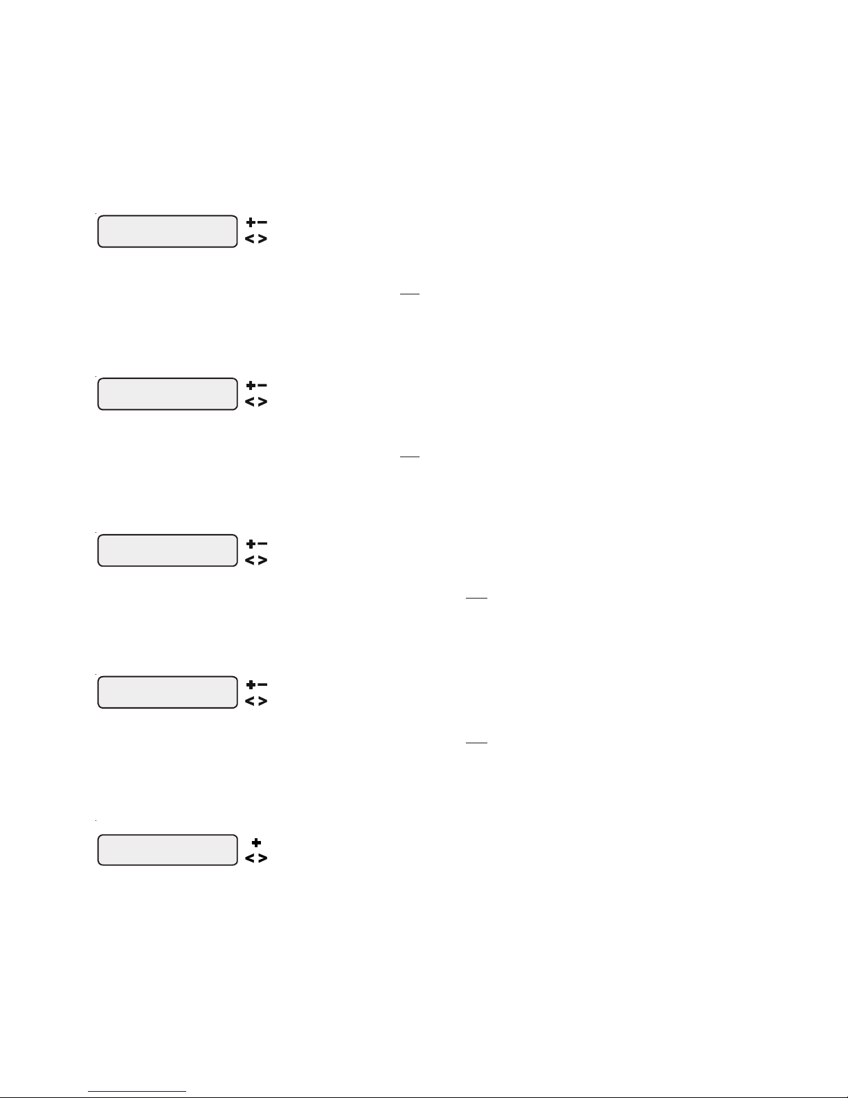
Spa Chlorinator
3%
Move to previous/next menu item
Pool Chlorinator
60%
Move to previous/next menu item
Pool High Speed
100%
Adjust the desired high speed for variable speed operation
Move to previous/next menu item
Pool Low Speed
50%
Adjust the desired low speed for variable speed operation
Move to previous/next menu item
Aux1 Settings
+ to view/change
other condition that requires a large amount of chlorine to be introduced to the pool, activate the Pro
Logic Super Chlorinate function. The Pro Logic will turn on the filter pump, set the pool/spa valves to
the correct position, and set the chlorine generator to maximum output. The superchlorinate function
will continue for the programmed number of hours (see Timers/Super Chlorinate Hours) overriding the
normal filter pump timeclock settings. At the end of the super chlorinate period, the pool will return to
normal operation.
If you manually turn off the filter pump (using the “FILTER” button on any display/keypad), the super
chlorinate function terminates. When you turn the filter pump back on, super chlorinate will resume for
the balance of the programmed number of hours.
Adjust the desired chlorinator output for spa (0,1,2,3...9,10,15,20...95,100%)
This setting will appear only if the chlorinator function is enabled and system has been setup for “spa
only” or “pool and spa-std”. If an AQL-CHEM is being used, super chlorinate will not be available if
chemical sensing is enabled and ORP is in Auto Sensing (see AQL-CHEM manual). It will determine
the chlorinator output when the system is operating in spa-only mode. The actual amount of chlorine
introduced into the spa is determined by: this setting, the amount of time the pool operates in spa-only
mode, the water temperature, and the amount of salt in the water. If the filter pump is running due to the
freeze protection feature, then the chlorinator will not operate during this time.
Adjust the desired chlorinator output for pool (0,1,2,3...9,10,15,20...95,100%)
This setting will appear only if the chlorinator function is enabled and system has been setup for “pool
only” or “pool and spa”. If an AQL-CHEM is being used, super chlorinate will not be available if
chemical sensing is enabled and ORP is in Auto Sensing (see AQL-CHEM manual). It will determine
the chlorinator output when the system is operating in pool-only or spa spillover modes. The actual
amount of chlorine introduced into the pool is determined by: this setting, the amount of time the filter
pump is running, the water temperature, and the amount of salt in the water. If the filter pump is running
due to the freeze protection feature, then the chlorinator will not operate during this time.
This setting will appear if “spa only” is not selected and variable speed filter pump is enabled. This
setting determines the speed of the pump during high speed pool or spillover operation. This value
can be set from 20% to “Highest Speed” in 5% increments. “Highest Speed” is default.
For PS models using dual equipment, this is the pool filter high speed.
This setting will appear if “spa only” is not selected and variable speed filter pump is enabled. This
setting determines the speed of the pump during low speed pool or spillover operation. This value can
be set from “Lowest Speed” to 50% in 5% increments. 50% is default.
For PS models using dual equipment, this is the pool filter low speed.
if Aux1 is configured as "ColorLogic"
This menu will appear if an aux has been configured as “ColorLogic”. Use this menu to select custom
colors and lightshows for your networked ColorLogic lights. Refer to the AQL-COLOR-MODHV
manual for specific information on these settings.
Push to access ColorLogic settings
Move to previous/next menu item
10

Set Day and Time
Wednesday 10:37P
Adjust the current day of the week
Move to hours setting
Set Day and Time
10:37P
Set Day and Time
Wednesday 37
Set Day and Time
Wednesday 10: P
Adjust the current hour (including AM/PM if applicable)
Adjust the current minute
Move to minutes setting
Move to previous/next menu item
Display Light
On for 60 sec
Move to previous/next menu item
Beeper
Enabled
Toggle between
Move to previous/next menu item
Teach Wireless
+ to start
Teach
Successful
Wireless
Teach
NOT Successful
Wireless
Teach Wireless
Base NOT Found
Press and hold
wireless button
Move to previous/next menu item
Move to previous/next menu item
Move to previous/next menu item
Move to previous/next menu item
Move to previous/next menu item
Gallons
Liters
Rectangular
Round
Oval
Diameter x Diameter x
Average Depth x 5.9
Length x Width x
Average Depth x 6.7
Length x Width x
Average Depth x 7.5
Average Depth x 785
Length x Width x
Average Depth x 893
Length x Width x
Average Depth x 1000
Use this function to set the current day of the week and time. These values are used for all the
automatic timeclock functions of the Pro Logic and are also displayed as part of the default menu.
The Pro Logic is designed to keep the clock running during power outages lasting less than 7 days. If
power has been off for longer than 7 days, then the time may have to be reset.
Toggle between Always On and On for 60 sec.
This function controls the backlight on the display. If the “On for 60 seconds” option is selected, then
the backlight will automatically turn off 60 seconds after the last key is pressed and will stay off until
next time a key is pressed.
Note that the Display Light selection only applies to the display keypad that you are currently using.
Other display/keypads will not be affected. You need to individually set this option for each display/
keypad in the system.
Enabled (default) and Disabled Beeper
When “Enabled”, the keypad will beep every time a key is pressed. If this audible indication is not
desired, select “Disabled”.
This function only applies to the display/keypad that you are currently using. You need to set this
option for each display/keypad in your system.
NOTE: This function is not supported on all display/keypads. If the “Enabled” selection is not
blinking, then the current software revision of that particular keypad/display does not support the
option and it will default to Beeper Enabled.
Push to start process
Press any button on wireless remote
This menu will only appear if a wireless base station is connected to the Pro Logic. Perform this
procedure each time a wireless remote control is added to the Pro Logic system. During this procedure
the wireless remote “learns” and remembers the ID code for the wireless base station connected to
this particular Pro Logic unit and will reject messages with any other ID codes. If “Base NOT found”
is displayed, then the Pro Logic can not communicate with the transmitter/receiver base station
attached to the main unit. If “NOT Successful” is displayed, then the base station did not receive a
signal from the remote control. This may be due to the distance between the Base Receiver and the
remote device being too great or may be due to interference caused by other RF equipment operating
in the neighborhood. Try using the “Change Channel” command and then repeat the “Teach Wireless” command.
11

Wireless
Channel: 1
Reteach all
wireless units
Confirm Change:
+ to proceed
Push to confirm the channel change
Change the desired wireless channel (1 - 5)
Move to previous (Teach Wireless) menu
Move to previous/next menu item
!
Set Day and Time
Wednesday 10:37P
Move between start and stop times & to previous/next menu item
Filter T1-all
8:30A to 4:00P
Filter T1-wkend
8:30A to 4:00P
Filter T1-wkday
8:30A to 4:00P
Adjust time setting
Adjust time setting
or
If channel is changed, move to confirmation menu
If channel is not changed, move to previous/next menu item
This setting changes the channel to be used by the wireless base station and remote(s). If the channel
is changed and confirmed, all wireless remote will have to be re-taught. This menu will only appear if
a wireless base station is connected to the Pro Logic.
Timers Menu
The Timers Menu allows you to set all timeclock and countdown timers which control the automatic operation of
your pool/spa system.
Most timeclocks have a single on/off program per day. All of the timeclocks are setup (Configuration Menu) either
as “all days” or “weekends/weekdays”. If “weekends/weekdays” are selected, you will need to program on times
for both weekdays and weekends and off times for both weekdays and weekends, even if you want them to be the
same. All times are adjusted in 15 minute increments (9:00A, 9:15A, 9:30A, etc.). If you program the on time
equal to the off time (“10:00A to 10:00A”) the output will NEVER turn on. If you want to disable a timeclock, you
can set the on time equal to the off time and you will notice the times disappear and the display simply shows “Off”.
If, at a later time, you wish to re-activate the timeclock, simply press either the “+” or “-“ buttons to go back to a
normal timeclock programming display.
The Countdown timer is programmed in increments of 5 minutes from “Manual On/Off” (0 minutes) to a maximum
of “21:00” (21 hours). When “Manual On/Off” is displayed, the countdown timer is disabled and the output will be
manually controlled. When a countdown timer is equal or greater than “0:05”, pressing the appropriate output
button will turn the output on and start the timer. Pressing the button again will turn the output off or, when the
programmed time has elapsed, the output will automatically turn off.
Important: All of the displays shown below use the default generic names for each function or
output. The Pro Logic allows more descriptive names to be assigned to each piece of equipment (refer
to the section regarding the Configuration Menu for more information).
Adjust time setting
Move between start and stop times & to previous/next menu item
Move between start and stop times & to previous/next menu item
For one speed pumps, this is the first filter timeclock and will determine the normal hours of filtration
for the pool. For pool/spa combination systems with spillover enabled and filter operation set to
“spillover”, the valves will automatically switch to spillover mode at the start of the filtration period.
For pool/spa combination systems with spillover enabled and filter operation set to “pool only”, the
valves will switch to the pool-only position.
For two speed pumps, this setting will be the period of time when the pump runs at high speed (the
word “Filter T1” in the display will be replaced with “Filter H1”). There is a separate timeclock for the
low speed operation which will be programmed next . If the high speed and low speed periods overlap,
then the pump will operate in low speed during the overlap period.
For a variable speed pump, this setting will be the period of time when the pump will run at the speed
selected for speed1 in the settings menu. If there is an overlap in any of the timeclocks, then the lower
number timeclock/speed has priority.
Depending on the type of filter pump used, there are several reasons why the pump may be running
at times other than the timeclock period set above. These include super-chlorination, spa operation,
manual operation, heater cooldown, freeze protection, heater-extend and solar-extend. For variable
speed pumps, when there is more than one reason for the pump to run, the speed priority in order from
highest to lowest is priming (first 3 minutes after filter has been turned on), freeze protection, group,
heater minimum, aux/valve override, spa mode, speed1, speed2, speed3, speed4. Note that the reason
for the current speed is shown in the Default Menu.
12
Set Day and Time
Wednesday 10:37P
Adjust time setting
Move between start and stop times & to previous/next menu item
Filter T2-all
8:30A to 4:00P
Filter T2-wkend
8:30A to 4:00P
Filter T2-wkday
8:30A to 4:00P
Adjust time setting
Adjust time setting
or
Set Day and Time
Wednesday 10:37P
Move between start and stop times & to previous/next menu item
Spa-all
6:00P to 9:00P
Spa-wkend
6:00P to 9:00P
Spa-wkday
6:00P to 9:00P
Adjust time setting
Adjust time setting
or
Set Day and Time
Wednesday 10:37P
Move between start and stop times & to previous/next menu item
Lights-all
8:00P to 11:00P
Lights-wkend
8:00P to 11:00P
Lights-wkday
8:00P to 11:00P
Adjust time setting
Adjust time setting
or
or
Lights-CountDn
0:20
Adjust time setting (Manual On/Off, 0:05, 0:10, 0:015...)
Move to previous/next menu item
Move between start and stop times & to previous/next menu item
Move between start and stop times & to previous/next menu item
For one speed pumps, this is the second filter timeclock.
For two speed, this timeclock will set the normal time period for filter pump low speed operation (the
word “Filter T2” in the display will be replaced with “Filter L1”). If the filter pump is off for more than
30 seconds, the pump will first turn on at high speed for 3 minutes to prime and establish water flow.
Afterwards, it will drop down to low speed for the remainder of the programmed low speed time period.
While this time clock will override the high speed timeclock (see above), there are several reasons why
the pump will automatically switch to high speed operation during this programmed time period.
These include manual operation, spa operation, or heating operation.
For a variable speed pump, this setting will be the period of time when the pump will run at the speed
selected for speed2 in the settings menu. If there is an overlap in any of the timeclocks, then the lower
number timeclock/speed has priority.
NOTE: The third and forth filter timeclocks function similarly to the first and second (respectively). Program these timeclocks
in the same manner.
Adjust time setting
Move between start and stop times & to previous/next menu item
Move between start and stop times & to previous/next menu item
This menu is only available if the system has been setup for “pool and spa-std”. During the programmed
spa time, the Pro Logic will move the pool/spa valves into the “spa-only” position and turn on the
filter pump. The heater will automatically heat the spa up to the programmed spa temperature. This
programmed spa operation will take precedence over all other automatic functions, only manual
operation of the filter button or pool/spa valve button will override this function.
If your pool has a separate jet pump or blower controlled by Aux1 and/or Aux2 , you will have to
program those separately.
Adjust time setting
Move between start and stop times & to previous/next menu item
Move between start and stop times & to previous/next menu item
This menu will appear only if the Lights are configured for timeclock. The lights will turn on and off at
the designated times. The only override on this function is manual on/off control by the “Lights”
button.
This menu will appear only if the Lights are configured for countdown timer. This setting is the time
after you manually turn on the lights until the Pro Logic automatically turns off the lights. You can
also manually turn off the lights at an earlier time by pressing the LIGHTS button.
13
 Loading...