

Hayward OmniHub Installation Manual

Hayward Pool Products
620 Division Street, Elizabeth NJ 07207
Phone (908)-355-7995
www.hayward.com
OmniHub
Pool Automation Control
Installation Manual
Contents
Before you Begin.....................3
Mounting...............................8
Plumbing..............................10
Wiring...................................11
Startup................................23
Conguration........................24
092711 RevA
HLOMNIHUB
USE ONLY HAYWARD GENUINE REPLACEMENT PARTS

FCC Statement
This device complies with part 15 of the FCC rules. Operation is subject to the following two conditions:
(1) This device may not cause harmful interference, and (2) this device must accept any interference
received, including interference that may cause undesired operation.
Changes or modifications not expressly approved by Hayward could void the user’s authority to
operate this equipment.
NOTE: This equipment has been tested and found to comply with the limits for a Class B digital device,
pursuant to Part 15 of the FCC Rules. These limits are designed to provide reasonable protection
against harmful interference in a residential installation. This equipment generates, uses and can
radiate radio frequency energy and, if not installed and used in accordance with the instructions, may
cause harmful interference to radio communications. However, there is no guarantee that interference
will not occur in a particular installation. If this equipment does cause harmful interference to radio
or television reception, which can be determined by turning the equipment off and on, the user is
encouraged to try to correct the interference by one or more of the following measures:
-- Reorient or relocate the receiving antenna.
-- Increase the separation between the equipment and receiver.
-- Connect the equipment into an outlet on a circuit different from that to which the receiver is
connected.
-- Consult the dealer or an experienced radio / TV technician for help.
Industry Canada Statement
This Class B digital apparatus complies with Canadian ICES-003.
Cet appareil numérique de la classe B est conforme à la norme NMB-003 du Canada.
The term “IC” before the certification / registration number only signifies that the Industry Canada
technical specifications were met.
1
USE ONLY HAYWARD GENUINE REPLACEMENT PARTS

Table of Contents
Before you Begin.......................................................................................................3
Overview..................................................................................................................4
Mounting
Wiring Hub.......................................................................................................8
Control Pad......................................................................................................8
Smart Relay......................................................................................................9
Temperature Sensors........................................................................................10
Plumbing................................................................................................................10
Electrical Wiring
High Voltage...................................................................................................12
Low Voltage....................................................................................................18
System Startup.........................................................................................................23
Configuration
Pre-Programmed Configuration........................................................................26
Typical Configuration.......................................................................................27
Advanced Configuration..................................................................................29
Quick Edit..............................................................................................................47
Control Pad Mounting Template.................................................................................57
USE ONLY HAYWARD GENUINE REPLACEMENT PARTS
2
USE ONLY HAYWARD GENUINE REPLACEMENT PARTS
2

Before you Begin
What’s Included
Check that the following components have been included in your package:
• Wiring Hub
• Control Pad
• Smart Relay
• 2 Temperature Sensors
• 15 ft, 2 conductor (red and black) cable for low voltage connection to Wiring Hub from a variable speed pump (VSP) or Heater
• 2 Wiring Whips - 6 ft flexible conduit containing three 12AWG conductors (red, black and
green) for filter pump and Smart Relay installation. A length of white 12 AWG conductor is
included to replace red for 115 VAC pump and Smart Relay applications
• Input Power Wiring harness and miscellaneous installation hardware
Note that your OmniHub may have been packaged with additional equipment and may contain specific installation information on a separate Quick Start guide.
What’s NOT Included
Some of the additional items that you may need to complete an installation include:
Wire
• Wire/conduit for incoming power
• Wire for remote variable speed pump control and other low voltage devices
• Ethernet cable (if not using wifi)
Miscellaneous
• Valve actuator to automate pool functions
• Flow switch for optional pump protection/flow monitoring. A flow switch is required if using
Sense and Dispense accessories
• Mounting hardware for mounting Wiring Hub, Control Pad and Smart Relay
• Cable/cord connectors to provide knockout strain relief
• Wire nut connectors
• USB thumbstick (to update firmware)
Tools Needed
Phillips and flat screwdrivers Wire cutters and strippers Knife to cut conduit
Drill and drill bits (including 3/8") Pliers Level
Accessory Products - Order Separately
HLH485RELAY Smart Relay used for controlling additional pool equipment
GLX-FLO Flow Switch used to detect water flow
GVA-24 Valve Actuator
2PC Temperature Sensor for 3rd input
3
USE ONLY HAYWARD GENUINE REPLACEMENT PARTSUSE ONLY HAYWARD GENUINE REPLACEMENT PARTS

HL-CHEM ORP & pH Sensing Kit for monitoring and controlling pool chemistry (requires
GLX-FLO flow switch)
HL-CHEM4-ACID Liquid acid feeder (requires GLX-FLO flow switch)
HL-CHEM4-CHLOR Liquid chlorine feeder (requires GLX-FLO flow switch)
CL200 Chlorine tablet feeder
HLAQR940 Aqua Rite chlorine generator
AQR940/AQR925 Aqua Rite chlorine generator (requires HLAQRPCB)
Overview
The Hayward OmniHub is a web enabled pool automation control with a convenient touchscreen
interface. Automatically and remotely control the pumps, a heaters, valve actuators, pool and yard
lighting, pool chemistry equipment and more. The OmniHub offers the next generation of technology
to manage pool/spa equipment, allowing communication to web connected computers and mobile
devices. You can now conveniently monitor your pool/spa and change settings anytime, and from
anywhere.
Please read this manual thoroughly before attempting to install, configure or operate this unit. A
Quick Start guide may have also been included to offer concise information specific to your equipment.
Features
The standard Hayward OmniHub offers the following functionality:
• controls up to 3 variable speed pumps* (VSPs) for pool/spa filtration and water features
• controls up to 3 Smart Relays to turn on/off single speed pumps, pool lights, yard lights, water
features, chemical dispensers and more
• controls up to two valve actuators allowing you to manage two bodies of water (both pool and
spa) or can be used for water features, cleaners, solar heating, etc.
• controls one conventional heater (electric heat pump or gas) and optional solar heater (for single
body of water applications only)
• inputs for up to 3 temperature sensors or external input devices
• built-in wireless to connect to the home’s router/access point (Ethernet port provided for optional
wired connection)
• optional flow switch used to protect pool equipment by detecting water flow
• controls an optional Sense and Dispense module (HL-CHEM) which monitors the pool's pH and
ORP and can dispense acid for pH control and chlorine for ORP control (requires additional equipment)
• controls an optional Hayward Aqua Rite salt chlorinator. If controlled by the OmniHub, the Aqua
Rite must have a HLAQRPCB communication board installed
Optional accessories (page 3) can expand the functionality of the OmniHub. Determine your needs
and select the necessary accessories before you begin the installation.
* If a non-Hayward brand VSP or an older non-supported Hayward VSP will be used, the pump can only operate at one speed.
The pump must be locally programmed to run 24 hrs/day at a fixed speed and the OmniHub will turn it on and off based
on the desired programmed time. Follow instructions to install and function like a single speed pump, using a Smart Relay.
USE ONLY HAYWARD GENUINE REPLACEMENT PARTS
4
USE ONLY HAYWARD GENUINE REPLACEMENT PARTS

Equipment
Wiring Hub
All incoming/outgoing wiring will be connected to the Wiring Hub. The OmniHub can be powered
by either 230 VAC or 115 VAC. Input power should be constant, not from a timer. If a timer must be
used, set the timer to power the Wiring Hub continuously. For convenience, 6 ft Wiring Whips with
red, white, black and green colored 12AWG wires are included with the OmniHub.
The remaining connections to the Wiring Hub, including the Control Pad, are all low voltage. Depending on your installation, these connections could be to a variable speed pump, Smart Relays,
temperature sensors, actuator and a flow switch.
Control Pad
The Control Pad is weather resistant and comes with a 15 ft cord. Its resistive touch screen with flip
down cover is designed to function year round directly in the elements. Because it plugs into the Wiring Hub, it should be mounted close by, but in a location that is convenient for the user to periodically
view and change pool/spa settings. Lastly, the Control Pad contains the Wifi radio and its location
should be considered if planning to use a wireless connection to the home router or access point. A
wireless mobile device (phone, tablet, etc.) could be used to test the signal strength at the intended
mounting location. The Control Pad features a USB connector for firmware updates and an Ethernet
connector for an optional direct wire connection to your router (if wifi won't be used).
Smart Relay
Smart Relays have a 15 ft communication cable that connects to the Wiring Hub and are used to
control high voltage pool equipment like lights, water features, pumps and more. 115 VAC or 230
VAC power to the intended load must be supplied separately and run through the Smart Relay. Smart
Relays are rated for up to 20 amps at 230 volts.
Temperature Sensors
Depending on your installation, up to 3 temperature sensors may be used. The OmniHub requires
a water temperature sensor for heater operation. If freeze protection is desired, an air temperature
sensor is also required. For solar heating systems, a solar sensor is necessary. Even if your installation doesn't require the use of temperature sensors, installing water and air sensors provides a
convenience to the user, especially during remote use.
Flow Switch (not included)
An optional flow switch can be used to detect leaks or clogs in the pool/spa plumbing. A flow switch
is required if using chemistry Sense and Dispense accessories.
Overview
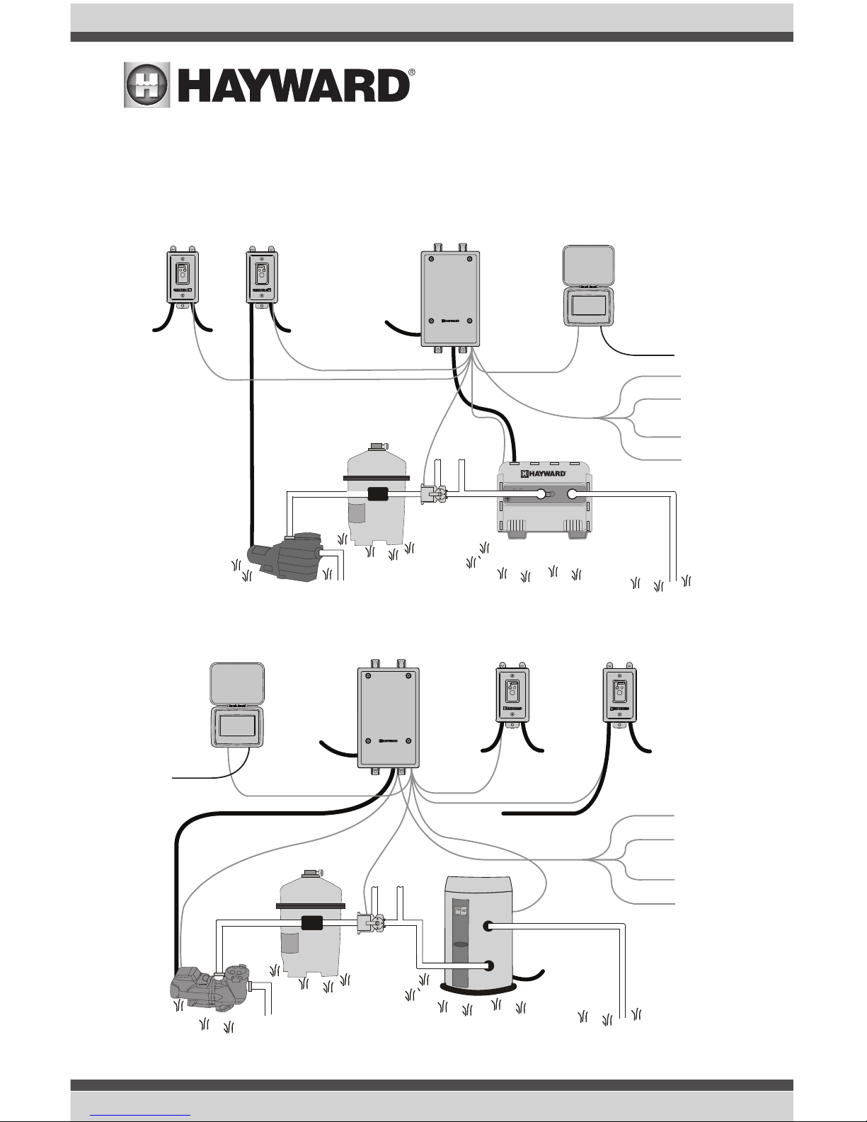
Before attempting to install the OmniHub, familiarize yourself with the installation steps on the following pages. Also refer to the sample overview diagrams on page 6. Diagram 1 shows wiring
to a single speed pump and a conventional gas heater. Single speed (and two speed) pumps are
controlled by Smart Relays. In this example the high voltage for the conventional gas heater is wired
in parallel with the Wiring Hub. A Wiring Whip is used for this connection. A separate remote control
connection is made from the Wiring Hub to the heater.
5
USE ONLY HAYWARD GENUINE REPLACEMENT PARTS
Pump Input Power or
Existing Timeclock
Wiring Hub
(Optional)
Smart Relay 2
Single Speed
Pump
Filter
Valve
Actuator
TO
POOL
FROM
POOL
Comm. to Smart
Relay 1 (15’)
Heater
Remote
Control
Comm. to
Valve
Actuator
To Solar
REMOTE
RELAY
OFFLINE:
ON/OFF
Smart Relay 1
Comm. to Smart
Relay 2 (15’)
Control Pad
To Feature,
Accessory,
Lights, etc.
Wireless
Connection
OR
Ethernet to
Router
Comm. to
Controller (15’)
Sensor 1
(Water Temp.)
Sensor 2
(Air Temp.)
Sensor 3 (Solar OR
External Input)
(Optional)
Flow Switch
REMOTE
RELAY
OFFLINE:
ON/OFF
Wiring Whip from Hub
(gas heaters only)
Heater
Power
from
Smart
Relay
refer to additional information in this
manual if using a two speed or
variable speed filter pump
Input
Power
Input Power
for Hub and
Heater
(Gas models)
Input Power or
Existing Timeclock
Wiring Hub
(Optional)
Smart Relay 2
To Feature,
Accessory,
Lights, etc.
Variable
Speed Pump
Filter
Valve
Actuator
Heater
TO
POOL
FROM
POOL
Power
to VSP
if same
voltage
as Hub
Input Power to
Smart Relay 1
Comm. to Smart
Relay 1 (15’)
Heater
Remote
Control
Comm. to
Valve Actuator
Comm.
to VSP
To Solar
REMOTE
RELAY
OFFLINE:
ON/OFF
Smart Relay 1
Input
Power
Comm. to Smart
Relay 2 (15’)
Control Pad
To Feature,
Accessory,
Lights, etc.
Wireless
Connection
OR
Ethernet to
Router
Comm. to
Controller (15’)
Sensor 1
(Water Temp.)
Sensor 2
(Air Temp.)
Sensor 3 (Solar OR
External Input)
(Optional)
Flow Switch
REMOTE
RELAY
OFFLINE:
ON/OFF
Wiring Whip
Heat pumps require
input power directly
from electrical panel
Diagram 2 shows wiring to a supported VSP and electric heat pump heater. Variable speed pumps
must have constant input power and require a communication connection to the Wiring Hub. In this
example, the high voltage VSP is wired in parallel with the Wiring Hub. Heat pumps, which require a
separate circuit from the electrical panel, only have a remote control connection to the Wiring Hub.
Diagram 1
Diagram 2
USE ONLY HAYWARD GENUINE REPLACEMENT PARTS
6

These Overview diagrams are offered as a guide and it's likely that your installation will require
you to use some combination of two configurations. Refer to the following pages for specific wiring
information and note the required voltage for each piece of equipment. Keep in mind that the Wiring Hub can be powered by either 115 VAC or 230 VAC when wiring equipment in parallel. Lastly,
be aware of each circuit breaker's rating and don't exceed their rated load.
Installation
Installation Steps
DANGER of Death, Injury or Property Damage if procedure not followed. Power wiring must
be shut off before attempting to install the OmniHub.
The OmniHub is designed to be mounted outdoors at the pool pad. Both the Wiring Hub and the
Control Pad are water resistant and can be left out for the winter. Details on each installation step
are shown below:
1. Mounting the equipment (page 8)
Wiring Hub
Control Pad
Smart Relay
Temperature sensors
Valve actuators (if applicable)
2. Plumbing (page 10)
General Pool Equipment
Flow Switch
3. Electrical Wiring (page 11)
Wiring Hub power
Grounding
Wiring (Pool Pump Communication, Heater, Smart Relays, Temperature Sensors, Flow Switch,
etc.)
5. System Startup and Firmware Upgrade (page 23)
Your OmniHub may have been packaged with additional equipment and may contain specific installation information on a separate Quick Start guide. If so, refer to both this document and your Quick
Start guide for installation instructions.
7
USE ONLY HAYWARD GENUINE REPLACEMENT PARTS

Mounting the
Equipment
Wiring Hub
The Wiring Hub is contained in a raintight enclosure
that is suitable for outdoor mounting. It must be
mounted a minimum of 6 ft (2 meters) horizontal
distance from the pool/spa (or more, if local codes
require). The Wiring Hub is designed to mount vertically with the knockouts facing downward. Do not
mount the Wiring Hub inside a panel or tightly enclosed area.
When selecting a location, note that the standard
cables supplied with the optional flow switch, temperature sensors, and actuators are all 15 ft (5m)
long. Additional low voltage connections will have
to be made to the heater and VSP, if used. 230 VAC or 115 VAC input power must also be run to
the Wiring Hub. Try to mount the Wiring Hub in a location where incoming/outgoing wiring will be
easily accessible.
Mount the Wiring Hub on a wall or flat surface. Select mounting hardware that is appropriate for the
mounting surface and material. The Wiring Hub has two keyhole type mounting tabs on the top and
bottom of the enclosure requiring a total of 4 fasteners.
Control Pad
The Control Pad comes with a 15 ft cord and plugs into the Wiring Hub. It should be mounted in a
location that is convenient for the user to view and change pool/spa settings. When considering the
mounting location, make sure there is enough clearance above the enclosure so that the flip door
will be able to be opened fully. Also be sure to allow enough clearance below the Control Pad to
access the USB and Ethernet connectors. For best viewing results, position the Control Pad where it
won't be subjected to direct sunlight.
The Control Pad has two keyhole cutouts on the back of its enclosure. To mount, screw the two
provided fasteners into the mounting surface at the desired location using the template found on
page 57. Tighten until the bottom of the screw heads are 1/8" off the mounting surface. Position the
Control Pad cutouts over the screw and slide the unit downward. You may have to tighten or loosen
the screws slightly to fully engage the screw heads to get a snug fit.
USE ONLY HAYWARD GENUINE REPLACEMENT PARTS
8
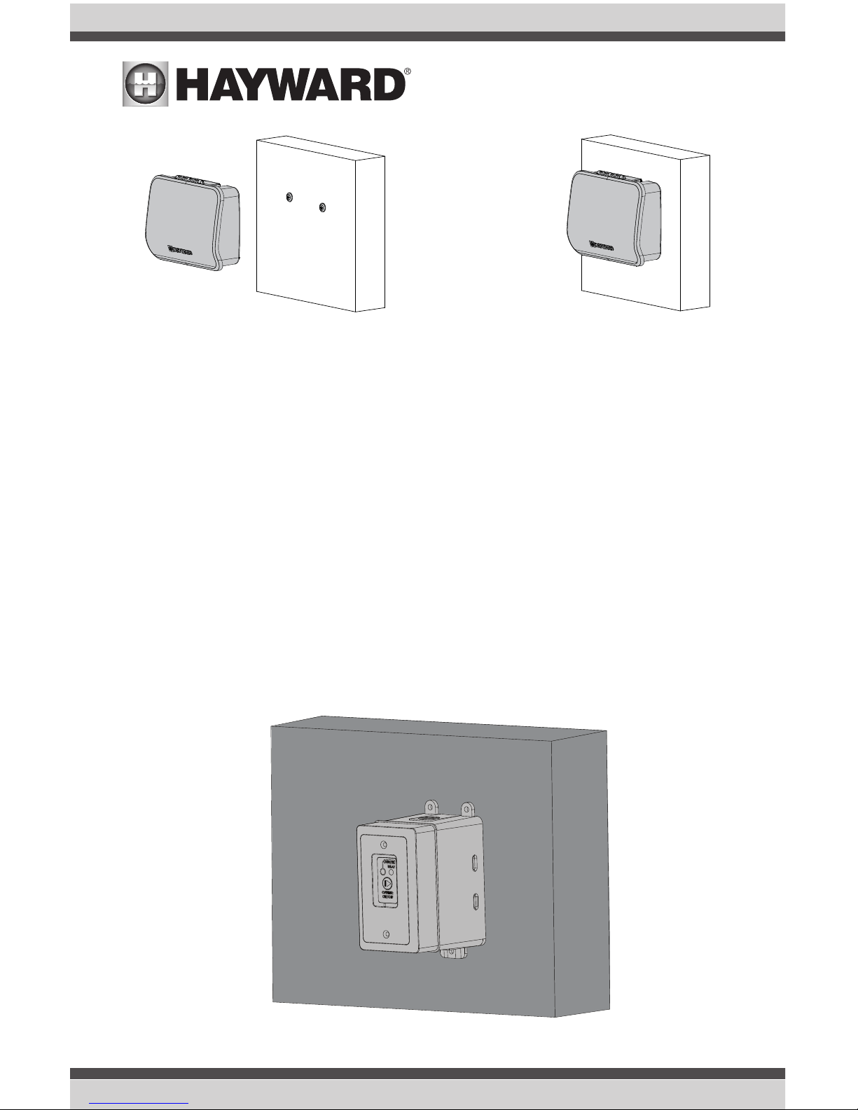
Smart Relay
The Smart Relay is packaged with a single gang electrical box but can also be used with any existing
comparable standard electrical box with a minimum volume of 16.2 in3. If using 115 VAC, make
sure that there is a Neutral line inside the box before installation. If not, you must run a separate
Neutral wire to power the Smart Relay. This is not a concern if using 230 VAC. Note that conduit and
connections to the included plastic box must be non-metallic.
Find a location within 15 ft of the Wiring Hub with convenient access to the pool equipment that
you intend to control with the Smart Relay. Three threaded 1/2" NPT knockouts are provided for
high voltage power coming into the relay and for power out to the pool equipment. A Wiring Whip
is included to aid installation.
The Smart Relay has a manual On/Off button that can be used if communication is lost with the
Wiring Hub. Although this button is not functional during normal operation, mount the Smart Relay in
an accessible location to use this feature in case of communication loss. Refer to page 17 for Smart
Relay LED information.
Mount the Smart Relay to a wall or other flat surface using the mounting holes which are designed
to accommodate #8 screws.
9
USE ONLY HAYWARD GENUINE REPLACEMENT PARTS

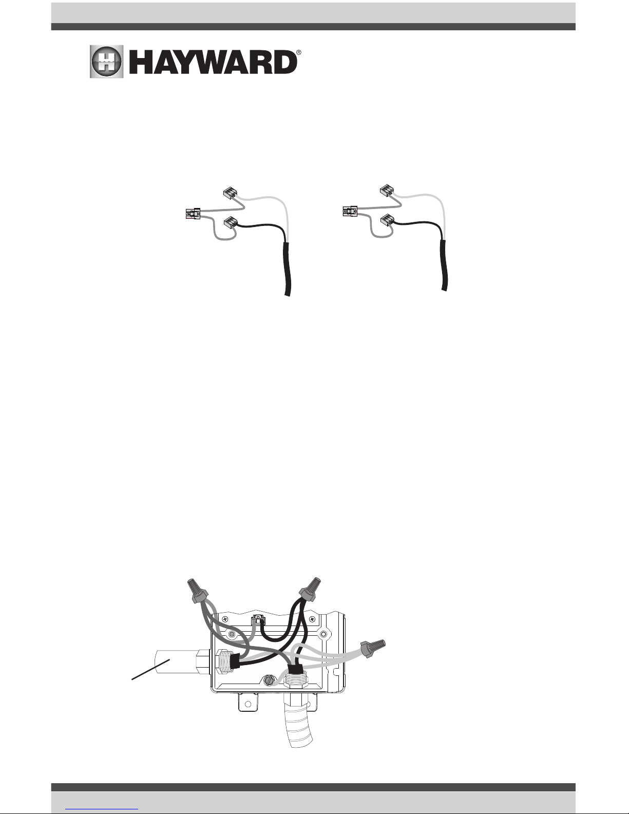
Temperature Sensors
Water Sensor
This sensor is used to measure the pool/spa temperature and is installed in the filtration plumbing
after the filter but before either the solar or conventionally fueled heaters.
1. Drill a 3/8” (10mm) diameter hole in the PVC piping and remove all chips and burrs.
2. Insert sensor until O-ring collar sits flush on the hole.
3. Position hose clamp over the sensor and gently tighten until O-ring makes an adequate seal.
Do not overtighten.
Air Sensor
Mount the air sensor outdoors. IMPORTANT: The air sensor must not be mounted in direct sunlight.
Solar Sensor
For solar applications, mount the sensor near the solar collector array so that it is exposed to the
same sunlight as the collectors. Use additional cable (20 AWG) if necessary.
Optional Valve Actuators
For installation, refer to the mounting instructions included with the Hayward GVA-24 actuator or
equivalent. After configuring and first operating the valve, note that the internal cams in the actuator
may have to be adjusted depending on the way the actuator is mounted on the valve and the desired
valve action.
Plumbing
Flow Switch
A Hayward GLX-FLO flow switch (sold separately) is required if an HL-CHEM ORP & pH Sensing Kit
will be used. If no chemistry equipment is installed, the GLX-FLO is optional and can be used to
detect leaks or clogs in your pool's plumbing system. If using the GLX-FLO, it must be plumbed in
line with any chemistry sensing/dispensing equipment at the very end of the return plumbing. This
will ensure that the OmniHub will detect a leak if it occurs anywhere at the pool pad. Understand that
if a leak occurs after the flow switch (downstream), the OmniHub will not sense a no-flow condition.
IMPORTANT: There must be at least a 12” (30cm) straight pipe run before (upstream) the flow switch.
IMPORTANT: To ensure proper operation, verify that the arrow on the flow switch points in the direction of water flow.
Filter Pump
If the OmniHub has been packaged with a filter pump, refer to the included pump manual for plumbing information.
USE ONLY HAYWARD GENUINE REPLACEMENT PARTS
10
Electrical Wiring
The Wiring Hub requires both high and low voltage connections. Always:
- Ensure that Power is disconnected prior to performing any wiring
- Follow all local and NEC (CEC if applicable) codes
- Use copper conductors only
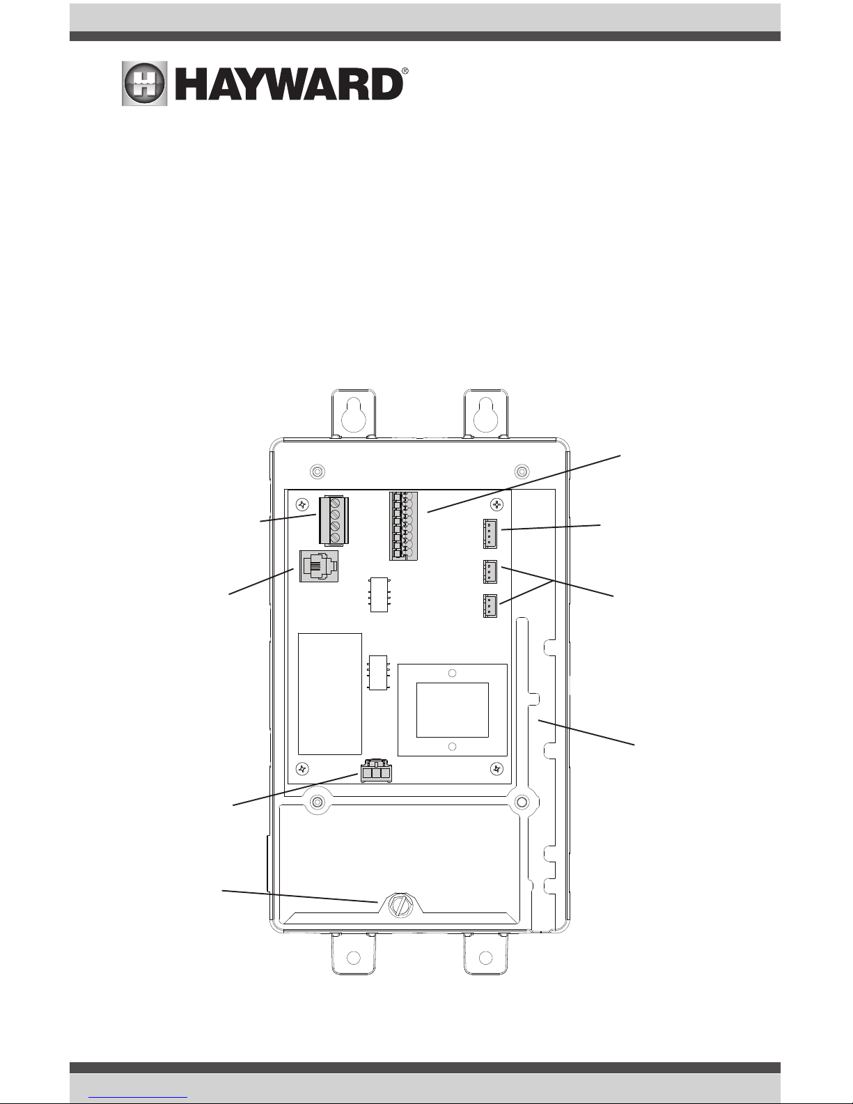
A dedicated channel on the right side of the Wiring Hub has been provided for all low voltage wiring.
All low voltage wires should run through this channel to exit the Wiring Hub. A weather resistant
gasket is provided (see page 23) to seal this exit.
Input Power
Flow Switch
Smart Relays, Variable
Speed Pumps, Sense
& Dispense, Aqua Rite
Communication
Temperature Sensors,
External Input
& Heater
Control Pad
Valve Actuators
Wiring Channel
Low Voltage
Ground Screw
Low Voltage
Channel
11
USE ONLY HAYWARD GENUINE REPLACEMENT PARTS
High Voltage Wiring
Hub Input Power
The Hub requires a constant 115 VAC or 230 VAC input power to operate. A wiring harness is included and will plug into the input power connector shown on page 11. Wire the harness according
to the diagram below.
Wiring Filter Pump Input Power
Note that Hayward supported variable speed pumps (VSPs) will connect to the OmniHub differently
than single speed (or two-speed) filter pumps. Single and two speed pumps are wired to Smart
Relays while VSPs are wired to a constant power source. The following information will show how to
wire both types. Refer to your filter pump's manual for the location of the input wiring terminals as
well as other related high voltage wiring information.
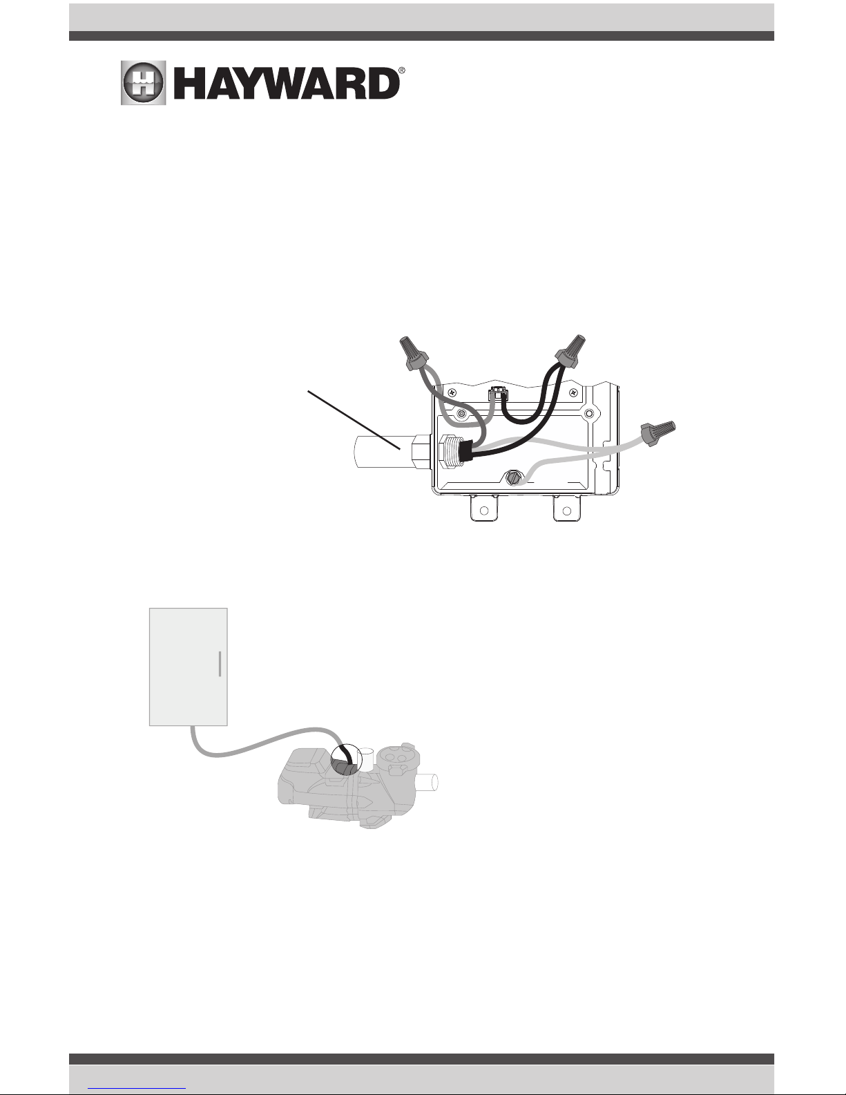
Powering Hub and VSP with Same Voltage
Variable speed filter pumps require constant power and are turned on and off through low voltage
communication wiring from the OmniHub. Because the OmniHub must also be powered continuously, it may be most convenient to wire the VSP and OmniHub in parallel, on the same circuit. If this
is the case, they must both be powered by the same voltage. An example of this is shown below.
As shown in Diagram 2 on page 6 and below, power can come from an existing timer, switch or an
electrical panel. Because both units need to be powered constantly, if power comes from a switch
or timeclock, set it to run continuously.
115 VAC
L1
N
230 VAC
L1
L2
Input Power from
existing timer, switch or
electrical panel
L1
L2 (230VAC)
or
N (115VAC)
Ground
Wiring Whip to VSP's
input wiring terminals
115 VAC or
230 VAC
Must be same for Pump and Hub
USE ONLY HAYWARD GENUINE REPLACEMENT PARTS
12
Powering Hub and VSP with Different Voltage
Wire the Hub and VSP separately if using different voltages for both. If the new pump requires a different voltage than the old, run a separate source from the electrical panel. The Hub, which can be
powered by either 115 VAC or 230 VAC, can be powered by the existing timeclock or switch. Both
units need power constantly so if there is a switch or timeclock in the system, it must be set to run
continuously.
Powering Hub and Single Speed Pump with Same Voltage
Single speed pumps require the use of Smart Relay(s). High voltage connections are made directly
to Smart Relays which are turned on and off through a low voltage communication connection to the
OmniHub. Like the OmniHub, Smart Relays can be powered by either 115 VAC or 230 VAC.
Connect 115 VAC from the
panel, timeclock, outlet or
switch. Make sure OmniHub is powered constantly.
Ground
115 VAC to Hub
Neutral
L1
230 VAC to VSP
Electrical Panel
Run separate
230 VAC constant source to
13
USE ONLY HAYWARD GENUINE REPLACEMENT PARTS
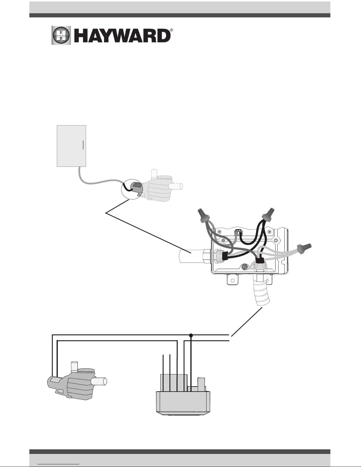
The example below shows a typical retrofit of the OmniHub into a system with an existing 115 VAC
filter pump. In this case, switched or timed input power to the pump is disconnected and distributed
to the input sides of both the OmniHub and a Smart Relay. Because the OmniHub and Smart Relays
require constant power, an existing timeclock or switch must be set to power both constantly. The
115 VAC pump is then wired to the output side of the Smart Relay.
Note that this connection method will work for 230 VAC, using the 230 VAC connections on the
Smart Relay.
Connect to Hub and
Smart Relay
L1
N (115VAC)
Ground
Disconnect from
existing 115 VAC
pump
Wiring Whip to
Smart Relay
115 VAC
Existing Timeclock
or Switch
Must be same for Hub and Pump
(wired through a Smart Relay)
Smart Relay
New 115 VAC
single speed pump
Connect to input side of
Smart Relay (see page
15)
Black/White
Gray
Black
Not Used
Not Used
Neutral
Line 1 in
Line 1 out
USE ONLY HAYWARD GENUINE REPLACEMENT PARTS
14
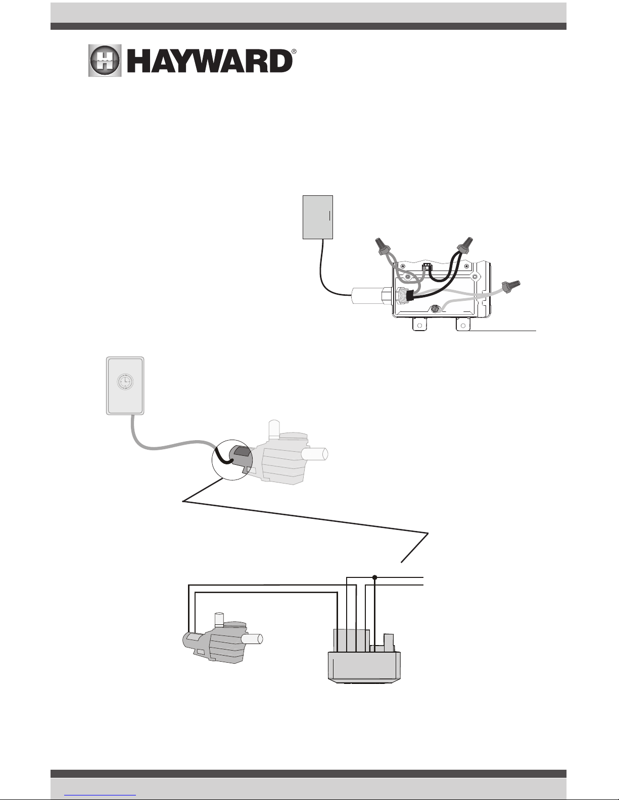
Powering Hub and a Single Speed Pump with Different Voltage
Example: The diagrams below show the Wiring Hub powered by 115 VAC directly from the electrical
panel. The existing 230 VAC wiring at the pump is disconnected and used to power the input side of
the Smart Relay. The output side of the Smart Relay is then wired to the pump.
Connect 230 VAC
directly to the input
side of the Smart
Relay
Disconnect 230 VAC
from existing pump
230 VAC to Smart Relay
Existing Timeclock,
Switch, Outlet or Panel
Smart Relay
Electrical Panel
Ground
L2
L1
115 VAC to Hub
Connect existing pump to 230
VAC output side of
Smart Relay
Black/White
Gray
Black
Red/White
Red
Line 2 in
Line 1 in
Line 1 out
Line 2 out
Input
Wiring
15
USE ONLY HAYWARD GENUINE REPLACEMENT PARTS
Grounding
Connect a ground wire from the primary electrical panel to the Wiring Hub's ground connection as
shown in the previous diagrams. Also ground each piece of high voltage equipment that is connected through the Wiring Hub or Smart Relay.
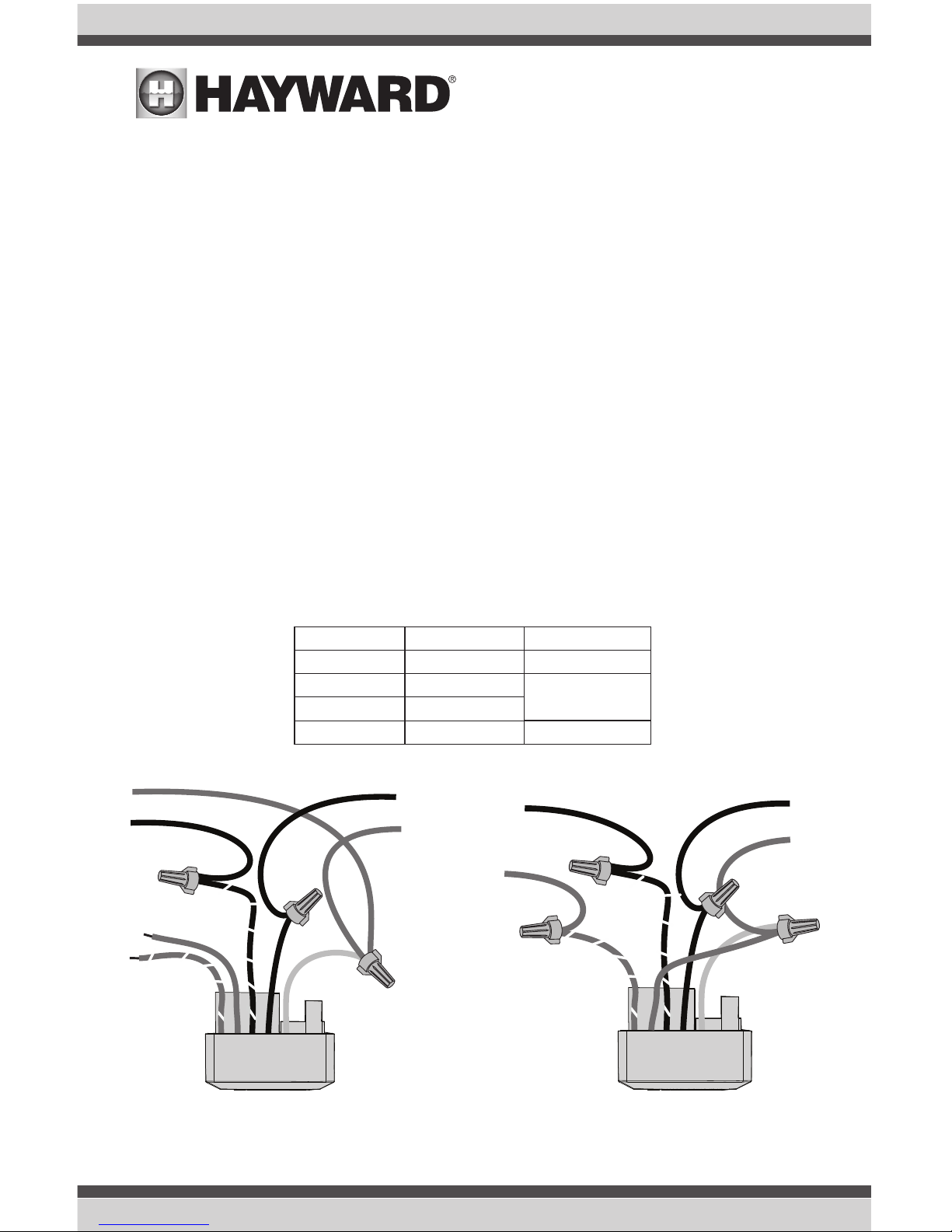
Smart Relay Load Wiring
A Smart Relay can be used to control either 115 or 230 VAC pool equipment. Previous diagrams
showed a Smart Relay connected filter pumps but other high voltage equipment like accessory water
feature pumps, lights, cleaners, transformers, etc. can be controlled as well.
Smart Relays can be installed into an existing electrical box with a minimum volume of 16.2 in3 or
with the box supplied with the OmniHub. Use the included Wiring Whip if the supplied electrical box
will be mounted within 6 ft of the power source. Red, black and green conductors are included
for 230 VAC wiring. A white conductor is supplied if using 115 VAC input power. Use the included
wire nuts for wiring connections. Use proper threaded strain relief fittings when attaching conduit
to knockouts. After wiring is complete, carefully insert the cover with connections into the box and
secure.
For accessory equipment, refer to the table and diagrams below.
Red
Red/White
Black
Black/White
Gray
Neutral
Load out
No Connection
No Connection
115 VAC
Load 2 out
Load 1 out
Line 1 in
230 VAC
Line in
Connect Gray &
Red to Line 2 in
Smart Relay
Wire Colors
Gray
Black
Black/White
Red
Red/White
Line 1 in
Neutral
Load 1 out
Neutral
Gray
Black
Black/White
Red
Red/White
Line 1 in
Line 2 in
Load 1 out
Load 2 out
230 VAC115 VAC
USE ONLY HAYWARD GENUINE REPLACEMENT PARTS
16
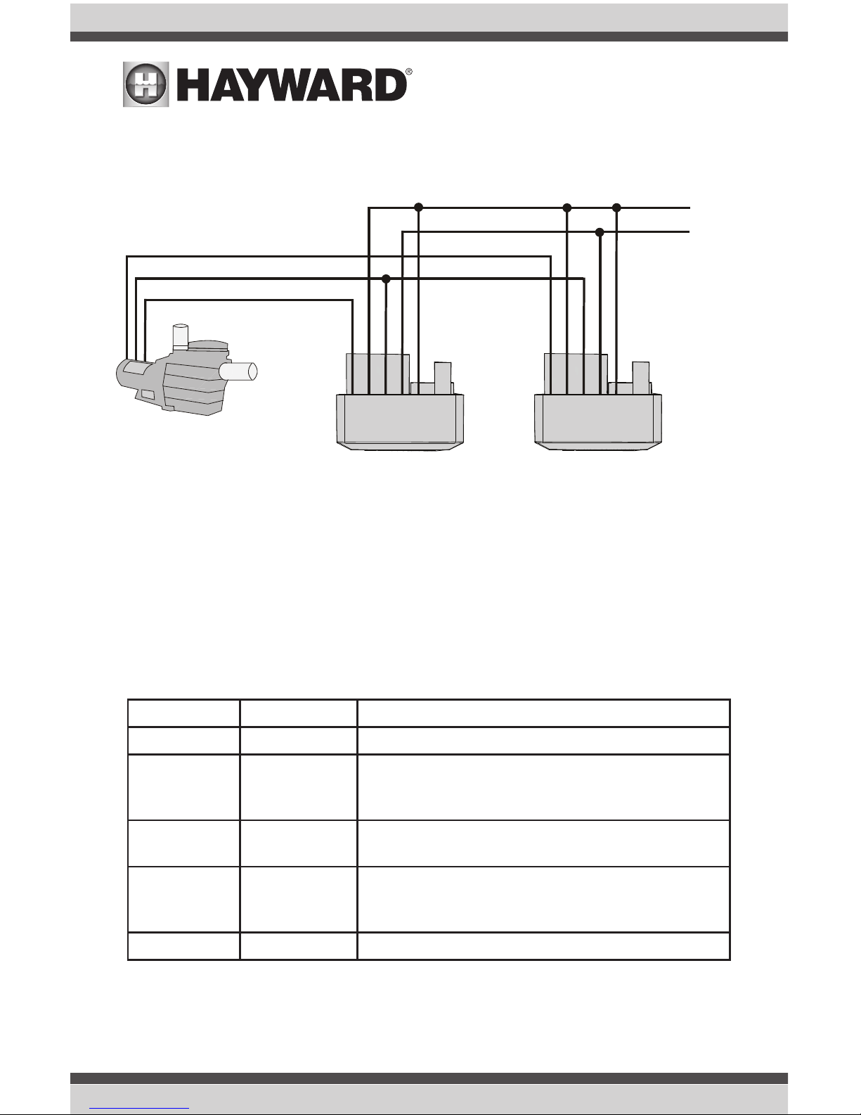
Black/White
Gray
Black
Red/White
Red
230 VAC
Two Speed
Line 2 in
Line 1 in
Common
Low Speed
Input
Wiring
Black/White
Gray
Black
Red/White
Red
Smart Relay 2
Smart Relay 1
High Speed
Powering a 230 VAC Two Speed Pump
A 230 VAC two speed pump requires the use of two Smart Relays. Refer to the diagram below.
Smart Relay LEDs and On/Off button
Although the Smart Relay will be automatically controlled by the Hub, it does feature a manual On/
Off button as well as two indicator LEDs. If communication has been interupted or lost to the Wiring
Hub, the Smart Relay's On/Off button will allow you to toggle back and forth between power states.
This button will not be functional during normal operation.
Refer to the table below when viewing the Smart Relay's indicator LEDs. Note that when the "Relay
On" LED is OFF, the relay is in an OFF state and there is no power going out to the load. When Green,
the relay is energized and the load receives power.
Remote LED Relay On LED Indication
Off Off No power or firmware failure
Red On for 1
sec, Off for 6
sec
Off or Green
There is no communication with the Wiring Hub - the
relay can be manually controlled using the On/Off
button
Green On Off or Green
There is communication with the Wiring Hub - this indi-
cates normal operation and On/Off button is disabled
Green 3 fast
blinks
Off or Green
User attempted to use the On/Off button manually
while the Smart Relay is being automatically controlled
by Wiring Hub (not allowed)
Blinking Blinking Firmware upgrade in progress
17
USE ONLY HAYWARD GENUINE REPLACEMENT PARTS
 Loading...