

Page 1
IS2001540LS-99
OWNER’S GUIDE
Your Micro Star-Clear cartridge filter has an output rating of 1400 gallons (5299 L) per hour.
The filter and pump are combined on a molded mounting base and are manufactured from
durable, corrosion-proof materials. The system is designed for installation below the pool
water line.
The Micro Star-Clear filter system utilizes a reusable single element, reinforced polyester
filter cartridge to provide a high degree of water clarity with absolute minimum care.
Removal of the cartridge for routine cleaning is fast and easy to do.
The SP1540 series Power-Flo LX pump is a non-corrosive centrifugal pump with pressure,
flow and operation designed for swimming pool service and may be operated on an intermittent or continuous basis.
SYSTEM LOCATION
Though the system is designed for outdoor use, it is
advisable to protect electrical components from the
weather. Select a well-drained area, one that will not
flood when it rains.
Position the system below the swimming pool water
line and as close to the pool as possible. Set the
mounting platform level. Allow a minimum clearance
for cartridge removal. Be sure the pipe connections,
drain, etc., are accessible for convenient operation
and cartridge removal.
TO ASSEMBLE THE SYSTEM
Place pump and motor on mounting base. Align holes
in motor base with holes in mounting base and secure
with two screws and washers provided.
Securely thread sweep elbow, with 3-4 wraps of
Teflon pipe tape, into outlet of pump. Position so that
large thread end points back toward the motor, at an
angle, toward corner of base.
Thread the ball end of union, with union nut, into
filter connection marked “IN.” Use Teflon tape (3-4
wraps on thread) and screw in as far as possible hand
tight, then one additional turn with a wrench.
Adjust ball and socket and join by hand tightening
union nut. Do not overtighten.
All plumbing connections on the system are 1-1/2”
N.P.T. When making connections, use plastic maleend adapters and flexible hose. Apply three turns of
Teflon tape or plastic pipe sealant to the male
threads. Screw the fitting into the thread hand tight;
then using a wrench, tighten one more full turn.
Additional tightening is unnecessary and could
result in damage to components.
NOTE: For extra convenience, you may wish to install
valves on the inlet and discharge of the system to
prevent back flow of water when removing cartridge.
See dealer for further information.
Connect the pool suction plumbing between the
skimmer pool outlet, and the pump. Connect the pool
return (inlet) plumbing.
A drain plug is furnished with each filter and is all
that is needed for complete filter draining. Amanual
air vent valve is furnished to aid in bleeding off
unwanted air when starting the filter.
All electrical connections must be made in
accordance with local codes.
Check for joint leaks before operating the system.
Refer to pump instruction booklet for pump
information.
BEFORE STARTING THE FILTER
Superchlorinate the pool water by adding unstabilized
granular or liquid chlorine. Stabilized forms of chlorine
are recommended for normal daily use after the initial
clean up of the water. Follow chemical manufacturer ’s
recommendations for superchlorination and daily use.
STARTING THE FILTER
Open manual air vent valve a few turns. CAUTION: All
suction and discharge valves must be open when
starting the system. Failure to do so could cause
severe personal injury and/or property damage.
Prime and start the pump following the manufacturer’s
instructions. Air trapped in the system will automatically
vent to the pool and out vent valve. Close vent valve as
soon as air is vented.
1.
2.
1.
2.
3.
4.
5.
6.
7.
8.
9.
10.
MODEL C2001540LS SERIES
Page 2
FILTERING
Filtration starts as soon as flow is steady through the
filter. As the filter cartridge removes dirt from the pool
water, the accumulated dirt causes a resistance to flow.
As a result, pressure will rise and the flow will decrease.
When flow decreases below desired rate, clean or replace
the filter cartridge.
CLEAN/REPLACE CARTRIDGE
Removing Cartridge Element
Shut off the pump.
Block off suction and discharge lines (close valves if
used) to prevent back flow of water from pool.
Open top air relief valve and remove drain valve to
allow water to drain from filter.
Unscrew union nut, freeing filter from rigid union
connection.
Hold filter head firmly and unscrew filter housing to
remove. If difficult to unscrew, apply a lever between
the two tab extensions on the bottom of the filter
housing and apply a slight pressure to assist in
freeing the thread seal. Or, apply optional S200KT
wrench (if supplied) to bottom side tabs.
Remove cartridge element and clean. Or, replace
with clean, spare cartridge. (See Cleaning Cartridge)
1.
2.
3.
4.
5.
6.
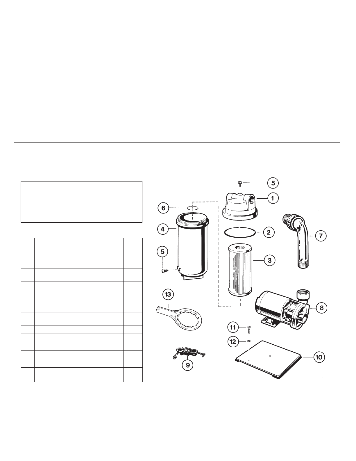
PARTS
Model C2001540LS
1
2
3
4
5
6
7
8
9
10
11
12
13
1
1
1
1
2
1
1
1
1
1
2
2
---
CX120AA
CX120D
CX200RE
CX120B
ECX1321A
SPX1485C
SPX14858PAK
SP1540CLS
SPX1500WA
ECX12891
ECX1108
ECX1109
S200KT
Filter Head
O-Ring
Cartridge Element -
20 sq. ft.
Filter Body Housing
Air Relief Valve
with O-Ring
Gasket
Threaded Elbow
Union Assembly
Power-Flo LX Pump
6 Ft. Cord Set
Mounting Base
Mounting Screw
Washer
Wrench Tool for Body
(optional)
PART NO.
DESCRIPTION
REF.
NO
NO.
REQ’D.
NOTE; ANSI/NSPI-4 Article V, standard for above-ground and on-ground pools,
advises that components such as the filtration system, pumps and heater be
positioned so as to prevent their being used as a means of access to the pool
by young children.
Page 3

Reinstalling Cartridge Element
Clean any collected debris from the bottom of the
filter housing.
Reinstall cartridge in filter housing. Be sure O-ring is
in place on threads.
Clean O-ring. For ease of future disassembly, apply a
very light film of a dilute solution of non-granulated
liquid-type soap to O-ring and threads.
Screw filter housing with O-ring into filter head. Do
not overtighten. Tighten drain valve and top air relief
valve.
Secure to system with union nut.
Proceed as in Starting the Filter.
Cleaning Cartridge
The cartridge filter element can be cleaned by pressure
washing inside and out with a garden hose. Rotate
cartridge, hosing from top down. (The cartridge is easier
to clean when dry). After hosing the cartridge, for best
results, allow cartridge to dry and carefully brush
pleated surface areas to remove fine particles.
Algae, suntan oil and body oils can form a coating on the
cartridge pleats which may not be thoroughly removed by
hosing. To remove such materials, soak the cartridge in a
solution of filter element cleaner (various brands available
at pool dealer). Follow manufacturer ’s directions for use
and allow an hour for soaking. Hose thoroughly before
reinstalling in filter.
If calcium or mineral deposits are excessive, the cartridge
may be restored to “like new” condition by soaking in
muriatic acid. Use commercially available 20% muriatic
acid added to water in 1 to 1 ratio. Use a plastic container
and take extreme care when handling cleaning agents as
they can be harmful to eyes, skin and clothing. After
cleaning, flush with water.
VACUUMING
Vacuuming can be performed directly into the filter
whenever needed. Clean cartridge after vacuuming, if
required.
WINTERIZING
In areas where sub-freezing temperatures can be
expected, the filter should be drained and/or removed
from its operating location and stored indoors. Remove
and clean cartridge. Reinstall cartridge in filter tank.
Tighten cover only a few turns when storing.
SERVICE & REPAIRS
Consult your local and authorized Hayward dealer or
service center. No returns may be made directly to the
factory without the expressed written authorization of
Hayward Pool Products, Inc.
1.
2.
3.
4.
5.
6.
ALGAE CONTROL
Algae is a form of plant life which can vary in size from a
few thousandths of an inch to the size of a small tree. Of
the many forms of algae, those most frequently found in
swimming pool water are microscopic in size and green in
color .
Algae readily grows in sunlight and can, under favorable
conditions, quickly overgrow a swimming pool turning it
completely green in just a few hours. On the other hand,
swimming pool water can be kept unfavorable to algae
growth simply by maintaining a chlorine level of at least
1.0 ppm in the water at all times. The chlorine level
should be checked at least once a day using a suitable test
kit.
If an algae condition develops and the pool water
“blooms” green, superchlorination of the pool will be
necessary to clear it. Add unstabilized granular chlorine,
or liquid chlorine. Follow chemical manufacturer’s
recommendation for superchlorination. The algae will
quickly become inactive and can then be removed by the
filter. Live algae, on the other hand, multiplies so fast,
that the filter cannot keep up with its growth rate.
When correctly used, commercial algaecides are effective
against algae, though algaecides should be used in
conjunction with, and not as a substitute for, regular
chlorination or superchlorination.
Maintaining a chlorine level of at least 1.0 ppm in the
pool water at all times is the most effective way to
prevent algae growth in swimming pools.
POOL CHEMISTRY GUIDELINES
ACTION REQUIRED TO CORRECT POOL CHEMISTRY
TO RAISE
TO LOWER
SUGGESTED POOL CHEMISTRY LEVELS
pH
TOTAL ALKALINITY
CHLORINE (UNSTABILIZED)
CHLORINE (STABILIZED)
CHLORINE STABILIZER
(Cyanuric Acid)
7.2 to 7.6
100 to 130 ppm
0.3 to 1.0 ppm
1.0 to 3.0 ppm
40 to 70 ppm
Add Soda Ash
Add Sodium Bicarbonate
Add Chlorine Chemical
Add Chlorine Chemical
Add Stabilizer
Add Muriatic Acid or Sodium Bisulphate
Add Muriatic Acid
No action - chlorine will naturally dissipate
No action - chlorine will naturally dissipate
Dilution - partially drain & refill pool with water
that has not been treated with Cyanuric Acid.
Page 4

© 1999 Hayward Printed in U.S.A.
Rev. 4/99 A
 Loading...