

Hayward ENP1M, ENP4M, ENP2M, ENP3M, ENP5M Installation Instructions Manual
...
ENERGYLINE PRO
SWIMMING POOL HEAT PUMP UNIT
Installation & Instruction Manual

CONTENTS
1. Preface 1
2. Specifications 2
2.1 Technical data for the swimming pool heat pump unit 2
2.2 Operating range 3
2.3 Dimensions 4
3. Installation and connection 5
3.1 Functional diagram 5
3.2 Heat pump unit 6
3.3 Hydraulic connection 6
3.4 Electrical connection 7
3.5 Initial start-up 8
3.6 Water flow setting 10
4. User interface 11
4.1 Overview 11
4.2 Clock function/settings 13
4.3 Tuner function/settings 13
4.4 Operation mode selection: heating or
cooling 14
4.5 Setting and visualisation for the set point 15
4.6 Locking and unlocking the touch screen 15
5. Maintenance and Winterising 16
5.1 Maintenance 16
5.2 Winterising 16
6. Appendix 17
6.1 Electrical Diagrams 17
6.2 Heating priority wiring 22
6.3 Exploded view and spare parts 24
6.4 Troubleshooting guide 34
6.5 Warranty 35
Please read attentively and save for future consultation.
This document must be given to the pool owner and should be kept in a safe place.

1. PREFACE
We thank you for purchasing this Hayward swimming pool heat pump unit.
This product was designed according to strict manufacturing standards to
satisfy the required quality levels. This manual includes all of the necessary
information concerning installation, debugging and maintenance. Please
attentively read this manual before opening the unit or before carrying out
any maintenance operations on it. The manufacturer of this product will not,
under any circumstances, be held responsible in the case of injury to the
user or damage to the unit resulting from improper installation, debugging
or unnecessary maintenance. It is essential to follow all of the instructions
specified in the manual at all times. The unit must be installed by a qualified
professional.
• Repairs must be made by a qualified professional.
• All electrical connections must be made by a qualified electrician according
to standards in the country of installation see § 3.4.
• Maintenance and the different operations must be carried out at the
recommended times and frequencies as specified in this manual.
• Only use genuine spare parts.
• Failure to comply with these recommendations will invalidate the warranty.
• This swimming pool heat pump unit heats swimming pool water and
maintains a constant temperature; it should not be used for any other
purpose.
After having read this manual, keep it for future usage.
Warnings concerning children/people with reduced physical capacity:
This appliance is not intended to be used by persons (especially children)
with reduced physical, sensory or mental capabilities or by persons who lack
experience or knowledge, unless they are under supervision or have received
instructions concerning the use of the appliance by a person responsible for
their safety.
This product contains greenhouse effect fluorinated gases covered by the
Kyoto protocol.
Type of refrigerant: R410A
(1)
GAP Value
: 1975
Periodic inspections for refrigerant leakage can be required as a function
of European or local legislation. Please contact your local distributor for
additional information.
(1) Potential for global warming
1

2. SPECIFICATIONS
2.1 Technical data for the swimming pool heat pump unit
17
15
12.5
17.5
15
12,5
11
7,9
58058
51225
42690
59765
51225
42690
37570
27000
3 / 50Hz
380 V
3 / 50Hz
380 V
3 / 50Hz
380 V
1 / 50Hz
230 V
1 / 50Hz
230 V
1 / 50Hz
230 V
1 / 50Hz
230 V
1 / 50Hz
230 V
875
1140/470/
875
1140/470/
875
1140/470/
875
1140/470/
875
1140/470/
875
1140/470/
875
1140/470/
660
1025/455/
980
1240/500/
980
1240/500/
980
1240/500/
980
1240/500/
980
1240/500/
980
1240/500/
980
1240/500/
760
1130/470/
Absorbed electrical power kW 1,4 1,8 2,4 2,9 3,4 3,8 2,85 3,3 3,6
230 V
V
Running current* A 6,4 8,2 11,3 13,1 14,9 17,3 5,7 6,1 7,1
1 / 50Hz
Ph/Hz
aM type fuse calibre A 10 aM 12 aM 16 aM 20 aM 25 aM 30aM 10aM 10aM 12aM
Curve D circuit breaker A 10 D 12 D 16 D 20 D 25 D 30D 10D 10D 12D
Power supply
660
760
1025/455/
1130/470/
/h 2,5 3,4 5 5,2 6 7 5,1 6,2 7
3
Water pressure drop
Hydraulic connection mm 50 50 50 50 50 50 50 50 50
Nominal water flow* m
kPa 10 10 12 12 12 17 12 12 17
(max)
Unit net dimensions (L/l/h) mm
dB(A) 51 54 56 56 56 56 56 56 56
Compressor quantity 1 1 1 1 1 1 1 1 1
Type of compressor Rotary Rotary Rotary Scroll Scroll Scroll Scroll Scroll Scroll
Fan quantity 1 1 1 1 1 1 1 1 1
Fan power W 120 120 150 150 150 150 150 150 150
Fan rotation speed RPM 850 850 850 850 850 850 850 850 850
Ventilation Horizontal Horizontal Horizontal Horizontal Horizontal Horizontal Horizontal Horizontal Horizontal
Sound pressure level
(at 1 metre)
kg 57/71 61/75 80/98 106/124 106/124 110/125 106/124 106/124 110/125
mm
Unit shipping dimensions
(L/l/h)
Net weight / shipping
weight
* Value at +/- 5% under the following conditions: Exterior temperature = 15°C (59°F) / HR = 71% / Water inflow temperature = 26°C (78.8°F) / ∆T water 2°C (3.6°F).
According to the NF 414 standard.
ENP1M ENP2M ENP3M ENP4M ENP5M ENP6M ENP4T ENP5T ENP6T
PRO
ENERGYLINE
Models
5,9
20140
kW
BTU/h
Heating capacity*
2
2. SPECIFICATIONS (continued)
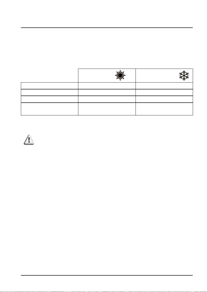
2.2 Operating range
Use the swimming pool heat pump unit within the following ranges of
temperature and humidity to ensure safe and efficient operation.
Heating mode Cooling mode
Outside temperature +2°C ~ +35°C +7°C ~ +43°C
Water temperature +12°C ~ +40°C +8°C ~ +40°C
Relative humidity < 80% < 80%
Setting range from the set
point
If the temperature or humidity does not correspond to these conditions,
the security measures could be activated and the swimming pool heat
pump unit may no longer work.
+15°C ~ +40°C +8°C ~ +35°C
3
2. SPECIFICATIONS (continued)
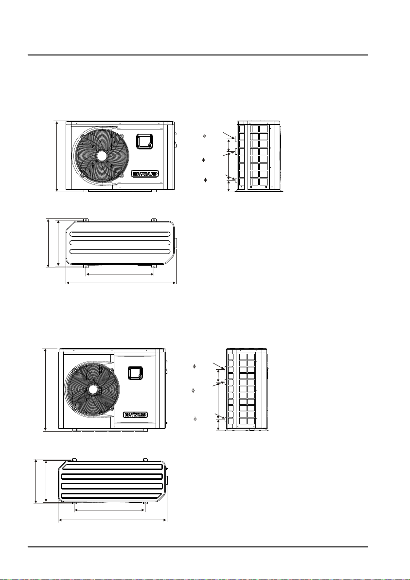
2.3 Dimensions
Models: ENP1M/ENP2M Unit: mm
Water inlet
50
66 0
Water outlet
Drainage
Frontal view
45 5
43 0
630
1025
Overhead view
Models: ENP3M/ENP4M/ENP5M Unit: mm
ENP4T/ENP5T/ENP6M/ENP6T
12 0
50
27 0
25
82
Water inlet
50
87 5
Water outlet
Drainage
47 0
43 0
740
1140
12 0
50
40 0
25
82
4
3. INSTALLATION AND CONNECTION
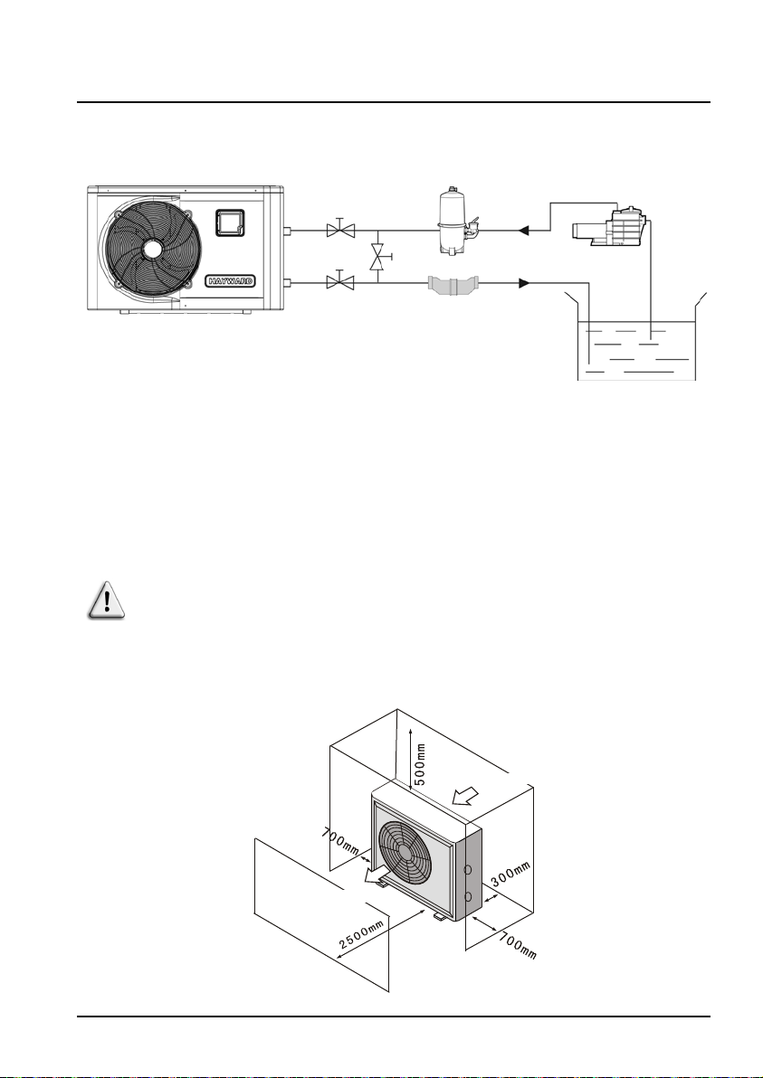
3.1 Functional Diagram
Water Inlet
valve
Water outlet
valve
By-pass
valve
Chlorinator cell
(or other treatment)
Filter
Water outlet
Pump
filtration
Pool
Note: The swimming pool heat pump unit is sold without any treatment or
filtration equipment. The components presented in the diagram are
spare parts to be supplied by the installer.
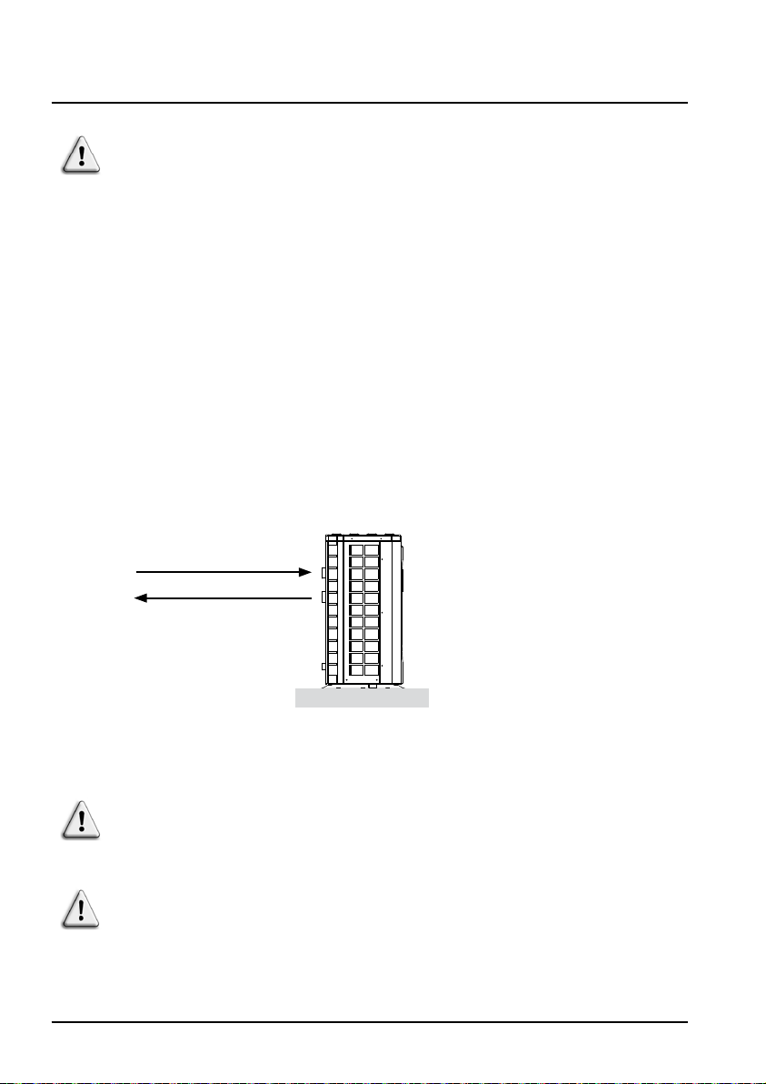
3.2 Heat pump
Place the heat pump outdoors and away from any enclosed technical
space.
Placed under a shelter, the minimum required distances mentioned
below must be respected in order to avoid any risk of air recirculation
and a deficiency in the unit's overall performance.
Air evacuation
Air intake
5
3. INSTALLATION AND CONNECTION (continued)
It is advised to install the unit on a dissociated cement block or a
mounting bracket designed for this use and to set up the unit on the
supplied rubber bushing (fastenings and washers not supplied).
The maximum installation distance between the unit and the swimming
pool is 15 metres.
The total length of the piping to and from the unit is 30 metres.
Insulate both the above ground and buried hydraulic piping.
3.3 Hydraulic connection
The unit is supplied with two 50 mm Ø union connections. Connect the water
inlet to the heat pump coming from the filtration group then connect the water
outlet to the heat pump at the water conduit going to the pool (see diagram
below).
of the filter Ø 50 ENTRY H2O
to the pool Ø 50 EXIT H2O
Install a by-pass valve between the heat pump entrance and exit.
If an automatic distributor or an electrolyser is used, it should be
installed imperatively after the heat pump with the goal of protecting the
titanium condenser against an elevated concentration of chemicals.
Be sure to install the by-pass valve and the supplied union connections
at the water inlet and outlet level in order to simplify purging during
the winter period and to facilitate access when disassembling for
maintenance.
6
3. INSTALLATION AND CONNECTION (continued)
3.4 Electrical connection
Electrical installation and wiring for this equipment must be in
conformity with local installation standards.
F NF C15-100 GB BS7671:1992
D DIN VDE 0100-702 EW EVHS-HD 384-7-702
A ÖVE 8001-4-702 H MSZ 2364-702/1994/MSZ 10-553 1/1990
E UNE 20460-7-702 1993,
RECBT ITC-BT-31 2002
IRL Wiring Rules + IS HD 384-7-702 PL PN-IEC 60364-7-702:1999
I CEI 64-8/7 CZ CSN 33 2000 7-702
LUX 384-7.702 S2 SK STN 33 2000-7-702
NL NEN 1010-7-702 SLO SIST HD 384-7-702.S2
P RSIUEE TR TS IEC 60364-7-702
Verify that the available electrical power supply and the network
frequency correspond to the required operating current taking into
account the appliance's specific location, and the current required to
supply any other appliance connected to the same circuit.
ENP 1M 230 V~ +/- 10% 50 HZ 1 Phase
ENP 2M 230 V~ +/- 10% 50 HZ 1 Phase
ENP 3M 230 V~ +/- 10% 50 HZ 1 Phase
ENP 4M 230 V~ +/- 10% 50 HZ 1 Phase
ENP 5M 230 V~ +/- 10% 50 HZ 1 Phase
ENP 6M 230 V~ +/- 10 % 50 HZ 1 Phase
ENP 4T 380 V~ +/- 10 % 50 HZ 3 Phases
ENP 5T 380 V~ +/- 10 % 50 HZ 3 Phases
ENP 6T 380 V~ +/- 10 % 50 HZ 3 Phases
See the corresponding wiring diagram in the appendix.
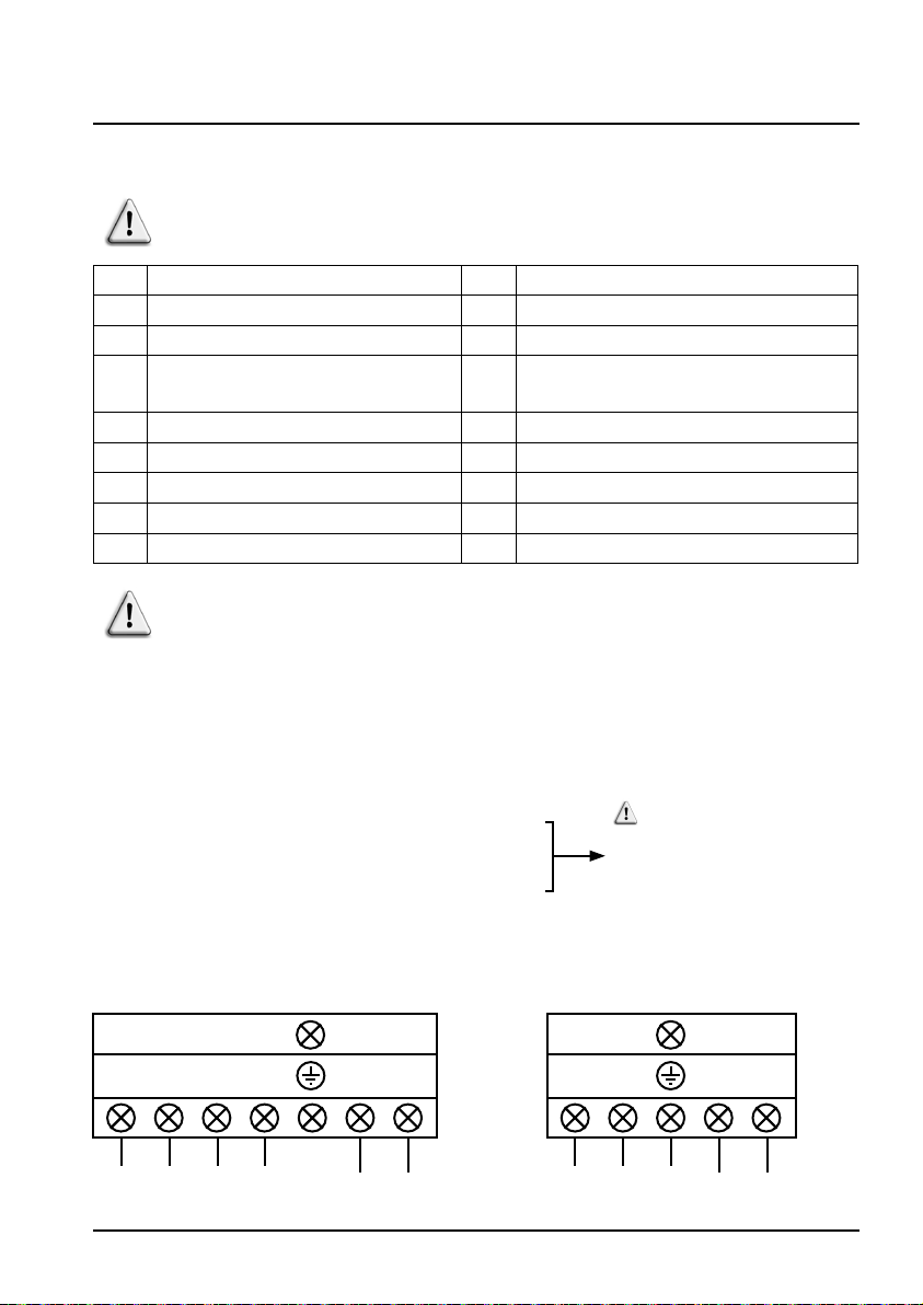
The connection box is located on the right side of the unit. Three
connections are designed for the power supply and two are for
controlling the filter pump (Enslavement).
M MSA HD 384-7-702.S2
Check that the phases
balance does not exceed 2%
= = = =
R S T N
Power supply
380V~ / 50Hz
==
1 2
Output 230V~
Enslavement filtration
pump 20A max
= = = =
L N 1 2
Power supply
230V~ / 50Hz
Output 230V~
Enslavement filtration
pump 20A max
7
3. INSTALLATION AND CONNECTION (continued)
The electrical power supply must have, when appropriate, a fuse
protection device like a feed motor (aM) or D curve circuit breaker as
well as a differential circuit breaker 30mA (see following table).
Models ENP1M ENP2M ENP3M ENP4M ENP5M ENP6M ENP4T ENP5T ENP6T
Power supply V/Ph/Hz
aM type fuse
calibre
Curve D circuit
breaker
230 V~
1/50 Hz
A 10 aM 12 aM 16 aM 20 aM 25 aM 30 aM 10 aM 10 aM 12 aM
A 10 D 12 D 16 D 20 D 25 D 30 D 10 D 10 D 12 D
Always shut down the main power supply before opening the electrical
control box.
3.5 Initial start-up
Start-up procedure - After installation is complete, follow these steps:
1) Rotate the fan by hand to verify that it can turn freely, and that the turbine
is correctly affixed to the motor shaft.
2) Ensure that the unit is connected correctly to the main power supply (see
the wiring diagram in the appendix).
3) Activate the filtration pump.
4) Verify that all water valves are open and that the water flows toward the
unit before switching on the heating or cooling mode.
5) Verify that the drainage hose is correctly affixed and that it causes no
obstructions.
6) Activate the unit power supply, then press the On/Off button
control panel.
7) Ensure that no ALARM code is displayed when the unit is ON (see
troubleshooting guide).
230 V~
1/50 Hz
230 V~
1/50 Hz
230 V~
1/50 Hz
230 V~
1/50 Hz
230 V~
1/50 Hz
380 V~
3/50 Hz
380 V~
3/50 Hz
on the
380 V~
3/50 Hz
8
3. INSTALLATION AND CONNECTION (continued)
8) Set the water flow using the by-pass valve (see § 3.6 and 2.1), as
provided for by each model, to obtain an Entry/Exit temperature of 2°C.
9) After running for several minutes, verify that the air exiting the unit is cool
(between 5 and 10°).
10) With the unit operating, turn off the filter pump. The unit should
automatically turn off and display error code E03.
11) Allow the unit and the pool pump to run 24 hours per day until the
desired water temperature has been reached. When the set water inlet
temperature is reached, the unit will turn off. It will automatically restart (as
long as the pool pump is running) if the pool temperature is at least 0.5°C
below the set temperature.
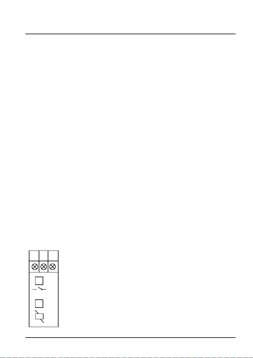
Water flow switch - The unit is equipped with a flow switch that turns on the
heat pump when the pool filtration pump is running, and deactivates it when
the filtration pump is out of order. If the water is low, the E03 alarm code will
appear on the regulator (See § 6.4).
Time delay - The unit is equipped with a time delay of 3 minutes in order
to protect the control circuit components, to eliminate restart cycling and
contactor chatter. Thanks to this time delay, the unit automatically restarts
approximately 3 minutes after each control circuit interruption. Even a brief
power interruption will activate the restart time delay.
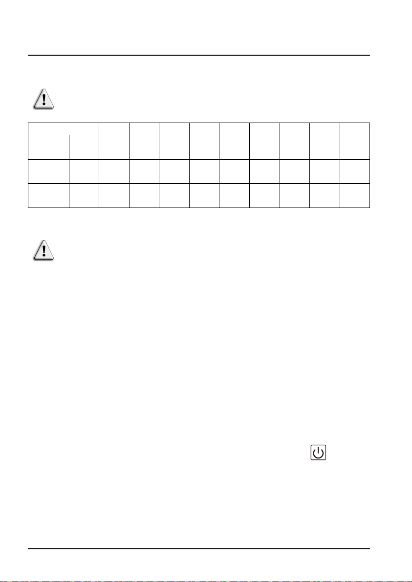
Phase switch - The Triphasic units include a phase switch to ensure that the
compressor is rotating in the correct direction. If the unit does not start, check
the condition of the phase switch located in the electrical box.
L1 L2 L3
4 Yellow/orange ON = Relay ON = Order and Phase number OK
4 Green = Power on
9

3. INSTALLATION AND CONNECTION (continued)
3.6 Water flow setting
With the water entry and exit valves being open, adjust the by-pass valve in
order to obtain a difference of 2°C between the inflow and outflow temperature
(see principle diagram § 3.1). You can verify the switch by seeing the entry/
exit temperatures directly on the control panel.
Water inlet temperature
Water outlet
temperature
Note: Opening the by-pass valve creates a weaker flow, which leads to an
increasein∆T.
Closing the by-pass valve creates a stronger flow, which leads to a
decreasein∆T.
10
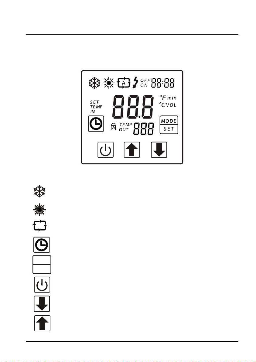
4. USER INTERFACE
4.1 General presentation
The heat pump is equipped with a digital control panel with a touch screen,
electronically connected and pre-set at the factory in heating mode.
Key
Symbol Cooling Mode
A
MO DE
S E T
Symbol Heating Mode
Automatic mode
Clock and timer settings
Selection and settings button
On/Off button and return
Scroll down
Scroll up
11
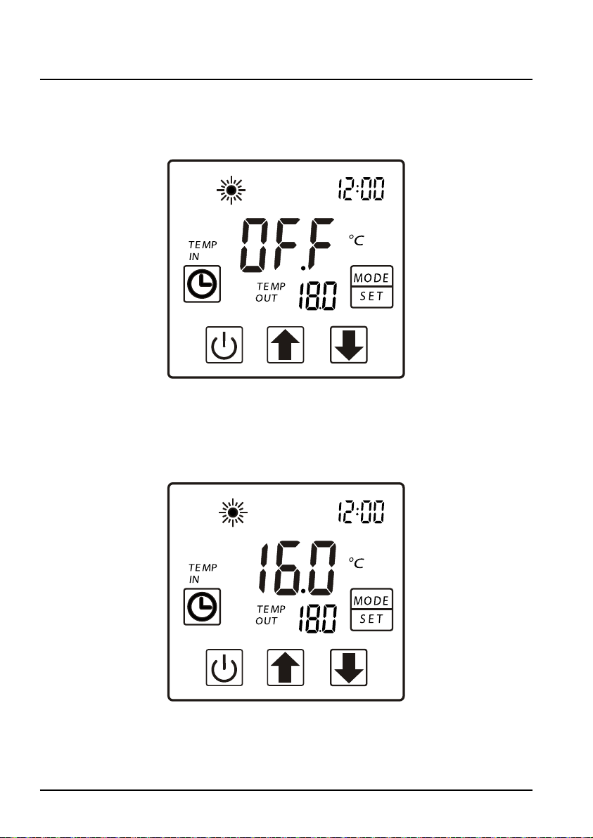
4. USER INTERFACE (continued)
OFF Mode
When the heating pump is in sleep mode (OFF Mode) “OFF” is displayed on
the command screen.
ON Mode
When the heating pump is running or regulating (ON Mode), the inlet and
outlet water temperatures are displayed on the command screen.
12
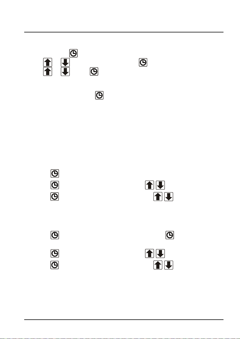
4. USER INTERFACE (continued)
4.2 Clock settings
Press 2 times on , the blinking time display then set the time with the
arrows or then press one more time to set the minutes with the
arrows or . Press to validate.
Note: The settings will be automatically saved if no button is pressed after 5
seconds, if not press
4.3 Timer function settings
Setting this function is necessary if you would like to run the heat pump for
a shorter period than what is defined by the filtration clock. Therefore, you
can program a deferred start and an anticipated stop or simply stop a certain
timeframe from running (at night, for example).
Start Program (Timer ON) / Start
to validate.
1) Press
2) Press
3) Press
It is automatically saved after 5 seconds of no action.
Stop Program (Timer OFF) / Stop
1) Press
until timer "OFF" blinks.
2) Press
3) Press
2 seconds, Timer “ON” blinks.
to set the hour using the buttons .
to set the minutes using the buttons .
2 seconds, Timer “ON” blinks then press 3 times in a row
to set the hour using the buttons .
to set the minutes using the buttons .
13
 Loading...