

Page 1
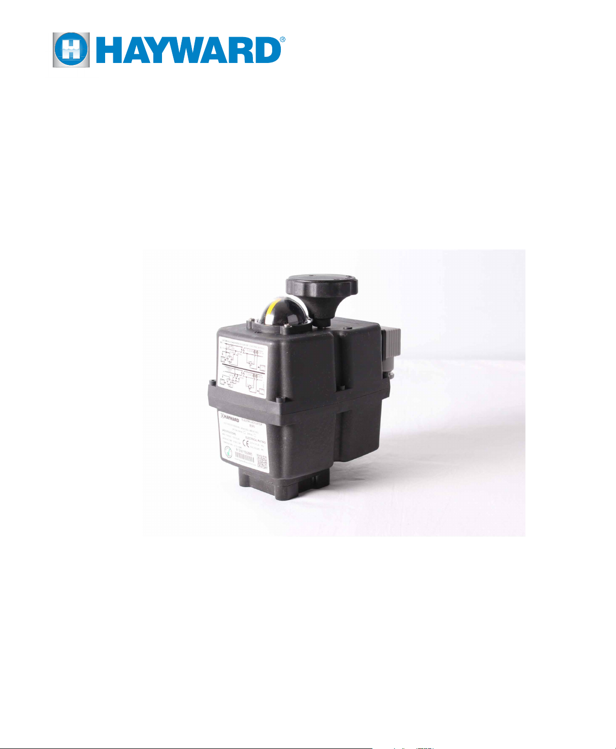
INSTALLATION, OPERATION AND
MAINTENANCE INSTRUCTIONS
ECP3, ECP5, ECP8 Series Actuators
TO PREVENT POTENTIAL INJURY OR DAMAGE TO PROPERTY, READ THIS MANUAL CAREFULLY AND COMPLETELY.
Page 2
IMPORTANT SAFETY INSTRUCTIONS
Basic safety precautions should always be followed, including the following: Failure to follow instructions
can cause severe injury and/or death.
This is the safety-alert symbol. When you see this symbol on your equipment or in this manual, look
for one of the following signal words and be alert to the potential for personal injury.
WARNING warns about hazards that could cause serious personal injury, death or major property
damage and if ignored presents a potential hazard.
CAUTION warns about hazards that will or can cause minor or moderate personal injury and/or
property damage and if ignored presents a potential hazard. It can also make consumers aware of
actions that are unpredictable and unsafe.
Notice:
A notice indicates special instructions that are important but not related to hazards.
WARNING - Read and follow all instructions in this IOM manual and on the equipment. Failure
to follow instructions can cause severe injury and/or death.
WARNING – Risk of Electric Shock. All electrical wiring MUST be in conformance with applicable
local codes, regulations, and the National Electric Code (NEC). Hazardous voltage can shock, burn,
and cause death or serious property damage. To reduce the risk of electric shock, do NOT use an
extension cord to connect unit to electric supply. Provide a properly located electrical receptacle.
Before working on any electrical equipment, turn off power supply to the equipment.
WARNING – To reduce the risk of electric shock replace damaged wiring immediately.
WARNING – Ground all electrical equipment before connecting to electrical power supply.
Failure to ground all electrical equipment can cause serious or fatal electrical shock hazard.
WARNING – Do NOT ground to a gas supply line.
WARNING – To avoid dangerous or fatal electrical shock, turn OFF power to all electrical
equipment before working on electrical connections.
WARNING – Failure to bond all electrical equipment to system structure will increase risk for
electrocution and could result in injury or death. To reduce the risk of electric shock, see installation
instructions and consult a professional electrician on how to bond all electrical equipment. Also,
contact a licensed electrician for information on local electrical codes for bonding requirements.
CAUTION – Potential pinch point. Equipment connected to or driven by this device may start
unexpectedly and may cause personal injury or entrapment in linkage systems.
Page 3

TABLE OF CONTENTS
ECP Series
Important Safety Instructions .....................2
Table of Contents ...............................3
ECP Series Operational Concepts ..............3
Technical Information ...........................4
Wire Sizing Chart ...............................4
ECP Component Identication ....................5
Quick Reference Guide ..........................6
Actuator Handling And Installation .................7
Shipping and Handling .......................7
Installation Notes ............................7
Product Mounting And Setup ..................8
Operational Status LED .......................9
On/Off Control ................................10
Wiring Diagram ............................10
Calibration And Commissioning ..................11
On/Off Control .............................11
Proportional Controller .........................12
PC Option - External Self-Adjustment ..........13
Wiring Diagram ............................13
PC Option - Controller Setup .................14
Calibration And Commissioning ..................15
Proportional Control ........................15
BB Battery Backup ..............................16
Setup For Fail CW/CCW ......................16
Disassembly / Assembly ..........................17
Adjusting CW End of Travel .......................18
Adjusting CCW End of Travel ......................19
Troubleshooting .................................20
Mechanical Data ................................21
Model: ECP3 ................................21
Model: ECP5 ................................21
Model: ECP8 ................................22
Internal Component Details .......................22
ECP3, ECP5 & ECP8 ..........................22
Motor Power Consumption ........................23
ECP SERIES OPERATIONAL CONCEPTS
ECP Series multivoltage electric actuators are motor powered, gear driven actuators for valves, dampers, and
other applications. They can be used with any power supply 24VAC/VDC – 240VAC and feature manual override
handwheels, easily visible position indicators, and a status LED.
All ECP Series actuators rotate CW to CLOSE the OUTPUT shaft out the bottom of the actuator when viewed
from ABOVE. This includes the direction of rotation of the internal cam shaft when viewing with the cover and
indicator removed.
All ECP Series actuators are designed to rotate between 0° and 90° (standard) or between 0° and 180° (option). When
using the manual override system, be sure the yellow position indicator is situated in the correct quadrant before
returning to automatic operation to prevent erratic operation of the actuator under power (see page 6).
Available options for the ECP Series include: Proportional Control with digital feedback, Battery Backup, or Rotation
Options (0°–45°, 0°–90°, 0°–180°). Not all options are available in all combinations for all products in the series.
This IOM is supplied with ECP Series actuators that may have been shipped separately or as an assembly of the
actuator and a Hayward ball or buttery valve. If this actuator was provided as part of the Hayward assembly, a
separate IOM for the valve should be included in your shipment.
Notice: ECP Series actuators are fully assembled, calibrated and tested prior to leaving our factory. In most cases, after
you have mounted the actuator to your device, you should be able to operate the actuator from fully CLOSED (CW) to fully
OPEN (CCW) and back again, and nd that no adjustments are needed. The assembly can be put into service immediately
and should afford the end user years of service without incident. However, should it be necessary to make adjustments to
the end-of-travel positions to overcome any device related issues (i.e. valve shaft incorrectly timed to the drive stem), the
procedures outlined on the page numbers referenced below should be followed to put the assembly into service.
Pages 18-19 - Travel limits and Auxiliary switch cams for CW (CLOSED) & CCW (OPEN) positions
Page 4
TECHNICAL INFORMATION
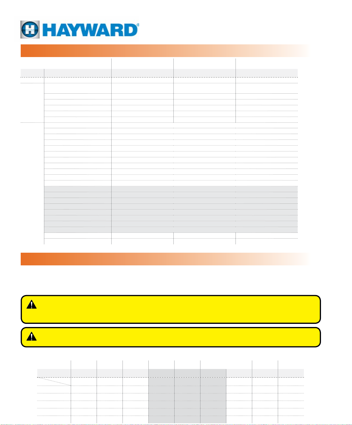
ACTUATOR SPECIFICATIONS ECP3 ECP5 ECP8
Supply Torque Output (lbf-in / Nm) 309 / 35 486 / 55 752 / 85
Maximum torque break (lbf-in / Nm) 336.3 / 38 531 / 60 796.6 / 90
24~240V
VDC/VAC
50/60Hz
ALL
Current Draw (Max Load)
24VDC / 24VAC / 120VAC / 230VAC
Speed (90°) 60Hz/50Hz, seconds 10 14 30
Motor - 2P Brush, 24vdc 90W 90W 90W
Duty Cycle (on/off and mod) 75% 75% 75%
Motor Starts, per hour, Max 1200 1200 1200
Motor Protection, Temp / Class 130°C / Class B 130°C / Class B 130°C / Class B
Electrical Entry (2) EN175301-803 DIN Connectors
Control On/Off or Proportional
Proportional Control Interface 4-20mA, 2-10vdc, 0-10vdc - Factory Installed (PC Option)
Battery Backup Option Available Factory Installed (BB Option)
Ambient Operating Range -20ºC +70ºC / -4ºF +158ºF
Humidity Range 0-95% RH
Altitude Limit 9850 ft / 3000 m
Working angle 0°-90º, 0°-180º
Limit switch 4 SPDT Microswitch ( 2 Travel Stop and 2 Aux) Rated 3A@250vac Max
Automatic heater 3.5 W
Protection IEC 60529 rating IP67
Housing: Polyamide (lid & body)
Main external shaft: Stainless Steel
External screws: Stainless Steel
Gears: Steel and Polyamide
Visual position indicator: Polyamide
Dome: Polycarbonate
Adjustable internal cams: Polyamide
Insulation: Class B
ISO 5211 Plate F03/F04/F05 F05/F07 F05/F07
Drive Socket 14mm DSQ 14mm DSQ 14mm DSQ
1.20 / 1.60 / 0.30 / 0.20 1.25 / 1.73 / 0.37 / 0.2 0.90 / 1.17 / 0.27 / 0.16
WIRE SIZING CHART
Wire sizing data is provided in the table below to assist in the selection of the proper wire size for Hayward ECP Series
actuators using various wire sizes over distance. Make sure to reference the correct voltage and do not exceed the
indicated length of the wire run for each model.
WARNING – Hayward assumes no responsibility for improper wire selection or improper
wiring. Wire selection and installation is the ultimate responsibility of the
user, and must follow local code requirements.
WARNING – To avoid dangerous or fatal electrical shock, turn OFF power to all
electrical equipment before working on electrical connections.
Maximum distance between Actuator and Power Supply (ft)
ACTUATOR
Voltage
AWG
20 67 1791 5150 62 1452 5150 92 1990 6438
18 107 2848 8187 99 2309 8187 146 3164 10234
16 170 4527 13016 157 3671 13016 232 5030 16270
14 270 7201 20702 250 5838 20702 369 8001 25878
12 429 11450 32917 397 9283 32917 587 12722 41147
ECP3 ECP3 ECP3 ECP5 ECP5 ECP5 ECP8 ECP8 ECP8
24 110 230 24 110 230 24 110 230
Amps
1.6 0.3 0.2 1.73 0.37 0.20 1.17 0.27 0.16
Page 5
MODELS: ECP3, ECP5 & ECP8
On/Off and Proportional Control
24~240V
ECP COMPONENT IDENTIFICATION
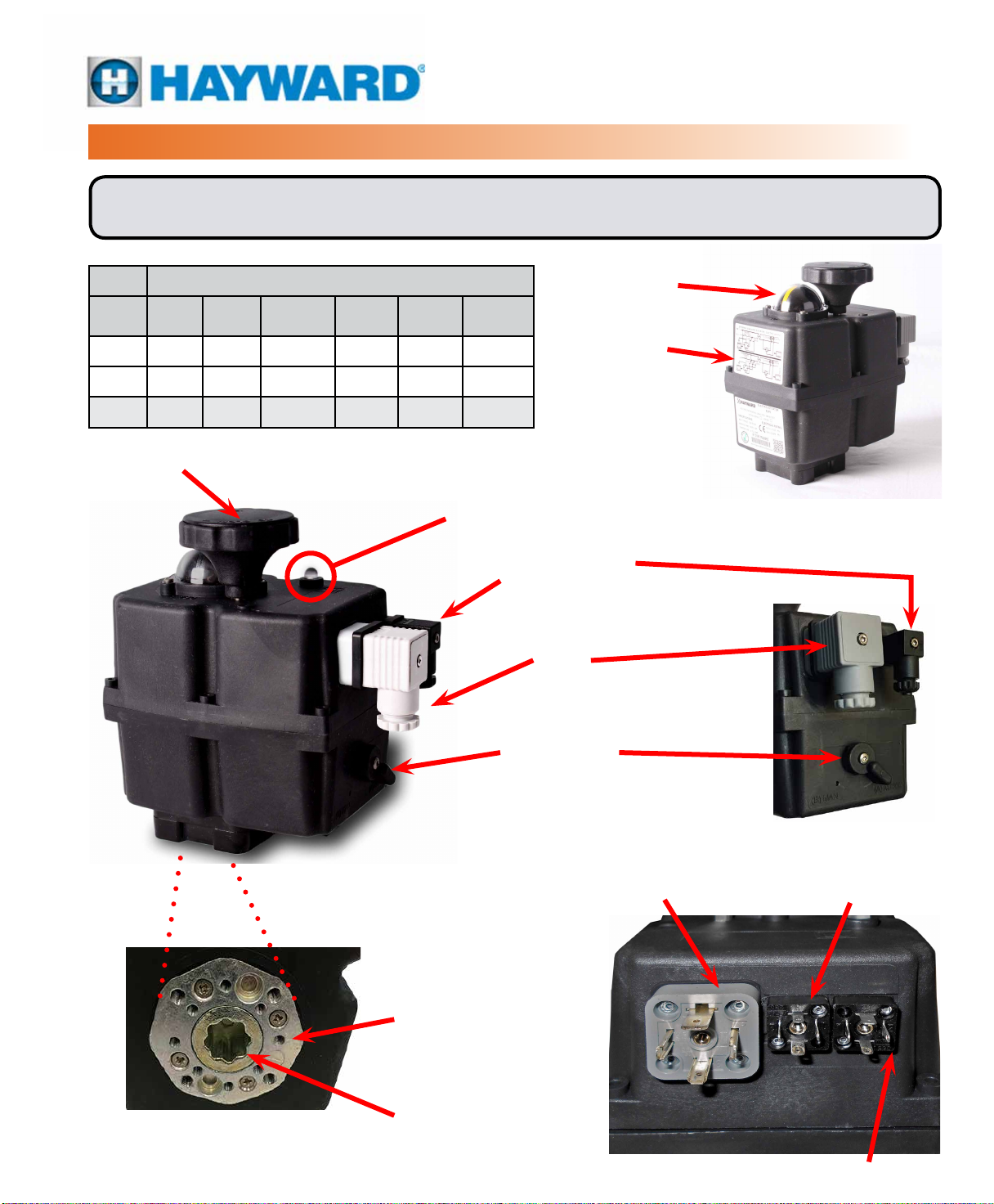
Notice: ECP Series Manual Override Handwheels rotate CW to close the output shaft out
the bottom of the actuator when viewed from above except the ECP8, see the table below.
Rotation
Model
ECP3 CW CW CW CCW CCW CCW
ECP5 CW CW CW CCW CCW CCW
ECP8 CCW CW CW CW CCW CCW
Hand
wheel
Output
Shaft
Indicator
Hand
wheel
Output
Shaft
Indicator
MANUAL OVERRIDE HANDWHEEL
Note - See table above for handwheel
rotation information by actuator model.
OPERATIONAL STATUS LED
POSITION INDICATOR
PRODUCT LABELS
VOLT FREE AUXILIARY
SWITCH PLUG
POWER SUPPLY
PLUG
DECLUTCH LEVER
(ECP3 Actuator Shown)
(On/Off Actuator Shown)
ISO 5211
MOUNTING FLANGE
14mm Double Square (DSQ)
Drive Socket
POWER SUPPLY
PLUG
(Proportional Model)
(On/Off Actuator Shown)
INPUT / OUTPUT SIGNAL PLUG
(4-20mA, 2-10V, 0-10V)
VOLT FREE AUXILIARY
SWITCH PLUG
Page 6
QUICK REFERENCE GUIDE
MODELS: ECP3, ECP5 & ECP8
On/Off and Proportional Control
24~240V
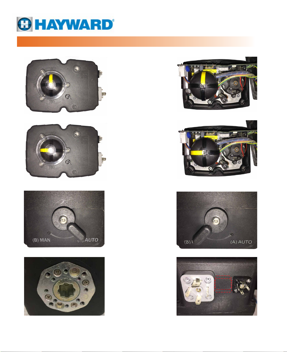
ECP Series shown at 0° rotation
(FULL CW Position) with
cover ON and with cover OFF.
ECP Series shown at 90° rotation
(FULL CCW Position) with
cover ON and with cover OFF.
ISO 5211 Mounting on the bottom surface
for ECP products. Hole patterns included are
F03, F04 & F05 with 14mm DSQ drive socket
for the ECP 3 and F05 & F07 with 14mm
DSQ drive socket for the ECP 5 and ECP 8.
ECP Series shown with Declutch
Lever in the (A) AUTO position (left)
and the (B) MAN position (right).
Note: always remove power
before using the (B) MAN mode.
All electrical connections are made to the
DIN Connectors. Large grey is for power
and control. Small black is for Auxiliary
Switch outputs. Proportional actuators
have a third DIN Connector (center).
Page 7
ACTUATOR HANDLING AND INSTALLATION
SHIPPING AND HANDLING
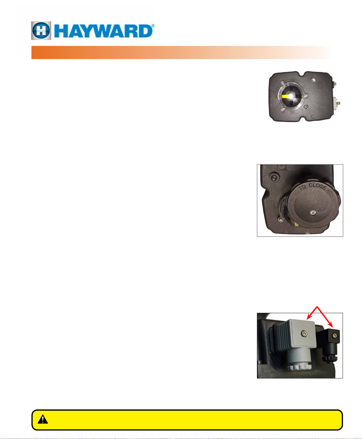
1. This actuator arrives in the FULLY OPEN (CCW) position. The yellow position
indicator (see photo) shows full CCW (90°) position.
2. Storage: This unit should not be stored outside unless it is powered up and
has proper electrical terminations. When not powered up, it should be stored
in a clean, dry environment at all times.
3. This actuator has been factory tested and calibrated to operate between 0°
and 90°. Most products will not require recalibration of these settings. If any
travel adjustment is necessary, please refer to the Adjusting CW/CCW End
of Travel section for instructions.
4. Notice: The ECP series actuators have NO mechanical stops to limit rotation.
Do not operate with a rotation greater than 90° unless it has been properly
calibrated to do so.
5. Notice: Protect the actuator from moisture by supplying power to the unit to
keep the internal heater warm at the time of installation.
• For On/Off actuators, in order to keep the 3.5W internal condensate
heater powered up, the actuator needs to receive a continuous OPEN or
CLOSED command at all times.
• For modulating actuators, power on terminals 1 & 2 at all times provides
the required power for the heater.
The actuator is shipped (assembled to
a valve) from the factory in its fully CCW
(90° OPEN) position. The YELLOW stripe
indicates the position of the actuator.
INSTALLATION NOTES
• There are no mechanical stops on the ECP series. Use caution when
operating the manual override. Rotating the drive beyond its intended
rotational angle will cause erratic operation under power. Keep the yellow
stripe between the established rotation angles – in most cases 0° to 90°.
• These actuators are designed to be used between a horizontal and
upright position. Do NOT mount the assembly with the actuator top
below a horizontal position (i.e. upside down).
• Notice: Use the DIN connectors supplied with the actuator for eld wiring.
• Use supplied DIN connectors and gaskets during installation to protect
the IP67 integrity of the housing.
• The internal heater is to be used in ALL applications.
• Do NOT install the actuator outdoors or in humid environments unless it
is powered up and the heater is functioning.
• Use proper wire size and cable sheath diameter to prevent actuator
failure (see Wire Sizing Chart on page 4 for proper wire sizing).
• Notice: Parallel wiring of multiple on/off actuators is permissible on the
ECP Series.
• ECP Series On/Off actuators utilize two DIN EN 175301-803 connectors
for power and control to simplify eld wiring and testing. ECP Series
Proportional actuators utilize three DIN EN 175301-803 connectors.
The manual override handwheel (ECP3/5
shown), allows a user to position the
valve or damper with or without power.
The arrow molded in the handwheel
cover shows the direction you must turn
the handwheel to close the actuator
and attached device (ECP8 is reversed).
DIN Connectors
Removable DIN EN 175301-803
connectors facilitate ease of eld
wiring and testing.
WARNING – To avoid dangerous or fatal electrical shock, turn OFF power to all
electrical equipment before working on electrical connections.
Page 8
PRODUCT MOUNTING AND SETUP
Notice: All ECP Series actuators rotate CW to close the output shaft
out the bottom of the actuator when viewed from above. On all ECP
models, the cam shaft and the indicator rotate CW to close as well.
1. Fully CLOSE the valve or damper to which the actuator is to be mounted.
2. Assemble necessary linkage hardware and attach the actuator to the valve
or damper.
3. Center the actuator on the valve or damper drive shaft and tighten all hardware.
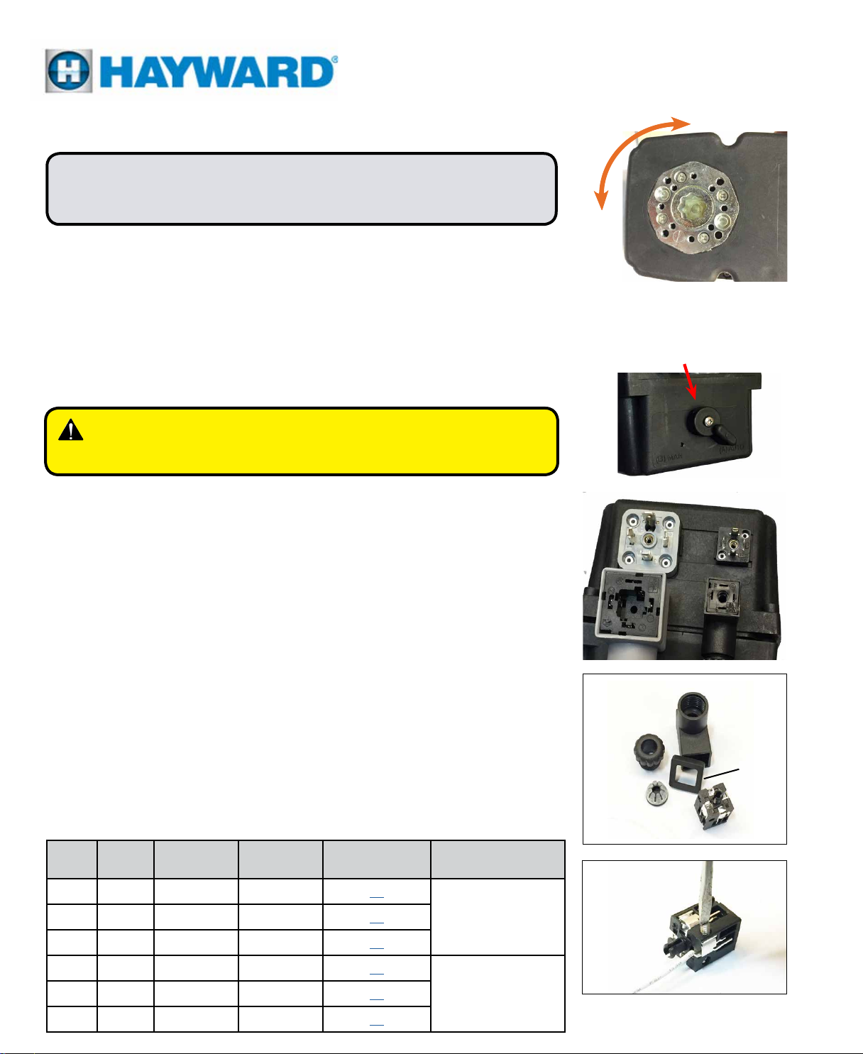
4. Before applying power to the unit, disengage the declutch lever by rotating
it from (A) AUTO to (B) MAN and rotate the manual override handwheel from
the fully CW to the fully CCW position to check for unobstructed manual
operation of the valve or damper.
WARNING – Do not try to rotate the hand wheel without
disengaging the declutch lever. This will damage
the geartrain.
Make the electrical connections per wiring diagrams found in the Wiring Diagrams
Sections of this document:
• To remove a connector from the actuator cover, unscrew the 2mm SHCS
(socket head cap screw). Remove the connector and set the seal aside.
• Gently pull the inner portion of the connector out of the housing. Slide
the wiring cable into the housing past the cable seal.
• Attach wires to the inner portion of the connector according to the
appropriate wiring diagram.
• After wiring, reinsert the inner portion of the connector into the housing.
• Place the seal boot, at side against actuator, and reattach the connector
to the actuator cover using the 2mm SHCS.
• Tighten the cable seal/lock. Use care as overtightening the cable lock
can permanently damage the DIN Connector.
5. Connect POWER and CONTROL to the correct terminals.
6. The smaller DIN connector on each On/Off actuator is for the (adjustable)
aux switches. These are dry type (volt free) Form A contacts rated 250VAC
@ 3A Max.
7. Proceed to Commissioning for your On/Off or Proportional Actuator.
CCW
CCW
CW
CW
Note that the rotation seen from
below is a mirror of the direction
viewed from above.
Declutch Lever
Housing
Cable Lock
Seal Boot
Cable Seal
Inner Portion
Model On/Off Proportional Option
ECP3 X 10
ECP5 X 10
ECP8 X 10
ECP3 X PC 13 BB option for
ECP5 X PC
ECP8 X PC 13
Wiring Diagram
See Page:
13
Note
BB option for On/Off
Actuator uses On/Off
Wiring Diagram
Proportional Actuator
uses Proportional
Wiring Diagram
Attach wires to the inner portion of the
connector according to the appropriate
wiring diagram
Page 9
OPERATIONAL STATUS LED
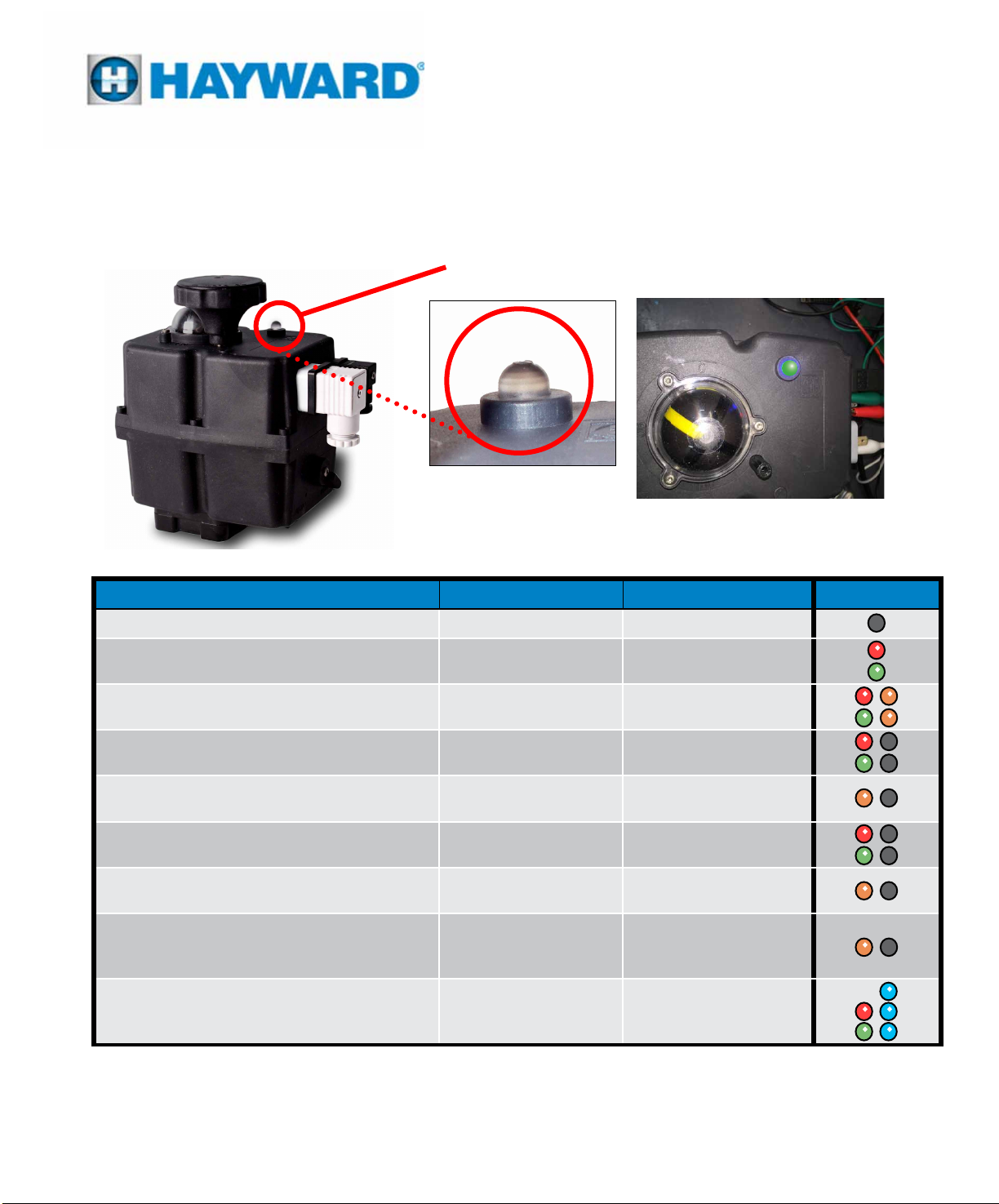
The LED Light provides visual communication between the actuator and the user.
The active operational status is shown by different LED colors described in the table
below.
MODELS: ECP3, ECP5 & ECP8
OPERATIONAL STATUS INDICATOR
Actuator Operational Status Actuator Action LED Behavior LED Colors
Actuator Without NO Power Supplied
Actuator With Power Supplied
(Normal On/Off Operation)
Actuator Moving:
(Flashing LED)
Actuator With Torque Limiter Function On
(Flashing LED)
Actuator In Manual Mode
Battery Backup: Actuator Without Power
(Maximum 3 Minutes)
Battery Backup:
Danger, the battery needs recharging.
Battery Backup:
Power Failure with quick recovery(*)
(less than 3 minutes)
Actuator with Proportional Controller
(Normal Proportional Operation)
Position: CW (Close)
Position: CCW (Open)
Driving CW (Closed)
Driving CCW (Open)
Driving CW (Closed)
Driving CCW (Open)
BSR in NC Position
BSR in NO Position
BSR not functioning
BSR not functioning
Stop
Driving CW (Closed)
Driving CCW (Open)
LED Off
Red LED
Green LED
Red / Orange
Green / Orange
Red / Off
Green / Off
Orange / Off
(Symmetric Sequence)
Red / Off
Green / Off
Orange / Off
(Asymmetric Sequence)
Orange / Off
(Asymmetric Sequence)
Repeated 5 times.
Blue
Red / Blue
Green / Blue
(*) When an actuator with a BSR 2015 experiences a power supply failure but recovers in less than 3 minutes,
it will recover and the LED will signal the fault.
To reset this fault, the actuator should be disconnected from the power supply, and wait until the LED is off
(approximately 3 minutes).
After the LED resets the actuator is again operational.
Page 10
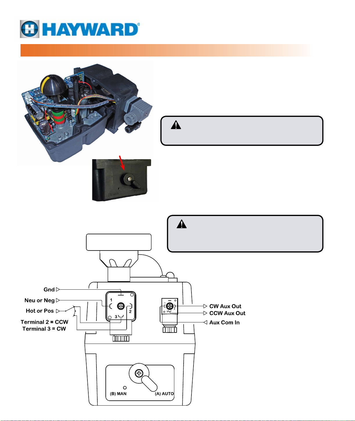
ON/OFF CONTROL
MODELS: ECP3, ECP5 & ECP8
On/Off Control
24~240V
The ECP Series actuators in their base congurations are
designed to operate in On/Off Control applications. These
models will also allow a “Jog” Control scheme to stop at any
point between the full CW and full CCW positions.
The ECP Series actuators have 2 operating modes,
automatic and manual. Use the Declutch Lever on the lower
half of the actuator housing to select the required mode.
CAUTION! - Do not remove the declutch lever securing
screw. This will cause irreparable damage to the actuator’s
gearbox and will invalidate the warranty.
WIRING DIAGRAM
Declutch Lever
When (B) MAN function is desired:
1. Remove power to the actuator.
• The Operational Status LED will not be lit.
2. Rotate the Declutch Lever to (B) MAN.
• The output shaft drive train disengages from the motor,
allowing it to move.
3. The manual override hand wheel can now be used to
reach the desired position.
CAUTION! - ECP actuators have no mechanical
stops. When in Manual Operation mode always
keep the actuator within the 0˚ to 90˚ quadrant
to protect the valve or damper attached.
Return to (A) AUTO after being in (B) MAN position:
1. Rotate the Declutch Lever to (A) AUTO.
2. Reapply power to the actuator.
3. The actuator will respond to the On/Off
control signals.
VIEW LOOKING AT ACTUATOR
Page 11

ON/OFF CONTROL
CALIBRATION AND COMMISSIONING
This actuator has been factory calibrated to operate over the full range of a quarter turn valve with end-of-travel
stops set and tested. There should be no reason to make adjustments to these settings. If this actuator was
provided installed to a Hayward valve the stops have been set for that valve. However, if the actuator was provided
as a separate component, you may nd it is necessary to set the end-of-travel stops. In that case refer to the
sections “Adjusting CW(CCW) End of Travel” before proceeding.
Once it has been determined that end-of-travel positioning is correct, and the auxiliary switch cams are also
properly set, the installed assembly can be commissioned as follows:
WARNING – Serious Damage to connected valves or devices will result if the motor is
allowed to drive past the mechanical limits of the valve or driven device!
Remove power from this device BEFORE making any travel adjustments.
Calibration Procedure - On/Off Control
1. On battery back-up equipped units, disconnect the battery before proceeding.
2. Disconnect power and place the declutch lever in “Man” position.
3. Manually rotate the hand wheel to exercise the valve through its full travel fully CW and back to full CCW positions.
• This checks for obstructions in the operation of the valve.
• If no hindrances to valve travel are found, return the declutch lever to “Auto” position.
4. Reconnect Battery pack if so equipped.
5. Apply power and command the actuator to drive to the full CW position.
• The actuator should drive CW until the yellow indicator line reaches the 0° mark.
• The actuator should stop even with the control signal remaining active.
6. Apply power and command the actuator to drive to the full CCW position.
• The actuator should drive CCW until the yellow indicator line reaches the 90° mark (or the 180° mark on TW
Series Ball Valves).
• The actuator should stop even with the control signal remaining active.
7. On battery backup equipped units, the unit needs to charge for 24 hours after applying power before the battery
acquires a full charge.
• The battery system may be tested here by driving the actuator to a mid-travel point, and then disconnecting power.
• The actuator should (if it has enough charge) drive the valve to the chosen fail-safe direction (see page 15
of this document).
• On battery back up equipped units, the battery system is charging when the actuator is receiving either a full-
time drive CW or CCW command.
• When there is no drive signal present, the battery system is NOT charging. Charge the battery system for at
least 24 hours before reaching full capacity.
8. Commissioning is complete. Unit can be put into service.
Page 12
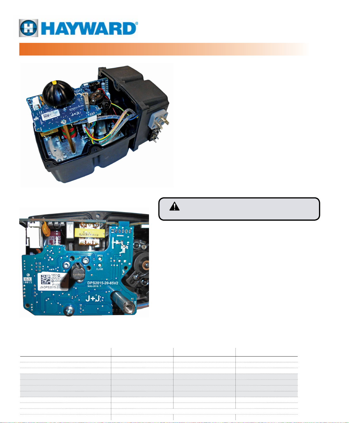
PROPORTIONAL CONTROLLER
MODELS: ECP3, ECP5 & ECP8
Proportional Control
24~240V
Proportional Control (PC) is an interface for the ECP
Series electric actuators that effectively turns the
actuator into a servo controlled valve positioner.
The PC is a microprocessor (CPU) module which
digitally manages the analog input and output
and compares them with the position of the
actuator to establish a uniform relationship.
The analog inputs are sent to the CPU where
they are processed for continuous comparison
with the position of the actuator. This allows
for very high sensitivity along with very high
repeatability of the position (see Controller
Specifications).
Proportional Control ECP Series actuators can be
congured to receive and send 4-20mA, 2-10V, or
0-10V signals.
CAUTION! - If so equipped, the BB Option (see page 16)
must be installed prior to the PC Option.
When (B) MAN function is desired:
1. Remove power to the actuator.
• The Operational Status LED will not be lit.
2. Rotate the Declutch Lever to (B) MAN.
• The output shaft drive train disengages from the motor,
allowing it to move.
3. The manual override hand wheel can now be used to
reach the desired position.
Return to (A) AUTO after being in (B) MAN position:
1. Rotate the Declutch Lever to (A) AUTO.
2. Reapply power to the actuator.
3. The actuator will respond to the Proportional control signals.
CONTROLLER SPECIFICATIONS ECP3 ECP5 ECP8
Accuracy 3 % F.S. 3 % F.S. 3 % F.S.
Linearity 2 % F.S. 2 % F.S. 2 % F.S.
Hysteresis 3 % F.S. 3 % F.S. 3 % F.S.
Steps at 4-20mA Min.142 steps 90º Min.142 steps 90º Min.142 steps 90º
Steps at 2-10V Min.88 steps 90º Min.88 steps 90º Min.88 steps 90º
Steps at 0-10V Min.88 steps 90º Min.88 steps 90º Min.88 steps 90º
Steps at 1-10V Min.85 steps 90º Min.85 steps 90º Min.85 steps 90º
4-20mA Input signal impedance 100 Ohm 100 Ohm 100 Ohm
2-10V or 0-10V Input signal impedance 25K Ohm 25K Ohm 25K Ohm
Class B+C to E DIN EN 15714 Inching + Modulation
Weight (lb / Kg) 1.32 / 0.600 1.32 / 0.600 1.32 / 0.600
Page 13
2
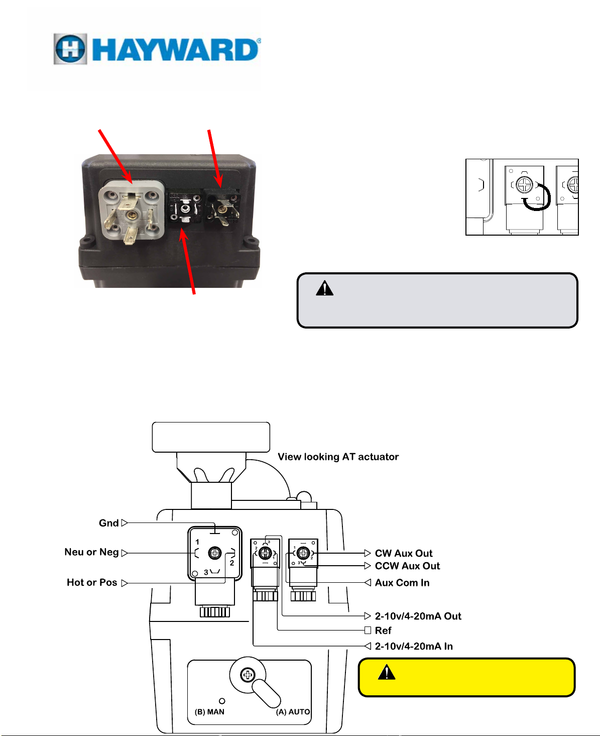
PC OPTION - EXTERNAL SELF-ADJUSTMENT
MODELS: ECP3, ECP5 & ECP8
Proportional Control
24~240V
POWER SUPPLY
PLUG
VOLT FREE AUXILIARY
SWITCH PLUG
INPUT / OUTPUT SIGNAL PLUG
(4-20mA, 2-10V, 0-10V)
Note that the center black DIN
Connector is mounted upside
down from the right DIN Connector.
WIRING DIAGRAM
Proportional Controller Self Adjustment
Test the basic functionality of proportional card before attaching
the drive signal.
Disconnect power.
1. Remove the Input / Output
Signal Plug (center plug) and
connect a jumper between PIN
2
3
2
1
1
3
1 (on the right side) and PIN
Earth (on the bottom).
2. On the Power Supply Plug,
connect power as shown in the
wiring diagram below.
CAUTION! - Do not swap the center plug and right plug.
Doing so will damage the PC Module. Note
that these plugs are keyed.
3. Allow at least 3 seconds and proceed to the next step.
4. On the Input / Output Signal Plug, disconnect the jumper
between PIN 1 (right side) and PIN Earth (bottom pin).
5. The actuator will make a complete 0˚-90˚-0˚ maneuver and
then remain in the CW (CLOSED) position.
6. The actuator has completed its self test and is ready to
connect the (4-20mA, 2-10V, or 0-10V) signal to the Input /
Output Signal Plug.
3
1
2
-
+
WARNING – Instrumentation Signal
Only - No Voltage
Page 14
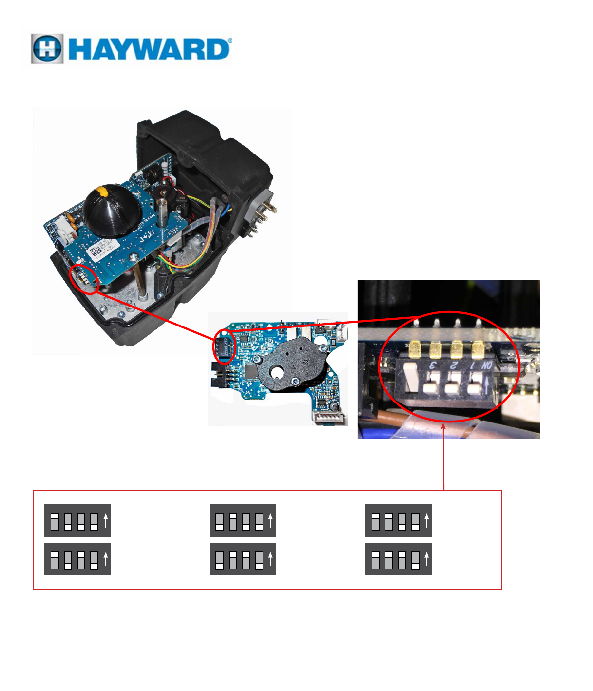
PC OPTION - CONTROLLER SETUP
MODELS: ECP3, ECP5 & ECP8
Proportional Control
24~240V
Choose the conguration you need by moving the
DIP switches located on the edge of the PC Option
Positioner PCB.
(PCB is shown bottom side
up for component clarity)
Conguration Options
ON 1 2 3 4ON 1 2 3 4
4 – 20mA
Direct Acting
ON 1 2 3 4ON 1 2 3 4
4 – 20mA
Reverse Acting
Congure the actuator control by using the DIP Switches shown in pictures above.
• Put DIP 1 in ON position, connect the grey connector to the power supply, put DIP 1 back to the prior
position. Wait until the actuator makes a complete 0˚-90˚-0˚maneuver.
• Choose the conguration you need and set the DIPs as shown.
• Disconnect the grey connector from the power supply.
2 – 10 VDC
Direct Acting
2 – 10 VDC
Reverse Acting
ON 1 2 3 4
0 – 10 VDC
Direct Acting
ON 1 2 3 4
0 – 10 VDC
Reverse Acting
Page 15

PROPORTIONAL CONTROL
CALIBRATION AND COMMISSIONING
This actuator has been factory calibrated to operate over the full range of a quarter turn valve with end-of-travel
stops set and tested. There should be no reason to make adjustments to these settings. If this actuator was
provided installed to a Hayward valve the stops have been set for that valve. However, if the actuator was provided
as a separate component, you may nd it is necessary to set the end-of-travel stops. In that case refer to the
sections “Adjusting CW(CCW) End of Travel” before proceeding.
Once it has been determined that end-of-travel positioning is correct, and the auxiliary switch cams are also
properly set, the installed assembly can be commissioned as follows:
WARNING – Serious Damage to connected valves or devices will result if the motor is
allowed to drive past the mechanical limits of the valve or driven device!
Remove power from this device BEFORE making any travel adjustments.
Calibration Procedure - Proportional Control
1. On battery back-up equipped units, disconnect the battery before proceeding.
2. Disconnect power and place the declutch lever in “Man” position.
3. Manually rotate the hand wheel to exercise the valve through its full travel fully CW and back to full CCW positions.
• This checks for obstructions in the operation of the valve.
• If no hindrances to valve travel are found, return the declutch lever to “Auto” position.
4. Reconnect Battery pack if so equipped.
5. Apply power and command the actuator to drive to the full CW position (refer to page 14 of this document for
signal detail).
• The actuator should drive CW until the yellow indicator line reaches the 0° mark and the actuator should stop.
6. Read the feedback signal being generated by the proportional control module.
• The feedback signal follows the position of the actuator and is a function of DIP settings (see page 14 of this
document).
7. Command the actuator to drive to the full CCW position.
• The actuator should drive CCW until the yellow indicator line reaches the 90° mark (or the 180° mark on TW
Series Ball Valves) and the actuator should stop.
8. Read the feedback signal being generated by the proportional control module.
9. On battery backup equipped units, the unit needs to charge for 24 hours after applying power before the battery
acquires a full charge.
• The battery system may be tested here by driving the actuator to a mid-travel point, and then disconnecting power.
• The actuator should (if it has enough charge) drive the valve to the chosen fail-safe direction (see page 15
of this document).
• On battery back up equipped units, the battery system is charging when power is applied to the actuator, and
does NOT require an active command signal to charge the battery system.
• Charge the battery system for at least 24 hours before reaching full capacity.
10. Commissioning is complete. Unit can be put into service.
Page 16
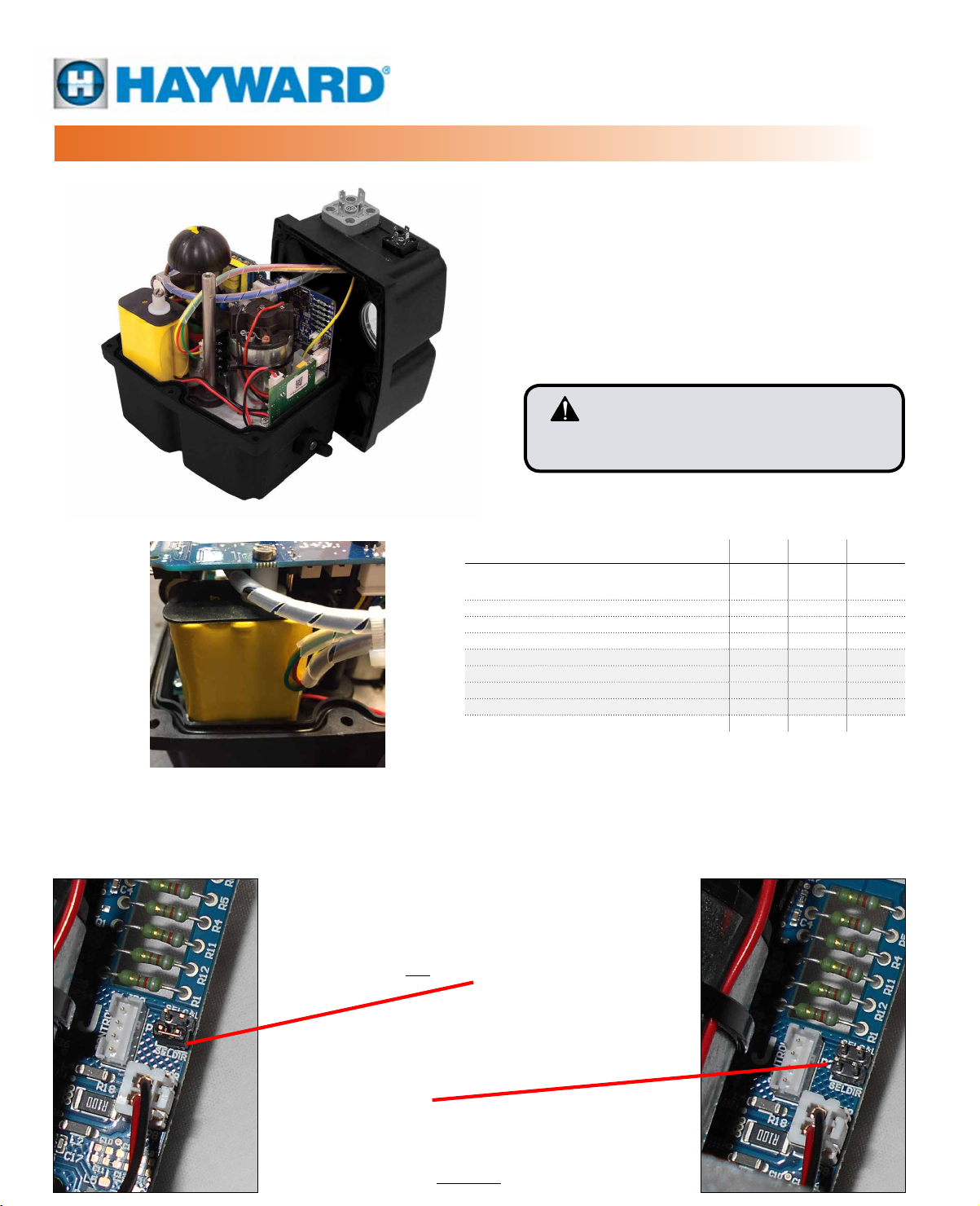
BB BATTERY BACKUP
MODELS: ECP3, ECP5 & ECP8
On/Off and Proportional Control
Battery Backup for 24~240V
The BB Battery Backup option, when properly
installed in the ECP Series electric actuators, uses
internal battery power to drive the actuator and linked
valve or damper to a Fail CW or Fail CCW position in
case of a power supply failure.
Inside the housing there is a BB printed circuit board
and a battery pack, which is kept continuously
charged when the actuator is receiving a continuous
drive CW or drive CCW command.
CAUTION! - If so equipped with the PC
Option (see page 12), the BB Option must
be installed prior to the PC Option.
(On/Off Actuator Shown)
(Battery installed beneath
Proportional Model PCB)
SETUP FOR FAIL CW/CCW
Fail CW Set-Up
If, in case of a power supply failure, we want the
actuator go to the CW (CLOSED) position:
Place jumper 1 ON the SELDIR position.
CONTROLLER SPECIFICATIONS ECP3 ECP5 ECP8
Number of operations before recharge (from 100%
battery charge )
Recharge time/working operation (Minutes) 21 48 58
Battery consumption/working operation (W) 3.0 6.8 8.3
Full charge time 100% (Hours) 28 28 28
Nominal capacity +/- 5% (mAh) 1000 1000 1000
NO or NC Selection Jumper Jumper Jumper
Current/one working operation with battery (mA) 14 31.6 38.6
Battery charge (mA/h) 40 40 40
Weight (lb / Kg) 0.6 / 0.27 0.6 / 0.27 0.6 / 0.27
Note: Unit needs to charge for 24 hours after applying power
before the battery acquires a full charge. This must be
done before placing the Battery Backup Option in service.
5 5 5
Fail CCW Set-Up
If, in case of a power supply failure, we want the
actuator go to the CCW (OPEN) position:
Be sure jumper 1 is NOT ON the SELDIR position.
Page 17
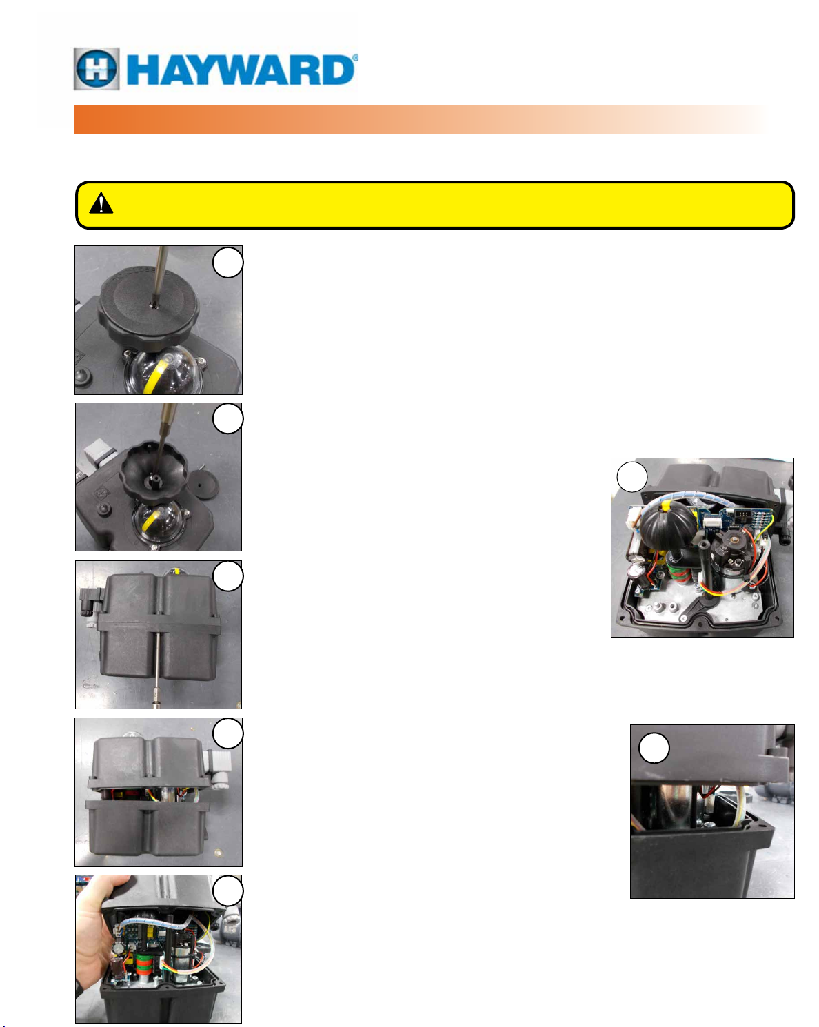
DISASSEMBLY / ASSEMBLY
This actuator has been factory calibrated and tested and most installations will likely not require entry into the
body of the actuator. See page 18 for a more in depth explanation before using the instructions on this page.
WARNING – To avoid dangerous or fatal electrical shock, turn OFF power to all
electrical equipment before working on electrical connections.
Disassembly of actuator
2
3
4
5
5B
Use the photos at left, the numbers indicate the disassembly step to follow.
1. Disconnect power.
2. Remove the phillips screw holding the cover onto the manual override handwheel.
Remove the cover and set both parts to the side.
3. Use a T15 Torx drive to remove the socket head cap screw (SHCS) holding the
manual override handwheel. Carefully pry straight up to remove the handwheel
and set both parts to the side.
4. Use a T15 Torx drive to remove the six socket head cap screws (SHCS) holding the
cover to the body of the actuator.
5. Carefully pull the cover straight up approximately 2
inches to separate it from the body.
A. Use caution because the wiring inside the
actuator is attached to both the cover and
the body.
B. Carefully pull the cover the rest of the way up
and set the cover behind the actuator, minding
the cables so they do not stretch or pull.
6. You now have access to the interior of the actuator.
Assembly of actuator
Use the photos at left in reverse order for reference.
7. Disconnect power.
8. Carefully pull the cover from its resting place and reposition it over the actuator body.
A. Align the manual override handwheel shaft with the hole in the cover.
B. Mind the cables so they do not stretch, pull, get
hung up on the actuator components, or get
pinched in the cover as it comes down into place.
9. Use a T15 Torx drive to replace the six socket head
cap screws (SHCS) which hold the cover to the body
of the actuator.
10. Carefully align the handwheel to the manual override
handwheel shaft. DO NOT force it into place. Gently
push it down into position, it should be a smooth t.
Use a T15 Torx drive to reattach the socket head
cap screw (SHCS) which secures the manual
override handwheel.
11. Replace the phillips screw into the cover of the manual override handwheel and
secure it.
12. You now have completed reassembly.
6
8B
Page 18
COM
NONC
CW Limit Switch
Shown in CCW Position
Will drive 90°CW
COM
NONC
CCW Limit Switch
Shown in CCW Position
CCW Limit Switch
Shown in Full CW Position
COM
NONC
Will drive 90°CCW
COM
NONC
CCW Limit Switch
Shown in CCW Position
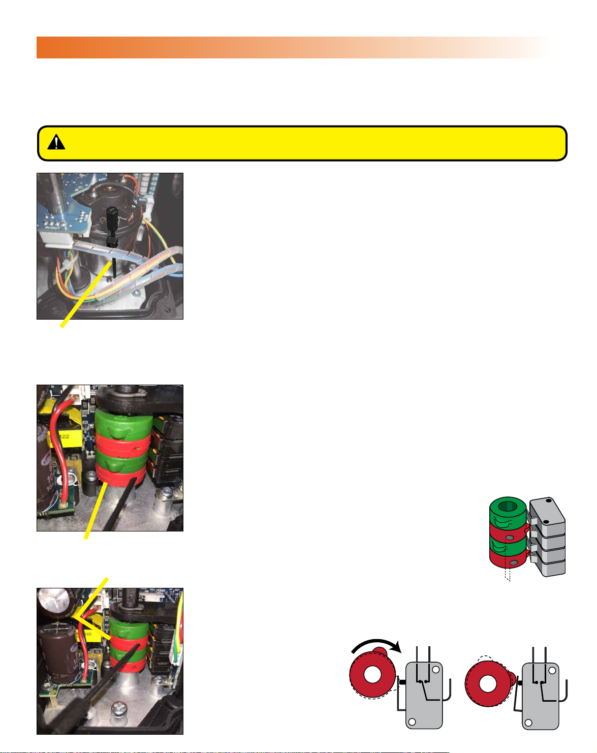
ADJUSTING CW END OF TRAVEL
This actuator has been factory calibrated and tested to stop at 0 degrees for CW position and to stop at 90 degrees for
CCW position. Most installations onto valves or dampers will likely not require recalibration of these settings. Please
mount the valve or damper and proceed on these pages only if adjustments are required. Note that for most actuators
these positions are independent - for instance the CW position is set correctly while the CCW needs adjustment.
WARNING – To avoid dangerous or fatal electrical shock, turn OFF power to all
electrical equipment before working on electrical connections.
Cam Adjustment Tool and Adjusting Cams
1. Disconnect power.
2. Cam adjustment tool is stored next to the DC drive motor and is held in
place by a wire tie surrounding the motor. The tool must be used to make
adjustments to the cam positions.
• This key is nonconducting.
3. All adjustments with the hex key affect a worm gear in the cam. This means
ne adjustments may be made to actuator positioning by rotating the hex
key for instance 1-3 degrees CW and then 1-3 degrees CCW.
4. Take care not to drive the actuator out of its original 0°–90° quadrant.
Adjust CW Cam (Bottom)
Plastic Hex Key
Cam 1 - CW Cam
Cam 3 - CW Auxiliary Cam
5. Cam 1 is the bottom cam (red) and is the end-of-travel adjustment for the
actuator CW position.
• With power OFF and the actuator at its required CW position, insert the
adjustment tool into the bottom cam.
• Rotate the tool CCW to stop the actuator SOONER (less CW or closed).
• Rotate the adjustment tool CW to stop the actuator LATER (more CW
or closed).
6. Apply power and test the new setting.
• If the actuator stops at the required position, proceed to the next step.
• If it does NOT stop in the correct position, repeat step 5.
Adjust CW Auxiliary Cam (Cam 3)
7. Adjust Cam 3 (the Auxiliary switch cam) AFTER
adjusting Cam 1 (the end of travel cam).
• Ensure that Cam 3 LEADS the end-of-travel cam
by a few degrees, thereby changing state before
the end of travel cam stops the actuator.
• The adjustment tool hole for Cam 3 should be a few
degrees to the LEFT of Cam 1 adjustment tool hole,
see illustration.
8. Test the Cam 3
setting and readjust if
necessary.
9. CW Cam settings are
Will drive 90°CW
CAM BEHAVIOR
now complete.
CW Limit Switch
Shown in CCW Position
COM
NONC
CW Limit Switch
Shown in Full CW Position
NONC
COM
Page 19
COM
NONC
CCW Limit Switch
Shown in CCW Position
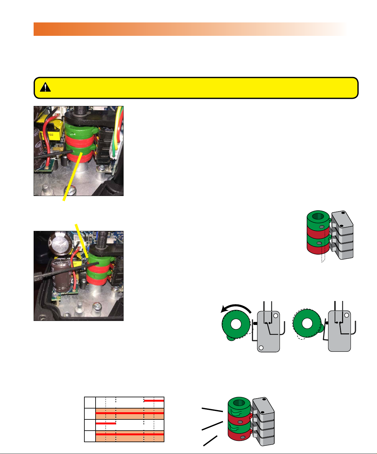
ADJUSTING CCW END OF TRAVEL
This actuator has been factory calibrated and tested to stop at 0 degrees for CW position and to stop at 90 degrees for
CCW position. Most installations onto valves or dampers will likely not require recalibration of these settings. Please
mount the valve or damper and proceed on these pages only if adjustments are required. Note that for most actuators
these positions are independent - for instance the CW position is set correctly while the CCW needs adjustment.
WARNING – To avoid dangerous or fatal electrical shock, turn OFF power to all
electrical equipment before working on electrical connections.
Adjust CCW Cam (Cam 2)
1. Cam 2 is the second cam (green) and is the end-of-travel adjustment for the
actuator CCW position.
• With power OFF and the actuator at its required CCW position, insert
the adjustment tool into the bottom cam.
• Rotate the tool CW to stop the actuator SOONER (less CCW or open).
• Rotate the adjustment tool CCW to stop the actuator LATER (more
CCW or open).
2. Apply power and test the new setting.
• If the actuator stops at the required position, proceed to the next step.
• If it does NOT stop in the correct position, repeat step 1.
Cam 2 - CCW Cam
Cam 4 - CCW Auxiliary Cam
Adjust CCW Auxiliary Cam (Cam 4)
3. Adjust Cam 3 (the Auxiliary switch cam) AFTER
adjusting Cam 2 (the end of travel cam).
• Ensure that Cam 4 LEADS the end-of-travel cam
by a few degrees, thereby changing state before
the end of travel cam stops the actuator.
• The adjustment tool hole for Cam 4 should be a
few degrees to the RIGHT of Cam 2 adjustment
tool hole, see illustration.
4. Test the CW aux
switch cam setting
and readjust if
necessary.
Will drive 90°CCW
CAM BEHAVIOR
5. CW Cam setting
are now complete.
NONC
NONC
AUXILIARY SWITCH CAM MAPPING
CW CCW
°
°
-5°0
D
C
B
A
5
Fully CCW (OPEN)
Common
Fully CW (CLOSED)
Common
Common Switch Terminal
85
COM
CCW Limit Switch
Shown in Full CW Position
90
°
°
95
}
}
SW4 CW AUX
(Adjustable)
SW3 CW AUX
(Adjustable)
SW1 and SW2
Used by Controller
}
CAM 4 / SW4
CAM 3 / SW3
CAM 2 / SW2
CAM 1 / SW1
°
CCW Limit Switch
Shown in CCW Position
COM
Page 20
MODELS: ECP3, ECP5 & ECP8
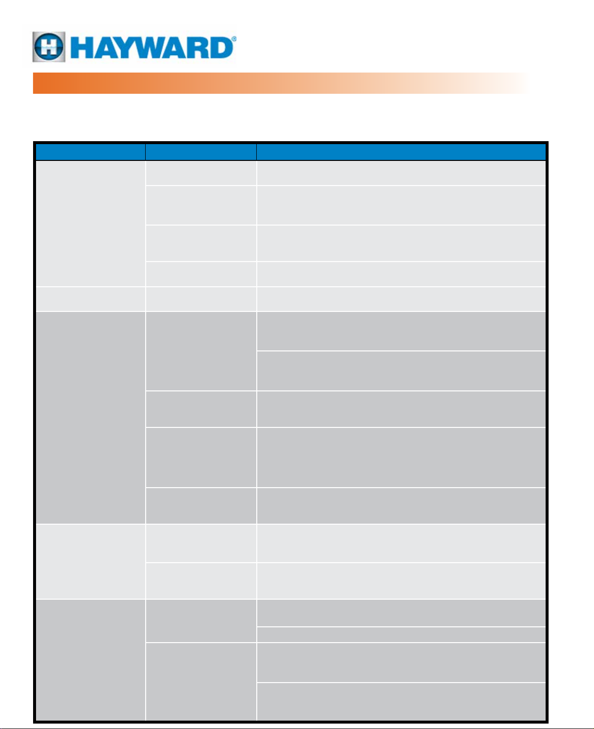
TROUBLESHOOTING
After completing all mounting and wiring procedures and main power is available, if the actuator does NOT respond as
expected, the following procedure(s) may help in identifying the problem. If using this troubleshooting guide does not
resolve your issue please contact Hayward Flow Control Technical Services at 888-429-4635.
Symptom Target Action
Power Source Measure incoming power AT the actuator Power Supply Plug.
Generate move commands by the eld device. Measure correct
Actuator does
not move when
commanded
to do so.
Supply and controls
are measured to
be correct, but
actuator still does
not move.
Control Problem
Declutch Lever
set to (B) MAN
Wire Sizing Check for correct wire size per Wire Sizing Chart.
Improper Wiring Check wiring per wiring diagram
Overtorque
DIP Switch Settings
(Proportional Only)
Insufcient power
supply and/or
incorrect wire size
during installation.
voltage changes between terminals 1 and 3 (CCW) and between
terminals 1 and 2 (CW) on the Power Supply Plug.
Reset Declutch Lever to Automatic.
Remove the actuator from the driven device. If the actuator now
moves, the torque required by the mechanical device exceeds
that of the actuator. Increase actuator size.
With the actuator removed from the mechanical equipment,
manually rotate the valve or damper through its intended range
of travel to check for mechanical problems or an obstruction.
Check to be sure the DIP Switch Settings match the incoming
control signal
Measure the voltage between terminals 1 & 2 WHILE
commanding the actuator to move. The measured voltage
cannot drop more than 10%.
Actuator does not
stop at correct
position at either
end of travel
Motor is extremely
hot to the touch.
Cams improperly
set.
Actuator is out of
quadrant
Travel cams not
positioned correctly
Control “noise” or
excessive duty cycle
Overtorque
Remove Power. Cams MUST be secure and set according to
the procedures in the Adjusting CW/CCW End of Travel section.
The manual override system has been employed to rotate the actuator
beyond its intended angle of rotation. Use the manual override to
rotate the actuator back into its correct quadrant of operation.
Reset end-of-travel cams as detailed in the Adjusting CW/CCW
End of Travel section.
Check for stray voltage uctuations on the incoming control
signals. The on/off actuators have a maximum 75% duty cycle.
Check the site as-built wiring diagrams to verify.
Remove the actuator from the driven device. If the actuator now
moves, the torque required by the mechanical device exceeds
that of the actuator. Increase actuator size.
With the actuator removed from the mechanical equipment,
manually rotate the valve or damper through its intended range
of travel to check for mechanical problems or an obstruction.
Page 21
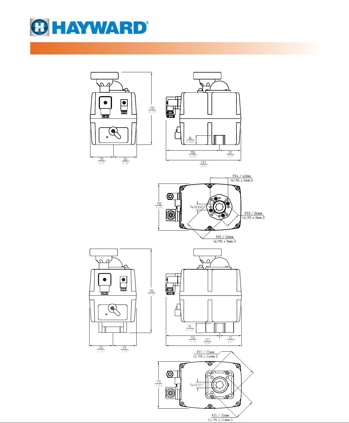
MECHANICAL DATA
MODEL: ECP3
MODELS: ECP3, ECP5
On/Off & Proportional Control
24~240V
MODEL: ECP5
Page 22
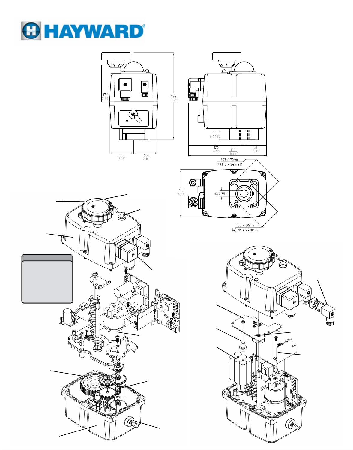
MODEL: ECP8
ECP3, ECP5 & ECP8
MODELS: ECP3, ECP5 & ECP8
On/Off & Proportional Control
24~240V
Easily distinguishable
yellow/black
Position Indicator
Anticorrosive
Polyamide
IP67 Protection
Cover
Inside the actuator
On/Off Control Card,
2 position,
3 position, optional
proportional control.
Internal Heater
Easily accessible
switch & cam stacks
IP67
Cover Seal
Manual Override Handwheel
Operational Status LED
Heavy Duty 24VDC
Steel and Polyamide
EN175301-803
DIN Connectors
Drive Motor
Gearing
Proportional
Control PCB
Mounting
Hardware
1000mAh
Battery Pack
Proportional Signal
EN175301-803
DIN Connector
Positioner Engagement
to Shaft
Battery Backup
Control PCB
Battery Backup
Wiring
(Not Showed)
Anticorrosive Polyamide
IP67 Protection Case
Back to TOC
Declutch Lever
(On/Off Actuator) (Proportional Model)
USE ONLY HAYWARD GENUINE REPLACEMENT PARTS
Page 23

MODELS: ECP3, ECP5 & ECP8
On/Off & Proportional Control
24~240V
MOTOR POWER CONSUMPTION
Wire sizing data is provided in the table below to assist in estimating the power consumption of the actuators in this
product line.
ECP3 CONSUMPTION Unload Max. Operational Torque 35Nm Max. Torque Break 38Nm
Voltage Amps Watts Amps Watts Amps Watts
24 VDC 0.40 10.20 1.20 27.60 1.20 28.20
48 VDC 0.20 9.30 0.50 24.40 0.50 25.40
110 VDC 0.10 7.30 0.20 18.20 0.20 18.60
24 VAC 0.60 14.10 1.50 36.40 1.60 38.10
48 VAC 0.40 17.20 0.90 41.90 0.90 43.80
110 VAC 0.10 15.20 0.30 37.30 0.30 38.00
240 VAC 0.10 22.70 0.20 45.90 0.20 45.90
ECP5 CONSUMPTION Unload Max. Operational Torque 35Nm Max. Torque Break 38Nm
Voltage Amps Watts Amps Watts Amps Watts
24 VDC 0.33 08.00 1.21 29.00 1.25 30.00
48 VDC 0.18 08.40 0.56 27.00 0.59 28.30
110 VDC 0.06 06.10 0.17 18.20 0.18 19.60
24 VAC 0.47 11.20 1.69 40.70 1.73 41.60
48 VAC 0.29 14.20 0.97 46.50 1.01 48.30
110 VAC 0.12 13.60 0.36 39.20 0.37 40.70
240 VAC 0.09 21.10 0.20 47.50 0.20 48.00
ECP8 CONSUMPTION Unload Max. Operational Torque 35Nm Max. Torque Break 38Nm
Voltage Amps Watts Amps Watts Amps Watts
24 VDC 0.33 7.90 0.88 21.20 0.90 21.20
48 VDC 0.17 8.10 0.44 21.20 0.48 23.20
110 VDC 0.05 5.80 0.13 14.80 0.15 16.50
24 VAC 0.45 10.80 1.16 27.70 1.17 28.00
48 VAC 0.28 13.30 0.28 33.10 0.71 34.10
110 VAC 0.11 12.30 0.26 29.00 0.27 29.50
240 VAC 0.08 18.50 0.16 38.00 0.16 38.00
 Loading...