

Hayward ECP3, ECP5, ECP8 Installation, Operation And Maintenance Instructions
INSTALLATION, OPERATION AND
MAINTENANCE INSTRUCTIONS
ECP3, ECP5, ECP8 Series Actuators
TO PREVENT POTENTIAL INJURY OR DAMAGE TO PROPERTY, READ THIS MANUAL CAREFULLY AND COMPLETELY.
IMPORTANT SAFETY INSTRUCTIONS
Basic safety precautions should always be followed, including the following: Failure to follow instructions
can cause severe injury and/or death.
This is the safety-alert symbol. When you see this symbol on your equipment or in this manual, look
for one of the following signal words and be alert to the potential for personal injury.
WARNING warns about hazards that could cause serious personal injury, death or major property
damage and if ignored presents a potential hazard.
CAUTION warns about hazards that will or can cause minor or moderate personal injury and/or
property damage and if ignored presents a potential hazard. It can also make consumers aware of
actions that are unpredictable and unsafe.
Notice:
A notice indicates special instructions that are important but not related to hazards.
WARNING - Read and follow all instructions in this IOM manual and on the equipment. Failure
to follow instructions can cause severe injury and/or death.
WARNING – Risk of Electric Shock. All electrical wiring MUST be in conformance with applicable
local codes, regulations, and the National Electric Code (NEC). Hazardous voltage can shock, burn,
and cause death or serious property damage. To reduce the risk of electric shock, do NOT use an
extension cord to connect unit to electric supply. Provide a properly located electrical receptacle.
Before working on any electrical equipment, turn off power supply to the equipment.
WARNING – To reduce the risk of electric shock replace damaged wiring immediately.
WARNING – Ground all electrical equipment before connecting to electrical power supply.
Failure to ground all electrical equipment can cause serious or fatal electrical shock hazard.
WARNING – Do NOT ground to a gas supply line.
WARNING – To avoid dangerous or fatal electrical shock, turn OFF power to all electrical
equipment before working on electrical connections.
WARNING – Failure to bond all electrical equipment to system structure will increase risk for
electrocution and could result in injury or death. To reduce the risk of electric shock, see installation
instructions and consult a professional electrician on how to bond all electrical equipment. Also,
contact a licensed electrician for information on local electrical codes for bonding requirements.
CAUTION – Potential pinch point. Equipment connected to or driven by this device may start
unexpectedly and may cause personal injury or entrapment in linkage systems.

TABLE OF CONTENTS
ECP Series
Important Safety Instructions .....................2
Table of Contents ...............................3
ECP Series Operational Concepts ..............3
Technical Information ...........................4
Wire Sizing Chart ...............................4
ECP Component Identication ....................5
Quick Reference Guide ..........................6
Actuator Handling And Installation .................7
Shipping and Handling .......................7
Installation Notes ............................7
Product Mounting And Setup ..................8
Operational Status LED .......................9
On/Off Control ................................10
Wiring Diagram ............................10
Calibration And Commissioning ..................11
On/Off Control .............................11
Proportional Controller .........................12
PC Option - External Self-Adjustment ..........13
Wiring Diagram ............................13
PC Option - Controller Setup .................14
Calibration And Commissioning ..................15
Proportional Control ........................15
BB Battery Backup ..............................16
Setup For Fail CW/CCW ......................16
Disassembly / Assembly ..........................17
Adjusting CW End of Travel .......................18
Adjusting CCW End of Travel ......................19
Troubleshooting .................................20
Mechanical Data ................................21
Model: ECP3 ................................21
Model: ECP5 ................................21
Model: ECP8 ................................22
Internal Component Details .......................22
ECP3, ECP5 & ECP8 ..........................22
Motor Power Consumption ........................23
ECP SERIES OPERATIONAL CONCEPTS
ECP Series multivoltage electric actuators are motor powered, gear driven actuators for valves, dampers, and
other applications. They can be used with any power supply 24VAC/VDC – 240VAC and feature manual override
handwheels, easily visible position indicators, and a status LED.
All ECP Series actuators rotate CW to CLOSE the OUTPUT shaft out the bottom of the actuator when viewed
from ABOVE. This includes the direction of rotation of the internal cam shaft when viewing with the cover and
indicator removed.
All ECP Series actuators are designed to rotate between 0° and 90° (standard) or between 0° and 180° (option). When
using the manual override system, be sure the yellow position indicator is situated in the correct quadrant before
returning to automatic operation to prevent erratic operation of the actuator under power (see page 6).
Available options for the ECP Series include: Proportional Control with digital feedback, Battery Backup, or Rotation
Options (0°–45°, 0°–90°, 0°–180°). Not all options are available in all combinations for all products in the series.
This IOM is supplied with ECP Series actuators that may have been shipped separately or as an assembly of the
actuator and a Hayward ball or buttery valve. If this actuator was provided as part of the Hayward assembly, a
separate IOM for the valve should be included in your shipment.
Notice: ECP Series actuators are fully assembled, calibrated and tested prior to leaving our factory. In most cases, after
you have mounted the actuator to your device, you should be able to operate the actuator from fully CLOSED (CW) to fully
OPEN (CCW) and back again, and nd that no adjustments are needed. The assembly can be put into service immediately
and should afford the end user years of service without incident. However, should it be necessary to make adjustments to
the end-of-travel positions to overcome any device related issues (i.e. valve shaft incorrectly timed to the drive stem), the
procedures outlined on the page numbers referenced below should be followed to put the assembly into service.
Pages 18-19 - Travel limits and Auxiliary switch cams for CW (CLOSED) & CCW (OPEN) positions
TECHNICAL INFORMATION
ACTUATOR SPECIFICATIONS ECP3 ECP5 ECP8
Supply Torque Output (lbf-in / Nm) 309 / 35 486 / 55 752 / 85
Maximum torque break (lbf-in / Nm) 336.3 / 38 531 / 60 796.6 / 90
24~240V
VDC/VAC
50/60Hz
ALL
Current Draw (Max Load)
24VDC / 24VAC / 120VAC / 230VAC
Speed (90°) 60Hz/50Hz, seconds 10 14 30
Motor - 2P Brush, 24vdc 90W 90W 90W
Duty Cycle (on/off and mod) 75% 75% 75%
Motor Starts, per hour, Max 1200 1200 1200
Motor Protection, Temp / Class 130°C / Class B 130°C / Class B 130°C / Class B
Electrical Entry (2) EN175301-803 DIN Connectors
Control On/Off or Proportional
Proportional Control Interface 4-20mA, 2-10vdc, 0-10vdc - Factory Installed (PC Option)
Battery Backup Option Available Factory Installed (BB Option)
Ambient Operating Range -20ºC +70ºC / -4ºF +158ºF
Humidity Range 0-95% RH
Altitude Limit 9850 ft / 3000 m
Working angle 0°-90º, 0°-180º
Limit switch 4 SPDT Microswitch ( 2 Travel Stop and 2 Aux) Rated 3A@250vac Max
Automatic heater 3.5 W
Protection IEC 60529 rating IP67
Housing: Polyamide (lid & body)
Main external shaft: Stainless Steel
External screws: Stainless Steel
Gears: Steel and Polyamide
Visual position indicator: Polyamide
Dome: Polycarbonate
Adjustable internal cams: Polyamide
Insulation: Class B
ISO 5211 Plate F03/F04/F05 F05/F07 F05/F07
Drive Socket 14mm DSQ 14mm DSQ 14mm DSQ
1.20 / 1.60 / 0.30 / 0.20 1.25 / 1.73 / 0.37 / 0.2 0.90 / 1.17 / 0.27 / 0.16
WIRE SIZING CHART
Wire sizing data is provided in the table below to assist in the selection of the proper wire size for Hayward ECP Series
actuators using various wire sizes over distance. Make sure to reference the correct voltage and do not exceed the
indicated length of the wire run for each model.
WARNING – Hayward assumes no responsibility for improper wire selection or improper
wiring. Wire selection and installation is the ultimate responsibility of the
user, and must follow local code requirements.
WARNING – To avoid dangerous or fatal electrical shock, turn OFF power to all
electrical equipment before working on electrical connections.
Maximum distance between Actuator and Power Supply (ft)
ACTUATOR
Voltage
AWG
20 67 1791 5150 62 1452 5150 92 1990 6438
18 107 2848 8187 99 2309 8187 146 3164 10234
16 170 4527 13016 157 3671 13016 232 5030 16270
14 270 7201 20702 250 5838 20702 369 8001 25878
12 429 11450 32917 397 9283 32917 587 12722 41147
ECP3 ECP3 ECP3 ECP5 ECP5 ECP5 ECP8 ECP8 ECP8
24 110 230 24 110 230 24 110 230
Amps
1.6 0.3 0.2 1.73 0.37 0.20 1.17 0.27 0.16
MODELS: ECP3, ECP5 & ECP8
On/Off and Proportional Control
24~240V
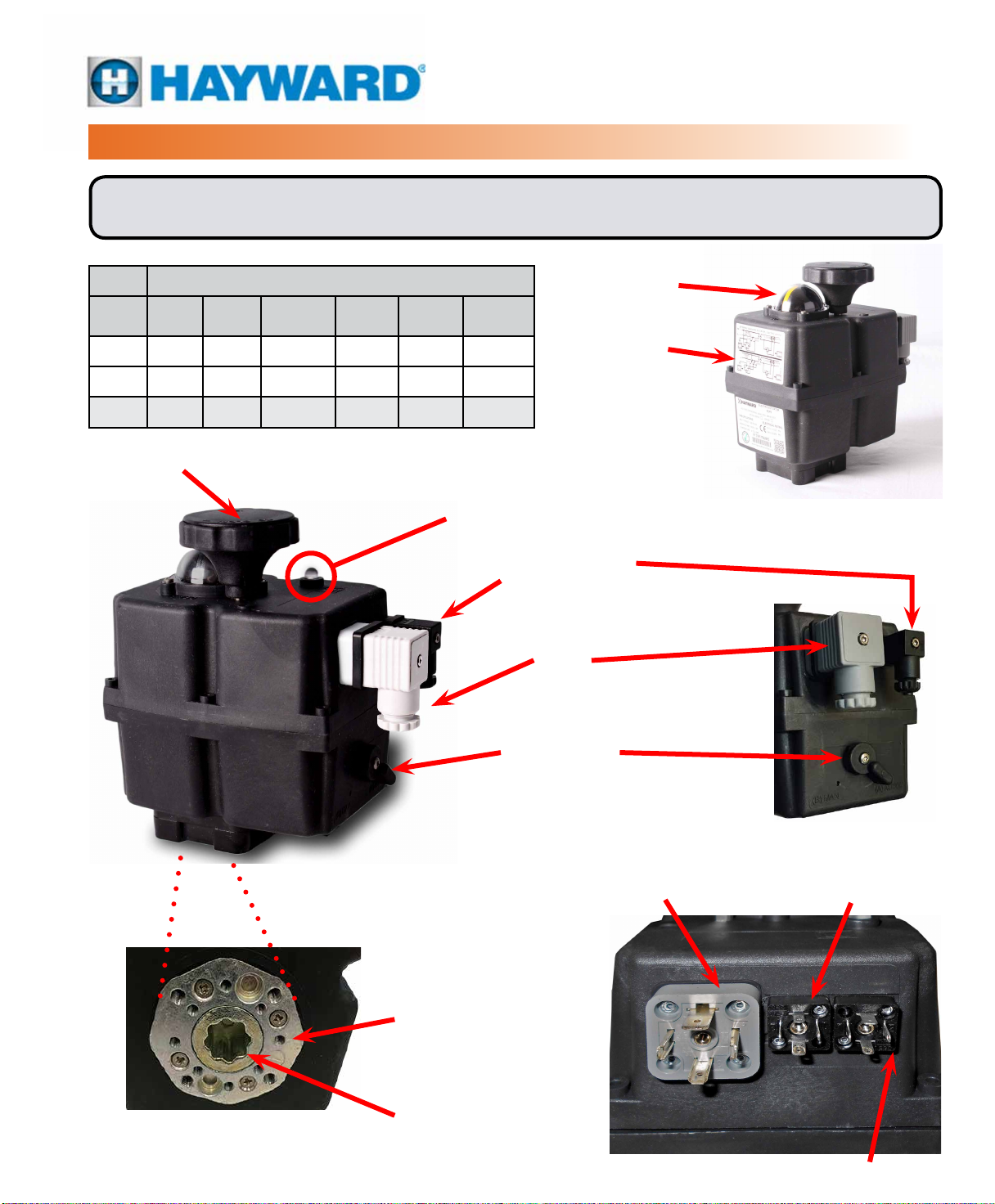
ECP COMPONENT IDENTIFICATION
Notice: ECP Series Manual Override Handwheels rotate CW to close the output shaft out
the bottom of the actuator when viewed from above except the ECP8, see the table below.
Rotation
Model
ECP3 CW CW CW CCW CCW CCW
ECP5 CW CW CW CCW CCW CCW
ECP8 CCW CW CW CW CCW CCW
Hand
wheel
Output
Shaft
Indicator
Hand
wheel
Output
Shaft
Indicator
MANUAL OVERRIDE HANDWHEEL
Note - See table above for handwheel
rotation information by actuator model.
OPERATIONAL STATUS LED
POSITION INDICATOR
PRODUCT LABELS
VOLT FREE AUXILIARY
SWITCH PLUG
POWER SUPPLY
PLUG
DECLUTCH LEVER
(ECP3 Actuator Shown)
(On/Off Actuator Shown)
ISO 5211
MOUNTING FLANGE
14mm Double Square (DSQ)
Drive Socket
POWER SUPPLY
PLUG
(Proportional Model)
(On/Off Actuator Shown)
INPUT / OUTPUT SIGNAL PLUG
(4-20mA, 2-10V, 0-10V)
VOLT FREE AUXILIARY
SWITCH PLUG
QUICK REFERENCE GUIDE
MODELS: ECP3, ECP5 & ECP8
On/Off and Proportional Control
24~240V
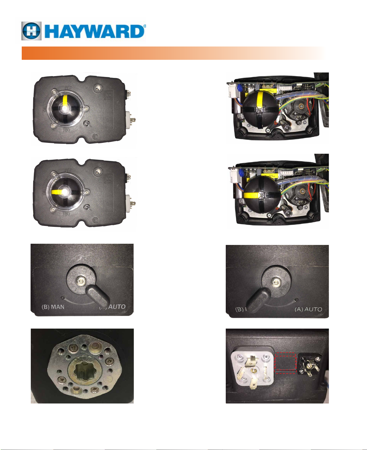
ECP Series shown at 0° rotation
(FULL CW Position) with
cover ON and with cover OFF.
ECP Series shown at 90° rotation
(FULL CCW Position) with
cover ON and with cover OFF.
ISO 5211 Mounting on the bottom surface
for ECP products. Hole patterns included are
F03, F04 & F05 with 14mm DSQ drive socket
for the ECP 3 and F05 & F07 with 14mm
DSQ drive socket for the ECP 5 and ECP 8.
ECP Series shown with Declutch
Lever in the (A) AUTO position (left)
and the (B) MAN position (right).
Note: always remove power
before using the (B) MAN mode.
All electrical connections are made to the
DIN Connectors. Large grey is for power
and control. Small black is for Auxiliary
Switch outputs. Proportional actuators
have a third DIN Connector (center).
ACTUATOR HANDLING AND INSTALLATION
SHIPPING AND HANDLING
1. This actuator arrives in the FULLY OPEN (CCW) position. The yellow position
indicator (see photo) shows full CCW (90°) position.
2. Storage: This unit should not be stored outside unless it is powered up and
has proper electrical terminations. When not powered up, it should be stored
in a clean, dry environment at all times.
3. This actuator has been factory tested and calibrated to operate between 0°
and 90°. Most products will not require recalibration of these settings. If any
travel adjustment is necessary, please refer to the Adjusting CW/CCW End
of Travel section for instructions.
4. Notice: The ECP series actuators have NO mechanical stops to limit rotation.
Do not operate with a rotation greater than 90° unless it has been properly
calibrated to do so.
5. Notice: Protect the actuator from moisture by supplying power to the unit to
keep the internal heater warm at the time of installation.
• For On/Off actuators, in order to keep the 3.5W internal condensate
heater powered up, the actuator needs to receive a continuous OPEN or
CLOSED command at all times.
• For modulating actuators, power on terminals 1 & 2 at all times provides
the required power for the heater.
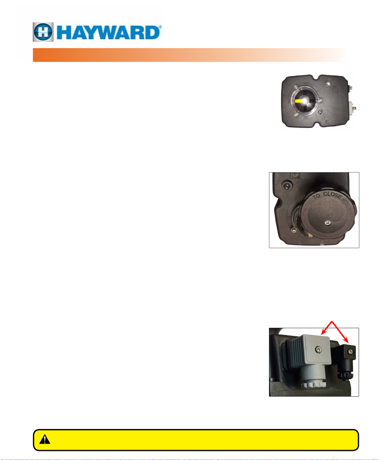
The actuator is shipped (assembled to
a valve) from the factory in its fully CCW
(90° OPEN) position. The YELLOW stripe
indicates the position of the actuator.
INSTALLATION NOTES
• There are no mechanical stops on the ECP series. Use caution when
operating the manual override. Rotating the drive beyond its intended
rotational angle will cause erratic operation under power. Keep the yellow
stripe between the established rotation angles – in most cases 0° to 90°.
• These actuators are designed to be used between a horizontal and
upright position. Do NOT mount the assembly with the actuator top
below a horizontal position (i.e. upside down).
• Notice: Use the DIN connectors supplied with the actuator for eld wiring.
• Use supplied DIN connectors and gaskets during installation to protect
the IP67 integrity of the housing.
• The internal heater is to be used in ALL applications.
• Do NOT install the actuator outdoors or in humid environments unless it
is powered up and the heater is functioning.
• Use proper wire size and cable sheath diameter to prevent actuator
failure (see Wire Sizing Chart on page 4 for proper wire sizing).
• Notice: Parallel wiring of multiple on/off actuators is permissible on the
ECP Series.
• ECP Series On/Off actuators utilize two DIN EN 175301-803 connectors
for power and control to simplify eld wiring and testing. ECP Series
Proportional actuators utilize three DIN EN 175301-803 connectors.
The manual override handwheel (ECP3/5
shown), allows a user to position the
valve or damper with or without power.
The arrow molded in the handwheel
cover shows the direction you must turn
the handwheel to close the actuator
and attached device (ECP8 is reversed).
DIN Connectors
Removable DIN EN 175301-803
connectors facilitate ease of eld
wiring and testing.
WARNING – To avoid dangerous or fatal electrical shock, turn OFF power to all
electrical equipment before working on electrical connections.
 Loading...