

Page 1
Quick
Reference Guide
MENU
<
<
<
1000 rpm
THP 2.70 / 230V
Single Phase 60Hz
Default Speeds
1750 rpm
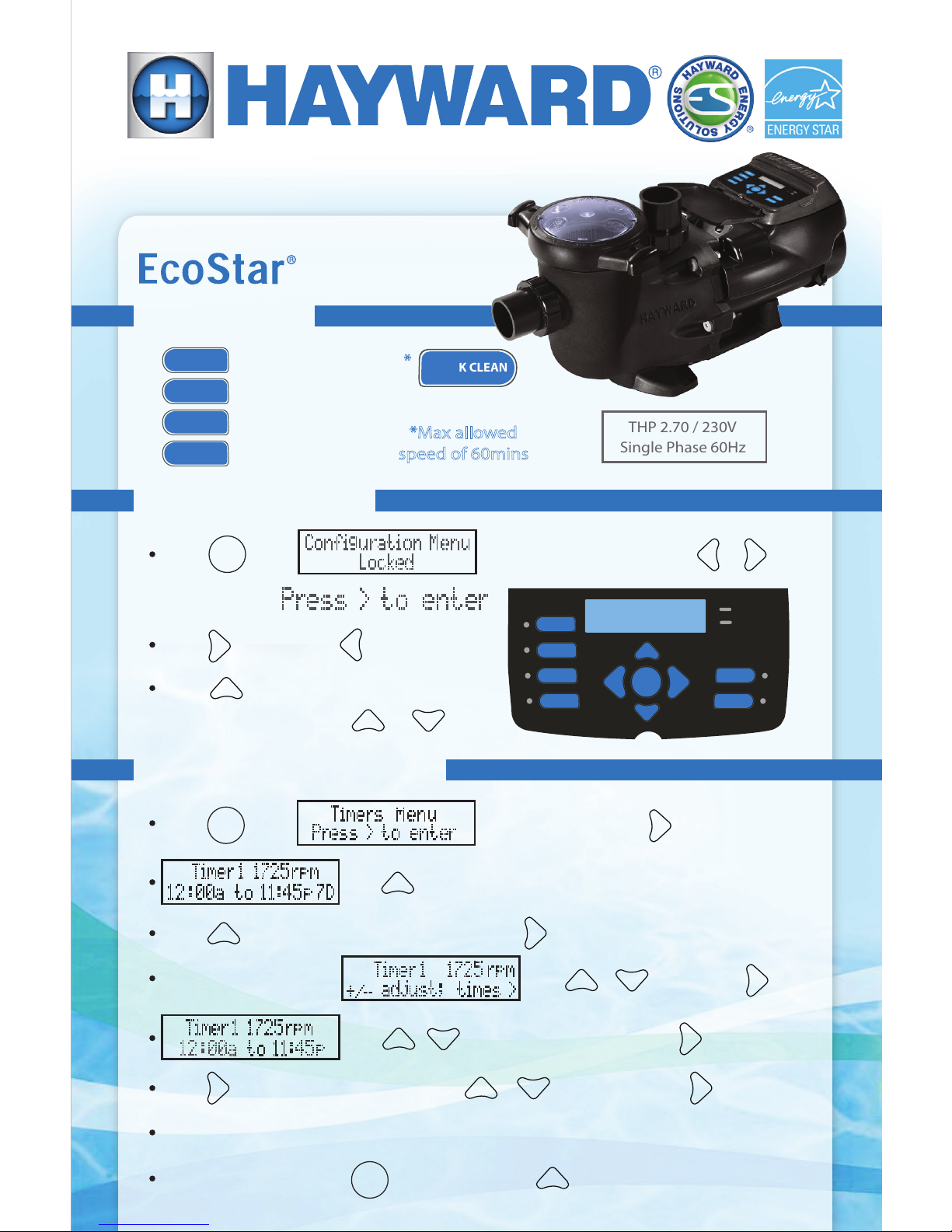
Conguration Menu
Push
until
until you see
Press to advance,
2500 rpm
3250 rpm
STOP/RESUME
QUICK CLEAN
CHECK
SYSTEM
TIMERS
ACTIVE
SPEED 1
SPEED 2
SPEED 3
SPEED 4
MENU
<
<
+
-
SPEED 1
SPEED 2
SPEED 3
SPEED 4
=
=
=
=
QUICK CLEAN
MENU
appears, then hold down
&
Press to edit items, ashing items
to back up
are changed using the or
<
+
-
+
<
Timers Menu - Stand Alone
Push
until
appears, then press
+
use
Push
+
to change timer name, then press <to advance
Next set Timer speed
<
use
then press
/
+
-
use
/
+
-
to modify start time, then <to adjust end
Push
<
to view schedule days, use
/
+
-
to modify, then
To save changes, press
Repeat this process until all desired timers are set
to exit, and then
3250 rpm
*Max allowed
speed of 60mins
*
<
to review
MENU
+
to save
to modify
Page 2
Quick
Reference Guide -
External Control
To take a closer look or see other Hayward products please go to:
www.hayward.com or call 1-800-432-8387
QRG3401VSP (Rev. A)
COMBUS
WALL MOUNT DISPLAY
12345678
INP1
12 VAC
M O T O R
RED BLU BLK
INP2 INP3 INP4
CAUTION
HIGH
VOLTAGE
ABC D E F G H
PWR OUT
DATA
INPUTS
OUTPUTS
L1 L2/N
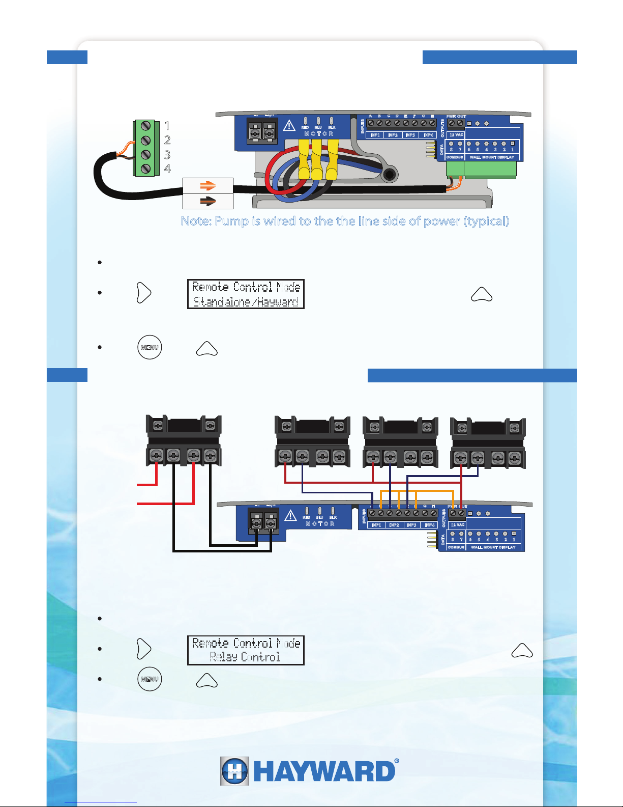
Connecting EcoStar for Relay Control
Connecting EcoStar to Hayward Automation
Locate and unlock Conguration Menu (instructions on front)
Press
<
until if shows “Relay Control” press
+
Press
MENU
then
+
to save any changes
COMBUS
WALL MOUNT DISPLAY
12345678
INP1
12 VAC
M O T O R
RED BLU BLK
EcoStar Wiring CompartmentController (RS485)
Note: Pump is wired to the the line side of power (typical)
1. Connect with shielded 300V communciation wire (utilizing a twisted pair):
2. Verify pump is congured for Hayward Control:
1
2
3
4
2 7
3
8
INP2 INP3 INP4
1. Power pump through lter relay:
FILTER
Relay
240VAC
from
breaker
2. Wire low voltage circuits for each relay with 300V rated conductors
Locate and unlock Conguration Menu (instructions on front)
Press
<
until if shows “Standalone/Hayward” press
+
Press
MENU
then
+
to save any changes
3. Verify pump is congured for Relay Control:
4. Set speeds under the ‘Timer’s Menu’
3. Set pump address according to automation system conguration
CAUTION
HIGH
VOLTAGE
ABC D E F G H
PWR OUT
DATA
INPUTS
OUTPUTS
L1 L2/N
 Loading...