

Page 1
Hayward
ECOMMAND
Automation
Operation Manual
www.haywardnet.com
Page 2

IMPORTANT SAFETY INSTRUCTIONS
When using this electrical equipment, basic safety precautions should always
be followed, including the following:
•
•
•
•
• A green colored terminal marked “Earth Ground” is located inside the wiring
• One bonding lug for US models (two for Canadian models) is provided on the
READ AND FOLLOW ALL INSTRUCTIONS
W ARNING: Disconnect all AC power during installation.
!
W ARNING: Water in excess of 100 degrees Fahrenheit may be
!
hazardous to your health.
W ARNING: To reduce the risk of injury , do not permit children to
!
use this product unless they are closely supervised at all times.
compartment. To reduce the risk of electric shock, this terminal must be
connected to the grounding means provided in the electric supply service
panel with a continuous copper wire equivalent in size to the circuit
conductors supplying the equipment.
external surface. To reduce the risk of electric shock, connect the local
common bonding grid in the area of the swimming pool, spa, or hot tub to
these terminals with an insulated or bare copper conductor not smaller than 8
AWG US / 6 AWG Canada.
• All field installed metal components such as rails, ladders, drains, or other
similar hardware within 3 meters of the pool, spa or hot tub shall be bonded
to the equipment grounding bus with copper conductors not smaller than
8 A WG US / 6 AWG Canada.
• SAVE THESE INSTRUCTIONS
Page 3

Table of Contents
System Overview Block Diagram....................................................................... 1
Automation............................................................................. 1
Default Display ....................................................................... 2
Manual System Filter Pump............................................................................. 3
Operation Lights and Optional Aux1 Outputs........................................ 4
Service.................................................................................... 4
Automatic System Using the Programming Buttons.......................................... 5
Operation Programming Menu Flow Chart........................................... 6
(Programming) Settings Menu........................................................................ 7
Timers Menu........................................................................... 9
Configuration Menu............................................................... 11
Quick “How To” Operate the Pool or Sp a - Manually ..................................... 18
Guide Operate the Pool or Sp a - Automatically ............................. 18
Set the Heater T emperature................................................. 18
Program a T imeclock............................................................ 18
Program a Countdown T imer............................................... 19
Enter/Exit Service Mode....................................................... 19
Troubleshooting & Service Mode ....................................................................... 20
Diagnostic Information Check System Indicator ........................................................ 20
Diagnostic Menu................................................................... 21
Warranty ECOMMAND Warranty .............................................................24
Page 4
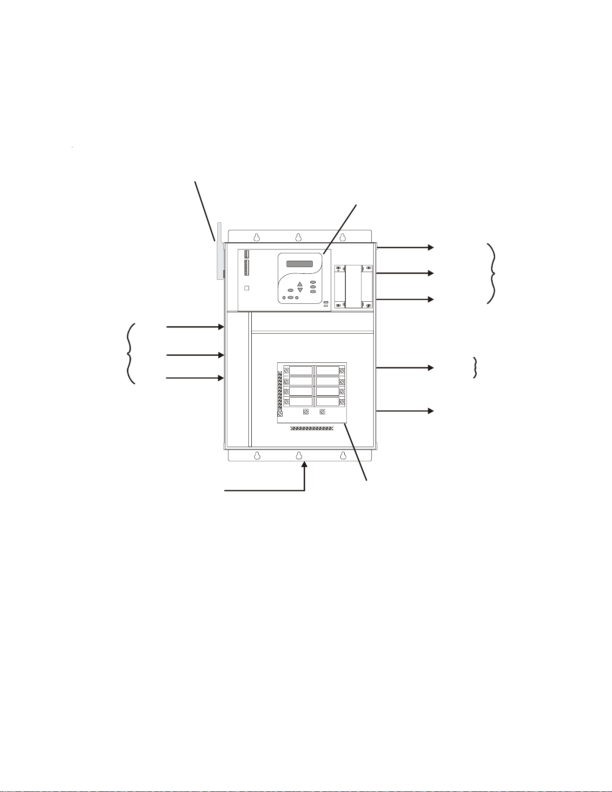
System Overview
The ECOMMAND is a multifunction pool controller used to fully manage your pool/spa system. It can
control pumps, valves, lighting, and heaters. Although the ECOMMAND is easy to use, it is important to
completely read through this operating manual before attempting to operate the control.
Optional
Wireless Base
Receiver
Main Display
Keypad
Filter Pump
Temperature
Sensors
Water
Air
Solar
(optional)
240 VAC
Power
Circuit Brea ke r
Subpanel
Lights
Aux 1
(requires optional
AQL-RELAY-DC-KIT)
Valve 3
Heater
120/240V
Relays
24V Valve
Actuator
NOTE: This manual assumes that the ECOMMAND has been wired and configured according to the
Installation Manual. Aspects of the ECOMMAND that pertain to system setup are not covered in this
manual.
Automation
The ECOMMAND can control up to 3 high voltage (120/240V) pieces of equipment, an automatic valve
actuator, and a conventional and solar heater . Both manual and automatic (programmed) operation are
available. All of the control functions can be programmed at the display/keypad which is part of the main
unit (typically located near the pool equipment). In addition, some functions can be controlled remotely
using an optional HPC-2-RF-KIT remote control kit.
1
Page 5
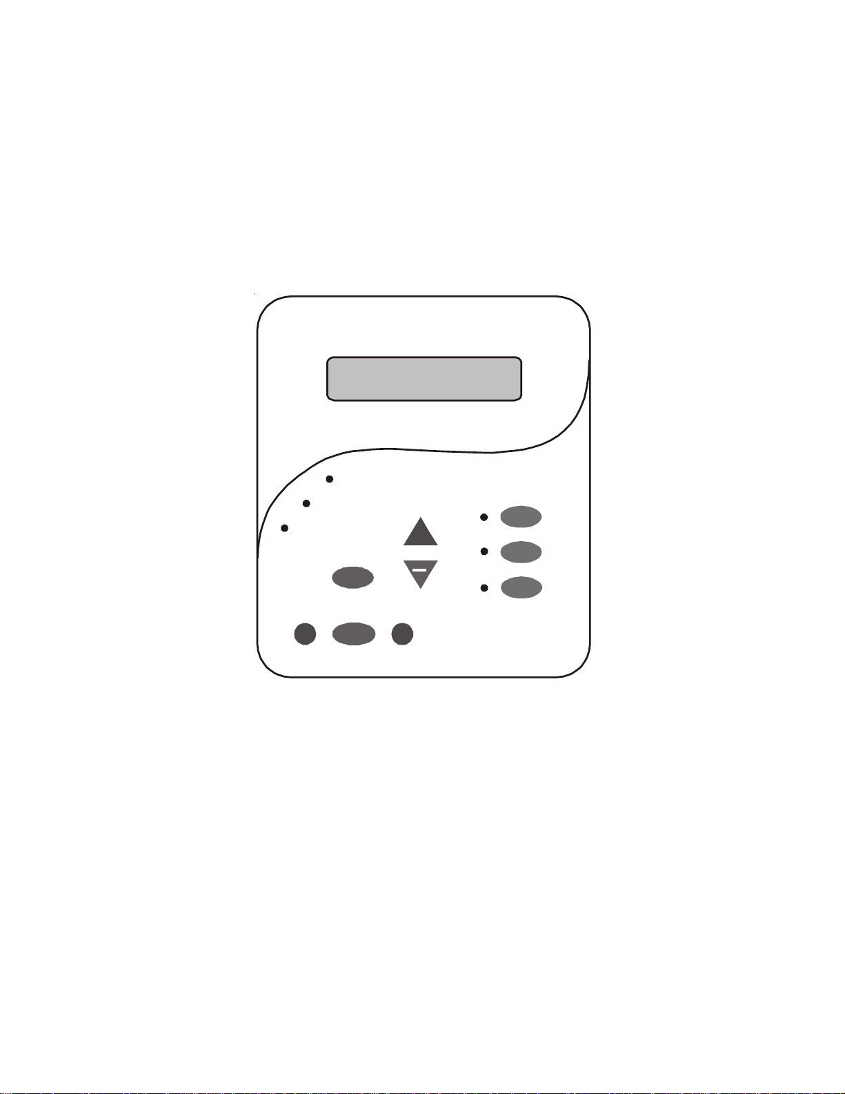
Default Display
Turn power on at the main panel and turn the ECOMMAND control power circuit breaker on. The
keypad will show the default display . The default display alternates between the day/time, air and water
temperature. Under certain circumstances, additional displays may be added to the default menu to inform
you about system operation. Refer to the Programming Menu Flowchart on page 6 to view all possible
displays. The ECOMMAND will automatically scroll through all of the available default menu displays
or you can press “<” or “>” to manually scroll.
Saturday
11:45A
Pool/Spa
>
Service
Menu
Filter
+
Lights
Aux 1
Aux 2
>
2
Page 6
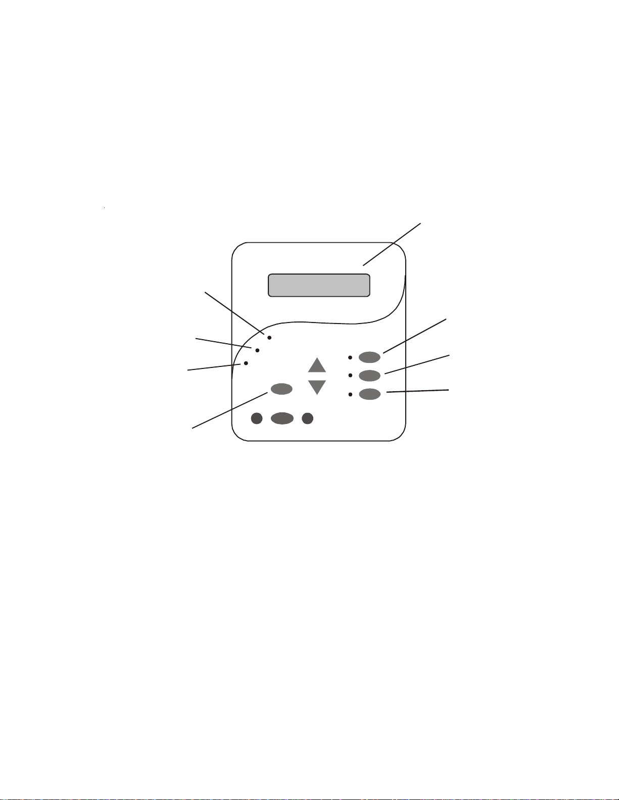
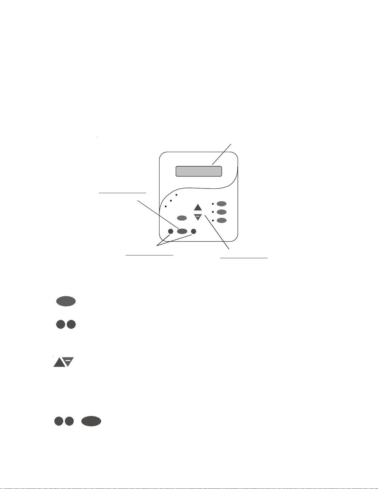
Manual System Operation
While the main objective of the ECOMMAND is to automate the operation of your pool/spa system,
there may be certain times when you want to override the automatic operation and control the equipment
manually . T o operate the pool equipment manually while keeping the automation active, perform the
following procedures. Note that if you turn a relay on manually , it will remain on until either you turn it off
manually , or the next time the programmed automatic operation would normally turn that relay off. Example: the filter pump is programmed to run from 9:00A to 5:00P daily . If you turn the filter pump on
manually at 8:00PM, it will run continuously until the next day at 5:00PM at which time it will turn off and
follow the normal program from then on. Manually turning off a relay works in a similar fashion.
Display
Heater Indicator
Settings
Menu
Filter Pump
Valve 3
Indicator
Check System
Indicator
Service
Pool/Spa
Filter
Lights
Aux 1
(On/Off)
Lights
(On/Off)
Aux 1
(On/Off)
Service But ton
(main display only)
Filter Pump
Single Speed Filter Pump: If the pump is currently off, press the FIL TER button to turn on the pump.
Pressing the FIL TER button again will turn off the pump. However, if there is a heater in the system, and
it is operating, and the “Heater Cooldown” feature is enabled (Configuration Menu) then: when you press
the FIL TER button to turn off the filter, only the heater will turn of f, the Filter LED will flash and the display
will indicate “Heater Cooldown”. At this point the filter pump will automatically turn of f after 5 minutes of
heater cooldown operation. If you want to override the heater cooldown, simply press the FIL TER button
again to turn off the filter pump.
T wo Speed Filter Pump: If the pump is currently off, simply press the FIL TER button to turn on high
speed operation of the filter pump. The “Filter” LED will illuminate continuously . Pressing the FIL TER
button again will switch to low speed operation and the “Filter” LED will flash. If you attempt to switch to
low speed shortly after turning on high speed the filter pump will automatically remain in high speed for 3
minutes before switching to low speed to allow the pump to prime and establish normal water flow .
Freeze Pr otection: This function protects the pool, plumbing, and equipment against freeze damage. If
Freeze Protection is enabled and the AIR temperature sensor falls below the preset freeze protection
temperature (see Filter Pump Configuration), the ECOMMAND will turn on the filter pump to circulate
the water.
3
Page 7

Lights Output & Optional Aux1 Output
Standar d Relay: Manual operation of both relays is identical. Assuming that the relay is currently of f,
simply press the appropriate button to turn on the relay . If the relay does not turn on, it probably is due to
the “interlock” feature (which was set up in the Configuration Menu) being activated that requires the filter
pump to be running and the valves to be in the pool-only position. This protects pumps and other equipment from possible damage. If the controlled output is on, pressing the appropriate button again will turn
off the relay . Manual turn off is disabled if the “Freeze Protection” feature is enabled and the air temperature is less than the selected freeze temperature threshold.
Dimmer Relay: If the Lights or optional Aux1 output is configured as a dimmer , pressing the corresponding button will generate a temporary display which shows the dimmer output level (Off - On 100%).
Pushing the “+” or “-” button changes the level in increments of 20%. When the desired output level is
displayed, press the corresponding button again to turn off the display and return to normal operation.
When the Lights or Aux1 output comes on again (either manually or automatically), the dimmer output level
will be the same as the last time that it was set.
Service
The main unit keypad has a SER VICE key . This button is used primarily during servicing of the pool
equipment. If you want to completely disable the automatic operation and operate the system manually ,
you can put the system into Service or Service-Timed mode by pressing the SER VICE button. Pressing
the SER VICE button once will switch the system into service mode which means that all automatic functions are disabled, and the HPC-2-RF-KIT optional remote control is disabled (except for manual turn off
for emergencies). The red SER VICE LED will be illuminated and the ECOMMAND will remain in this
mode of operation until manually taken out of service mode.
Pressing the SER VICE button again will cause the ECOMMAND to switch to service-timed mode which
is very similar to service mode, except that the ECOMMAND will automatically return to normal operation after 3 hours. During service timed operation, the “Service” LED will flash and the time remaining will
be displayed on the remote display/keypad(s).
Pressing the SER VICE button again, will return the ECOMMAND to normal (automatic) operation. See
Troubleshooting/Diagnostic Information (page 20) for more information about the service modes.
4
Page 8
Automatic System Operation
>
>
>
>
+
The ECOMMAND controls most of your pool equipment automatically in order to minimize the time
spent working on your pool. Most of the pool equipment can be programmed to operate on a timeclock
basis. In addition, the desired water temperature and settings can be programmed. This section will guide
you on how to program the automatic operation for each function.
The programming of automatic functions can be performed at either the main display/keypad located at the
pool equipment pad or the in-home remote display/keypad.
Using the programming buttons
There are 5 buttons on each keypad that are used for programming (refer to diagram).
Display
Settings
Menu
Menu Button
Select Desired Menu
+
>
Menu
>
“<” and “>” Buttons
Select Items from
a Menu
“+” and “-” Buttons
Adust
There are 4 steps to programming any function:
1.
Menu
Press the “MENU” button to get to the desired menu. Multiple pushes of the
button will rotate through all 5 menus and return to the starting point.
2.
Press either key to scroll through the various items in the selected menu. Multiple
pushes of the button will rotate through all menu items and return to the starting
point. Only menu items that are applicable to your pool will appear. (Example: if
you don’t have a spa, then no spa related menu items will appear).
3. Once a menu item has been selected above, the current setting/selection will appear (flashing) on the display . Use the “+” and/or “-” keys to change this selection. Sometimes “+” and “-“ will adjust a value up or down (example: heater
temperature setting or timeclock on/off time). In this case, pushing the “+” or “-”
will change the value by one increment and holding the “+” or “-” button in for
more than one second will make the values auto scroll. In other cases, the “+” and
“-“ may toggle between 2 options.
4.
Menu
After you have adjusted the item to the desired value, simply move on to the next
menu item to “lock in” your new setting. The ECOMMAND memory will maintain the setting, even if power is removed for an extended period.
5
Page 9
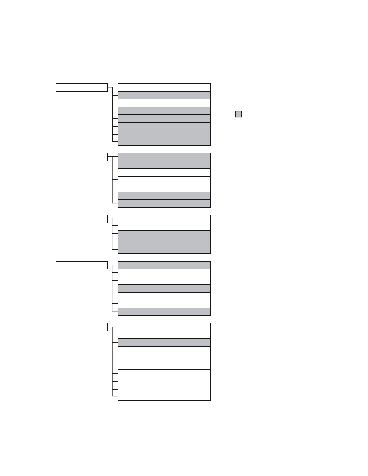
Programming Menu Flowchart
The ECOMMAND’s five menus have many items in each menu that allow you to customize the operation
of your pool/spa equipment. The chart below shows the ECOMMAND’ s five menus as well as each
menu’ s specific settings
default menu
settings menu
timers menu
day and time
water temperature
air temperature
reason pump is running (not scheduled)
reason hi-speed is running (not schedul ed)
countdown time remaining
heater control status
check system e rror
heater1 temperature
solar temperature
day and time
backlit display light
beeper
teach wireless remote
wireless channel
filter pump1 or hi-speed
filter pump2 or lo-speed
lights
aux1
valve3
denotes conditional items
diagnostic menu
configuration menu
flow switch
water sensor
air sensor
solar sensor
main softwa re revision
display software revision
RF base software revision
filter
heater1
solar
lights
aux1
valve3
7-day or weekend/weekday timeclock
12 hour or 24 hour time format
ºF or ºC
reset to default
6
Page 10

The Default Menu is a series of informative displays with nothing to set. The ECOMMAND will automatically switch to the default menu when no keys have been pressed for 2 minutes and will then scroll through
each display .
The Settings Menu and the Timers Menu are the menus you will be using most often to adjust the operation
of your pool. The Configuration Menu is used when the system is installed and defines what equipment is
connected to each output and the operational logic that will control the equipment. This menu is normally
“locked” and should only be used by a pool professional. Details regarding the Configuration menu are
included in both the Operation and the Installation Manual.
The “Diagnostic Menu” is primarily intended for the service technician and contains information and details
about the system operation that are helpful in troubleshooting, if problems occur.
Settings Menu
The Settings Menu allows you to set all system operating parameters except the timeclock and countdown
timers which are part of the Timers Menu.
Adjust the desired water temperature (Off, 65°F, 66°F, ...103°F, 104 °F, Off)
Water Heater1
Off
+
>
Move to previous/next menu item
>
The water heater setting will only appear if the heater control is enabled. The heater will turn
on whenever the filter pump is running and the water temperature is less than the desired
temperature setting. If you have both solar heat and a conventional heater and the solar
priority option is selected (Configuration Menu), then the conventional heater will only
operate when solar heat is NOT available.
Solar
88°F
Set Day and Time
Set Day and Time
Wednesday 10:37P
10:37P
Set Day and Time
Wednesday
Set Day and Time
Wednesday
10: P
37
Adjust the desired water temperature (Off, 65°F, 66°F, ...103°F, 104°F, Off)
+
>
Move to previous/next menu item
>
The solar setting will only appear if the solar control is enabled. The solar system will turn on
whenever the filter pump is running and the water temperature is less than the desired
temperature setting and solar heat is available.
Adjust the current day of the week
Adjust the current day of the week
+
+
>
>
Move to hours settin g
Move to hours settin g
>
>
Adjust the current hour (including AM/PM, if applicable)
+
>
Move to minutes setting
>
Adjust the current minute
+
>
Move to previous/next menu item
>
Use this function to set the current day of the week and time. These values are used for all
the automatic timeclock functions of the ECOMMAND and are also displayed as part of the
default menu.
The ECOMMAND is designed to keep the clock running during power outages lasting less
than 7 days. If power has been off for longer than 7 days, then the time may have to be reset.
7
Page 11

Display Light
On for 60 sec.
Toggle between Always On and On for 60 sec.
+
>
Move to previous/next menu item
>
This function controls the backlight on the display. If the “60 seconds” option is selected,
then the backlight will automatically turn off 60 seconds after the last key is pressed and will
stay off until next time a key is pressed.
Note that the Display Light selection only applies to the display keypad that you are currently
using. Other display/keypads will not be affected. In other words, you need to individually
set this option for each display/keypad in the system.
Beeper
Enabled
Teach Wireless
+ to start
Press and hold
wireless button
Teach
Wireless
Successful
Teach
Wireless
NOT Successful
Teach Wireless
Base NOT Found
+
Toggle between Beeper Enabled (default) and Disabled
>
Move to previous/next menu item
>
When “Enabled”, the keypad will beep every time a key is pressed. If this is not desired,
select “Disabled”.
+
Push to start process
>
>
Move to previous/next menu item
Press any button on wireless remote
>
>
Move to previous/next menu item
>
Move to previous/next menu item
>
>
Move to previous/next menu item
>
This menu will only appear if a wireless base station is connected to the ECOMMAND.
Perform this procedure each time a wireless remote control is added to the ECOMMAND
system. During this procedure the wireless remote “learns” and remembers the ID code for
the wireless base station connected to this particular ECOMMAND unit and will reject
messages with any other ID codes. If “Base NOT found” is displayed, then the ECOMMAND
can not communicate with the transmitter/receiver base station attached to the main unit. If
“NOT Successful” is displayed, then the base station did not receive a signal from the
remote control. This may be due to the distance between the Base Receiver and the remote
device being too great or may be due to interference caused by other RF equipment operating in the neighborhood. Try changing the channel and then repeat the “Teach Wireless”
command.
Wireless
Channel: 1
Confirm Change:
+ to proceed
Reteach all
wireless units
Change the desired wireless channel (1 - 5)
+
>
If channel is changed, move to confirmation menu
>
>
If channel is not changed, move to previous/next menu item
Push to confirm the channel change
+
>
>
Move to previous/next menu item
>
>
Move to previous (Teach Wireless) menu
>
This setting changes the channel to be used by the wireless base station and remote(s). If
the channel is changed and confirmed, all of the wireless remotes will have to be retaught.
This menu will only appear if a wireless base station is connected to the ECOMMAND.
8
Page 12

Timers Menu
The Timers Menu allows you to set all timeclock and countdown timers which control the automatic
operation of your pool/spa system.
Each timeclock has a single on/off program per day . All of the timeclocks are setup (Configuration Menu)
either as “all days” or “weekends/weekdays”. If “weekends/weekdays” are selected, you will need to
program on times for both weekdays and weekends and off times for both weekdays and weekends, even
if you want them to be the same. All times are adjusted in 15 minute increments (9:00A, 9:15A, 9:30A,
etc.). If you program the on time equal to the off time (“10:00A to 10:00A”) the output will NEVER turn
on. If you want to disable a timeclock, you can set the on time equal to the off time and you will notice the
times disappear and the display simply shows “Off”. If, at a later time, you wish to re-activate the timeclock,
simply press either the “+” or “-” buttons to go back to a normal timeclock programming display .
The Countdown timer is programmed in increments of 5 minutes from “Manual On/Off” (0 minutes) to a
maximum of “21:00” (21 hours). When “Manual On/Off” is displayed, the countdown timer is disabled
and the output will be manually controlled. When a countdown timer is equal or greater than “0:05”,
pressing the appropriate output button will turn the output on and start the timer . Pressing the button again
will turn the output off or , when the programmed time has elapsed, the output will automatically turn off.
Adjust time setting
Set Day and Time
Filter T1-all
Wednesday 10:37P
or
8:30A to 4:00P
Filter T1-wkend
8:30A to 4:00P
Adju s t tim e s
+
+
>
>
Move between start and stop times & to previous/next menu item
>
>
Adjust time setting
+
>
Move between start and stop times & to previous/next menu item
>
Filter T1-wkday
8:30A to 4:00P
Set Day and Time
Filter T2-all
Wednesday 10:37P
or
8:30A to 4:00P
Filter T2-wkend
8:30A to 4:00P
Filter T2-wkday
8:30A to 4:00P
Adjust time setting
+
>
Move between start and stop times & to previous/next menu item
>
For one speed pumps, this is the first filter timeclock and will determine the normal hours of
filtration for the pool. For pool/spa combination systems with spillover enabled, the valves
will automatically switch to spillover mode at the start of the filtration period. For all other
systems, the valves will switch to the pool-only position. Refer to the text above for general
notes regarding timeclock programming.
For two speed pumps, this setting will be the period of time when the pump runs at high
speed (the word “Filter T1” in the display will be replaced with “Filter Hi”). There is a
separate timeclock for the low speed operation (see “Filter T2” below). If the high speed and
low speed periods overlap, then the pump will operate in low speed during the overlap
period.
There are several reasons the filter pump may be running at times other than the timeclock
period set above. These include manual operation, heater cooldown, freeze protection and
“solar-extend”.
Adjust time setting
Adju s t tim e s
+
+
>
>
Move between start and stop times & to previous/next menu item
>
>
Adjust time setting
+
>
Move between start and stop times & to previous/next menu item
>
Adjust time setting
+
>
Move between start and stop times & to previous/next menu item
>
For one speed pumps, this is the second filter timeclock
For two speed pumps, this timeclock will set the normal time period for filter pump low speed
operation (the word “Filter T2” in the display will be replaced with “Filter Lo”). If the filter
pump was off prior to the start of this time period, the filter pump will first turn on at high
speed for 3 minutes to prime and establish water flow. Afterwards, it will drop down to low
speed for the remainder of the programmed low speed time period. While this time clock will
9
Page 13

Set Day and Time
Wednesday 10:37P
or
8:00P to 11:00P
Lights-wkend
8:00P to 11:00P
Lights-all
override the high speed timeclock (see above), there are several reasons why the pump will
automatically switch to high speed operation during this programmed time period. These
include manual operation, spa operation, or heating operation. Refer to page 9 for general
notes regarding timeclock programming.
Adjust time setting
Adju s t tim e s
+
+
>
>
Move between start and stop times & to previou s/next menu item
>
>
Adjust time setting
+
>
Move between start and stop times & to previou s/next menu item
>
Lights-wkday
8:00P to 11:00P
This menu will appear only if the Lights are configured for timeclock. The lights will turn on
or
Lights-CountDn
0:20
If Aux1 is enabled. Note that the Aux1 function requires the use of the optional AQL-RELAY -DC-KT .
Set Day and Time
Aux1-all
Wednesday 10:37P
or
8:30A to 4:00P
Aux1-wkend
8:30A to 4:00P
and off at the designated times. The only override on this function is manual on/off control
by the “Lights” button.
This menu will appear only if the Lights are configured for countdown timer. This setting is
the time after you manually turn on the lights until the ECOMMAND automatically turns off
the lights. You can also manually turn off the lights at an earlier time by pressing the LIGHTS
button. If the Lights relay is on during the programmed off time, it may be because of freeze
protection.
Adjust time setting
+
>
Move between start and stop times & to previou s/next menu item
>
Adjust time setting (Manual On/Off, 0:05, 0:10, 0:15...)
+
>
Move to previous/next menu item
>
Adjust time setting
Adju s t tim e s
+
+
>
>
Move between start and stop times & to previous/next menu item
>
>
Adjust time setting
+
>
Move between start and stop times & to previous/next menu item
>
or
Aux1-wkday
8:30A to 4:00P
Aux1-CountDn
0:20
Adjust time setting
+
>
Move between start and stop times & to previous/next menu item
>
This menu will appear only if the Aux1 is configured for timeclock. The Aux1 output will turn
on and off at the designated times. If the Aux1 relay is off during the programmed on time—
note that some pool equipment (example pressure side pool cleaner) can only be operated
when the filter pump is running and the pool/spa valves are in the pool-only position—the
ECOMMAND will keep the relay off until these other conditions are suitable for operation.
If the Aux1 relay is on during the programmed of f time, it may be because of freeze protection.
Also, manual operation overrides the timeclock.
Adjust time setting (Manual On/Off, 0:05, 0:10, 0:15...)
+
>
Move to previous/next menu item
>
This menu will appear only if the Aux1 is configured for countdown timer . This setting is the
time after you manually turn on the Aux1 relay until the ECOMMAND automatically turns of f
the relay. You can also manually turn off the relay at an earlier time by pressing the AUX1
button.
10
Page 14

Set Day and Time
Wednesday 10 : 37P
or
8:30A to 4:00P
Valv e 3-wkend
8:30A to 4:00P
Valve3-all
Adjust time setting
Adju s t tim e s
+
+
>
>
Move between start and stop times & to previous/next menu item
>
>
Adjust time setting
+
>
Move between start and stop times & to previous/next menu item
>
Valve3-wkday
8:30A to 4:00P
This menu will appear only if Valve3 is configured for timeclock. The valve will rotate on and
off at the designated times. There is no manual override. If the Valve3 relay is on during the
programmed off time, it may be because of freeze protection.
Adjust time setting
+
>
Move between start and stop times & to previous/next menu item
>
Configuration Menu
The ECOMMAND MUST BE CONFIGURED before attempting to operate. Configuration information
is entered at the keypad and “tells” the ECOMMAND what equipment is connected and how each should
be controlled.
CAUTION: When changing an existing configuration, it is important to understand how
!
the pool system operates and what specific equipment is connected to each output. Incorrect settings in the configuration menu could lead to damaged equipment and improper
operation of the pool system.
Accessing the Configuration Menu
Configuring the ECOMMAND requires that you navigate through the Configuration Menu and input
various information. For more detailed information about using the ECOMMAND menu system, refer to
the Operation Manual.
To access the Configuration Menu
Configuration
Menu-Locked
Configuration
Menu-Unlocked
Menu
Press repeatedly until “Configuration Menu” is displayed
>
>
Press BOTH buttons SIMULTANEO U SLY for 5 seconds to unlock
>
Move to configuration menu
>
NOTE: The configuration menu automatically “locks” after 2 minutes of no buttons being
pressed to prevent unauthorized people from changing the control logic inadvertently and
possibly damaging the pool equipment or causing a “call back” to fix the configuration.
Configuration Menu Items
Each item needs to be programmed and may contain additional sub-menu items. Refer to the following
pages for information on programming.
11
Page 15

Filter Pump Config.
+ to view/change
+
Push to access pump options
>
Move to previous/next configuration menu
>
Filter Pump
1 Speed
Freeze Protect
Enabled
if “Freez e Protect” is e nabled
and “2-s peed Filter” is selecte d
Freeze Protect
High Speed
Freeze Temp
38ºF
Toggle between 1-speed (default) and 2-speed options
+
+
>
>
Move to next menu item
>
>
Toggle between Enabled (default) and Disabled Freeze Protection
+
>
Move to next menu item or previous/next configuration menu
>
Toggle between high speed (default) and low speed
+
>
Move to next menu item
>
Adjust the desired freeze protection temperature (33ºF - 42ºF)
+
>
Move to previous/next configuration menu
>
Filter Pump
Select single speed or 2-speed pump. If a 2-speed pump is configured, either the LIGHTS
relay or an option AQL-RELAY-DC-KT relay must also be configured to control the low
speed motor winding on the pump (in the Installation manual, see page 7 for wiring and page
17 for AUX1 configuration). See the Operation Manual for specific information regarding the
control logic for 2-speed pump operation.
Freeze Protection
Freeze protection is used to protect the pool and plumbed equipment against freeze damage.
If freeze protection is enabled and the AIR temperature sensor falls below the freeze threshold
(see below), the ECOMMAND will turn on the filter pump to circulate the water.
Freeze Protection Speed
This menu only appears if freeze protection is enabled and the pump is configured for 2speed. This is the speed that the pump will run at during freeze protection operation. Select
high (default) or low speed operation.
Heater1 Config.
+ to view/change
Heater1
Disabled
if “Heater 1” is enabled
Heater1 Cooldown
Disabled
if “Heater 1” is enabled
Heater1 Extend
Disabled
if “Heater 1” is enabled and
2-speed f i lt er pump is enabled
Allow Low Speed
Disabled
Freeze Protection Temperature
Select the temperature to be used for freeze protection. T emperature is adjustable from 33ºF
- 42ºF (1ºC - 6ºC). 38ºF (3ºC) is default. This threshold will be used for all outputs that have
freeze protection enabled.
Push to access heater options
+
>
Move to previous/next configuration menu
>
Toggle between Enabled and Disabled (default) Heater 1
+
+
>
>
Move to next menu item or previous/next configurati on menu
>
>
Toggle between Enabled and Disabled (default) Heater 1 Cooldown
+
>
Move to next menu item
>
+
Toggle between Enabled and Disabled (default) Heater 1 Extend
>
>
Move to previous/next configuration menu
+
Toggle between Enabled and Disabled (default)
>
>
Move to next menu item or previous/next configurati on menu
Heater1
If the heater is “Enabled”, the heater relay will turn on when the water temperature is less
than the desired temperature setting and the filter pump is running. The desired temperature
is in the “Settings Menu”.
12
Page 16

Heater Cooldown
This feature ensures that the heater cools down before water circulation is stopped. When
enabled, the ECOMMAND will continue to run the filter pump for 5 minutes after the heater
turns off. During this period the filter pump LED will flash and also a “Heater Cooldown,
X:XX remaining” message will scroll on the display.
When the filter pump is running and the heater is on: Pressing the “Filter” button once will
cause the heater to turn off, but the filter pump will continue to run for heater cooldown (filter
LED flashing and message on display). Pushing the filter button a second time will override
the heater cooldown operation and turn the filter pump off.
Heater Extend
If “Enabled”, the filter extend logic keeps the filter pump running beyond the normal turn-off
time until the water is heated up to the desired temperature setting (see Settings Menu).
Heater extend will NOT cause the filter pump to turn on, it will only delay the turn off time
when the heater is operating.
Allow Low Speed
This menu only appears if the pool filter is configured for 2-speed operation. During default
operation, high speed mode is used whenever the heater is on. If Allow Low Speed is
“Enabled”, low speed will be allowed whenever the heater is on.
Solar Config.
+ to view/change
Solar
Disabled
if “Solar” is enabled
Solar Extend
Disabled
if “Solar” is enabled
Solar Priority
Disabled
if “Solar” is enabled
and “2-s peed Filter” is selected
Allow Low Speed
Disabled
Push to access solar options
+
>
Move to previous/next configuration menu
>
Toggle between Enabled and Disabled (default) Solar
+
+
>
>
Move to next menu item or previous/next configuration menu
>
>
Toggle between Enabled and Disabled (default) Solar Extend
+
>
Move to next menu item
>
+
Toggle between Enabled and Disabled (default) Solar Priority
>
>
Move to next menu item or previous/next configuration menu
>
+
Toggle between Enabled and Disabled (default)
>
Move to previous/next configuration menu
>
Solar
If the solar control logic is “Enabled”, several additional steps must be taken to ensure
proper operation of the solar system. If the solar is operated by a valve, then the Valve3
output must be setup for solar logic (see page 18 in the Installation manual). If the solar is
operated by a pump, then one of the AUX1 relay must be set up for solar logic (see page 17
in the Installation manual). Also, the “solar” temperature sensor must be installed. This
sensor is typically mounted near the collector array and is used to sense whether sufficient
solar heat is available.
If solar is “Enabled”, the valve or solar pump relay will turn on when the water temperature is
less than the desired temperature setting AND the solar sensor is hotter than the water. The
desired temperature is in the “Settings Menu”. If applicable, the homeowner will be prompted
to enter separate pool and spa desired temperature settings. Depending on the position of
the pool/spa suction valve, the proper temperature setting will be used.
Solar Extend
If “Enabled”, the filter extend logic keeps the filter pump running beyond the normal turn-off
time if solar heat is still available. When solar heat is no longer available, both the solar
valve/pump and filter pump will turn off simultaneously. Solar extend will NOT cause the
filter pump to turn on, it will only delay the turn off time when solar is operating.
13
Page 17

Solar Priority
If both “Solar Control” and “Heater Control” are enabled, the Solar Priority feature will keep
the conventional heater off whenever solar heat is available. This provides the most cost
effective way of heating the pool. When solar heat is not available, the conventional heater
will operate normally .
Allow Low Speed
This menu only appears if the pool filter is configured for 2-speed operation. During default
operation, high speed mode is used whenever the solar heater is on. If Allow Low Speed is
enabled, low speed pump operation will be allowed during solar heating except for the first 3
minutes after solar heat turns on.
Lights Config.
+ to view/change
Lights Function
Manual On/Off
for manual on/off, countdown
timer and ti m eclock funct i ons
Lights Relay
Standard
for all functions except solar and
low speed of 2- speed filte r pump and dim m er
Lights Interlock
Disabled
for all functions except
low speed of 2- speed filter pump
Lights Freeze
Disabled
Push to access Lights options
+
>
Move to previous/next configuration menu item
>
Rotates between
+
Solar, and Low speed of a 2-speed pump
>
>
Move to next menu item
+
Toggle between Standard (default) and Dimmer
>
Move to next menu item or previous/next configuration menu
>
Toggle between Enabled and Disabled (default) Lights Interlock
+
>
Move to next menu item
>
Toggle between Enabled and Disabled (default) Lights Freeze Protection
+
>
Move to previous/next configuration menu
>
Lights Function
Although designated as the “Lights” output, the function of the lights relay is similar to the
Aux1 relay . If pool lights are wired to the lights relay, some options including Solar function,
Low Speed of a 2-Speed Filter Pump, Lights Interlock and Lights Freeze Protection will not be
necessary and should be disabled. If no pool lights are used, the lights relay can be used to
control other pool devices that may require these options. The function of each option is
shown below .
Manual On/Off—the lights relay will alternate between turning on and off when the LIGHTS
button is pressed. There is no automatic control logic.
Manual On/Off (default), Countdown Timer, Timeclock,
options
Countdown Timer—the lights relay will turn on when the LIGHTS button is pressed. The
lights relay will turn off automatically after a programmed time (see Timers Menu in Operation
Manual). The LIGHTS button can also be used to turn the output off.
Timeclock – the lights relay will turn-on and turn-off at the times set for the lights timeclock
in the Timers Menu (see Timers Menu in Operation Manual). The LIGHTS button can also
be used to turn the output on and off.
Solar – the lights relay can operate a solar booster pump which will turn on when the filter
pump is running and solar heat is available and the water is less than the desired temperature
setting. It is important to note that “Solar Control” must be enabled in the “Solar Config.”
menu for proper operation to occur.
Low Speed of a 2-speed Filter Pump – the ECOMMAND will turn on the lights relay whenever
the low speed operation of the filter pump is required. It is very important that the “2-speed”
filter pump option be selected under the “Filter Config.” Menu for proper operation.
14
Page 18

Lights Relay
This feature allows the user to select either “Standard” (default) or “Dimmer” type relay for
the Lights output. The optional AQL-DIM dimmer kit must be installed if “Dimmer” is
desired. When “Dimmer” is selected, and the Lights output is manually turned on, the “+”
and “-” buttons adjust the level from 20% to 100% (default). The level is saved for the next
time the lights are turned from off to on.
Lights Interlock
If enabled, this feature will override the function (Manual On/Off, Countdown Timer,
Timeclock) selected above and turn the lights relay off when: filter pump is off, first 3
minutes of filter pump operation (allows the pump to prime and get water flowing), when the
pool/spa suction return valves are in any position other than “pool only”, or for the first 3
minutes after solar turns on (allows air in the solar panels to be purged). Interlock is not
available for solar, low speed filter pump, or dimmer .
Lights Freeze Protection
This function helps protect equipment that is wired to the lights relay against freeze damage.
If Freeze Protection is enabled and the AIR temperature sensor falls below the selected freeze
temperature threshold, the ECOMMAND will energize the lights relay . IMPOR T ANT : this
only enables operation of the lights relay during freeze--see the “Filter Pump Config.” menu
to enable freeze protection for the main circulation system.
Requires the use of the optional AQL-RELAY-DC-KT
Aux1 Config.
+ to view/change
Aux1 Output
Enabled
if Aux 1 is enabled
Aux1 Function
Manual On/Off
for manual on/off, countdown timer
and timecl ock functions if Aux 1 is enabled
Aux1 Relay
Standard
for all functions except solar and low speed of
2-speed f ilter pump and dimm er if Aux 1 is enabled
Aux1 Interlock
Disabled
for all functions except low spee d of
2-speed f ilter pump if Aux1 i s enabled
Aux1 Freeze
Enabled
WARNING: Do not use the ECOMMAND to control an automatic pool cover.
!
Push to access Aux1 options
+
>
Move to previous/next configuration menu item
>
+
Toggle between Enabled and Disabled (default)
>
Move to previous/next configuration menu item
>
Rota te s betw ee n
+
Solar, and Low speed of a 2-speed pump
>
Move to next menu item
>
+
Toggle between Standard (default) and Dimmer
>
Move to next menu item or previous/next confi guration menu
>
Toggle between Enabled and Disabled (default) Aux1 Interlock
+
>
Move to next menu item
>
Toggle between Enabled (default) and Disabled Aux1 Freeze
+
>
Move to previous/next configuration menu
>
Manual On/Off , Countdown Timer, Timeclock,
(default)
options
Swimmers may become entrapped underneath the cover.
Aux1 Output
The ECOMMAND features an optional auxiliary function that can be used to control a
variety of pool equipment. This feature is disabled by default. If the auxiliary function is
desired, the optional AQL-RELAY-DC-KT must be installed and the Aux1 output must be
enabled.
Aux1 Function
Manual On/Off (default)—the aux1 relay will alternate between turning on and off when the
AUX1 button is pressed. There is no automatic control logic.
Countdown Timer – the aux1 relay will turn on when the AUX1 button is pressed and then
will turn off automatically after a programmed time (see Timers Menu, Operation Manual).
The AUX1 button can also be used to turn the output off.
15
Page 19

Timeclock – the aux1 relay will turn-on and turn-of f at the times set for the Aux1 timeclock in
the Timers Menu. The AUX1 button can also be used to turn the output on and off.
Solar – the aux1 relay operates a solar booster pump which will turn on when the filter pump
is running and solar heat is available and the water is less than the desired temperature
setting. It is important to note that “Solar Control” must be enabled in the “Solar Config.”
menu for proper operation to occur.
Low Speed of a 2-speed Filter Pump – the ECOMMAND will operate the aux1 relay whenever
the low speed operation of the filter pump is required. It is very important that the “2-speed”
filter pump option be selected under the “Filter Config.” Menu for proper operation.
Aux1 Relay
This feature allows the user to select either “Standard” (default) or “Dimmer” type relay for
the Aux1 output. The optional AQL-DIM dimmer kit must be installed if “Dimmer” is desired.
When “Dimmer” is selected, and the Aux1 output is manually turned on, the “+” and “-”
buttons adjust the level from 20% to 100% (default). The level is saved for the next time the
Aux1 output is turned from off to on.
Aux1 Interlock
If “Enabled”, this feature will override the function (Manual On/Off, Countdown Timer,
Timeclock), selected above and turn the Aux1 off when: filter pump is off, first 3 minutes of
filter pump operation (allows the pump to prime and get water flowing), when the pool/spa
suction return valves are in any position other than “pool only”, or for the first 3 minutes
after solar turns on (allows air in the solar panels to be purged). Interlock is not available for
solar, low speed filter pump, or dimmer .
Aux1 Freeze Protection
This function protects the pool, plumbing, and equipment against freeze damage. If Freeze
Protection is enabled and the AIR temperature sensor falls below the selected freeze
temperature threshold, the ECOMMAND will turn on the aux1 relay to circulate the water.
IMPOR T ANT: this only enables operation of the aux1 output during freeze--see the “Filter
Pump Config.” menu to enable freeze protection for the main circulation system.
Valve3 Config.
+ to view/change
Valve3 Function
Solar
for all functions except solar
and valve3=x
Valve3 Interlock
Disabled
for all functions except solar
and valve3=x
Valv e 3 Fre e ze
Disabled
Push to access Valve3 options
+
>
Move to previous/next configuration menu item
>
Rotates between Timeclock , Solar, In-Floor Cleaner,
+
and Valve3=Filter , Valve3=Lights, and Valve3=Aux1
>
Move to next menu item
>
Toggle between Enabled and Disabled (default) Valve3 Interlock
+
>
Move to next menu item
>
Toggle between Enabled and Disabled (default) Valve3 Freeze
+
>
Move to previous/next configuration menu
>
Valve3 Function
Timeclock (default) – the valve turns on/off at the times set for the Valve3 timeclock in the
Timers Menu (see Operations Manual).
Solar – the valve operates when the filter pump is running and solar heat is available and the
water is less than the desired temperature setting. Solar heating must be enabled in the
“Solar Config. menu for proper operation to occur.
In-Floor Cleaner – the valve switches the water returning to the pool between the in-floor
cleaner and the normal return jets which facilitate efficient surface skimming. The valve will
operate the in-floor cleaner for the first half of each clock hour and then switch to the jets/
skimming for the last half of the hour.
(default)
16
Page 20

All Timeclocks
7-day
Valve3=Filter – the valve operates whenever the Filter relay is on.
Valve3=Lights – the valve operates whenever the Lights relay is on.
Valve3=Aux1 – the valve operates whenever the Aux1 relay is on.
Valve3 Interlock
If “Enabled”, this feature will override the function (timeclock or in-floor cleaner) selected
above and turn the valve off when: the filter pump is off, first 3 minutes of filter pump
operation (allows the pump to prime and get water flowing), when the pool/spa suction
return valves are in any position other than “pool only”, or for the first 3 minutes after solar
turns on (allows air in the solar panels to be purged). Interlock is not available for solar, low
speed filter pump, or dimmer.
Valve3 Freeze Protection
This function protects the pool and plumbed equipment against freeze damage. If Freeze
Protection is enabled and the AIR temperature falls sensor falls below the selected freeze
temperature threshold, the ECOMMAND will turn on the valve to allow circulation of the
water. IMPOR T ANT : this only enables operation of the V alve3 output during freeze--see the
“Filter Pump Config.” menu to enable freeze protection for the main circulation system.
Toggle between 7-day (default) and Weekend/Weekday time options
+
>
Move to previous/next configuration menu
>
This selection affects ALL of the timeclock logic in the ECOMMAND. If “7-day” is selected,
each timeclock will have one set of turn-on/turn-off settings that operate every day of the
week. If “W eekend/W eekdays” option is selected then the user can enter one set of turn-on/
turn-off times for the weekend (fixed as Saturday/Sunday) and another set of turn-on/turnoff times for weekdays (Monday through Friday).
Time Format
12 hour AM/PM
Units
ºF and PPM
Reset Config. to
Default Press +
Are you sure?
+ to proceed
Config. reset
Confirmed
Toggle between 12 hour AM/PM (default) and 24 hour time format options
+
>
Move to previous/next configuration menu
>
Toggle between ºF and PPM (default) and ºC and g/L (Metric) options
+
>
Move to previous/next configuration menu
>
+
Initiate reset of all configuration parameters
>
>
Move to previous/next configuration menu (config. not reset)
Reset all configuration parameters
+
>
Move to previous/next menu (config. not reset)
>
>
Move to previous/next configuration menu
>
Use this function to erase all previous system configuration and reset all configuration
parameters back to the factory default values. This function is NOT reversible--be careful.
17
Page 21

Quick “How To” Guide
Operate the Pool or Spa—Manually
1. If the filter pump is not already on, press the “FIL TER” button to turn it on.
2. If the water is below the desired temperature, the heater will turn on automatically when the
filter pump is on. If you have not already set the desired temperature for the water, see “Set
Heater T emperature” below
3. If the pool or spa has a separate jet pump and or blower, determine if the jet pump/blower is
controlled by Aux1 (it should be marked on the label inside the door). Then press the appropriate button to turn on the jets/blower.
Operate the Pool or Spa—Automatically
1. Press the “MENU” button repeatedly until “Timers Menu” is displayed
2. Press the “>” button repeatedly until the “Filter—all” or “Filter—wkend” is displayed.
3. Use the “+” and “-“ buttons to set the desired start time, then press “>” to switch to the off
time. Use the “+” and “-“ buttons to adjust the off time. If you are setting the “weekend”
timeclock, press “>” to go to the “weekday” settings.
Note: During the programmed filter time, the filter pump will turn on, and, if the water
is not up to the desired temperature, the heater will start. This operation is the highest
priority and will take precedence over other automatically programmed operations.
Set the Heater Temperature (or turn heater permanently off)
1. Press the “MENU” button repeatedly until “Settings Menu” is displayed
2. Press the “>” button repeatedly until “Heater1” is displayed.
3. Press the “+” or “-“ buttons repeatedly to adjust the temperature. If you adjust the temperature below 65ºF or above 104°F the display will indicate “off” and the heater will not operate
regardless of temperature.
Program a Timeclock
1. Press the “MENU” button repeatedly until “Timers Menu” is displayed
2. Press the “>” button repeatedly until “xxx—all” or “xxx—wkend” (where xxx is the parameter
that you want to program) is displayed.
3. Use the “+” and “-“ buttons to set the desired start time, then press “>” to switch to the off
time. Use the “+” and “-“ buttons to adjust the off time. If you are setting the “weekend”
timeclock, press “>” to go to the “weekday” settings.
Note: During the programmed time, there may be other automatic or manual operations that prevent the r elay/valve fr om operating—see a mor e detailed discussion under
Automatic System Operation/Timers Menu/Aux1 Timeclock or in Troubleshooting/Diagnostic Information.
18
Page 22

Program a Countdown Timer
1. Press the “MENU” button repeatedly until “Timers Menu” is displayed
2. Press the “>” button repeatedly until the “xxx—Timer” (where xxx is the parameter that you
want to program) is displayed.
3. Use the “+” and “-“ buttons to set the desired timer period.
Note: A setting of 0:00 will display as “manual on/off”. The countdown automatic
turn off function is disabled but manual operation is still permitted. There may be other
automatic or manual operations that prevent the relay/valve from operating—see a
more detailed discussion under Automatic System Operation/Timers Menu/Aux1
T imeclock or in T roubleshooting/Diagnostic Information.
Enter/Exit Service (or Service—Timed) Mode
1. Go to ECOMMAND main unit (normally mounted near the pool equipment)
2. Pressing the “Service” button rotates through normal operation (red LED off), service mode
(red LED on continuously) and service-timed mode (red LED flashing).
Note: This operation can only be performed at the main ECOMMAND unit. Both
“Service” and “Service-Timed” disable all automatic programmed operations and allow manual operation from the main unit only. The buttons on the optional wireless
remote will still be able to turn equipment off in case of an emergency , but will not turn
any equipment on. If the system is in “Serviced-Timed” it will automatically switch
back to normal operation at the end of the 3 hour time period.
19
Page 23

Troubleshooting and Diagnostic Information
The ECOMMAND provides 2 different tools to aid in troubleshooting any problems that may occur in
your pool and/or spa system. The Service mode will allow you to disable automatic operation and manually control most of the equipment (the heater and general purpose V alve3 output are the exceptions). The
Diagnostic Menu will provide some detailed information regarding system operation.
While both of the features are primarily intended for the use of the professional service technician, their
function is fully explained below . If you believe your system is not operating properly or have questions
regarding the operation, call the Goldline T echnical Service Department from Monday through Friday ,
8AM to 8PM EST at 908-355-7995.
Service Mode
The main unit keypad has a SER VICE button that is used primarily during servicing of the pool equipment.
If you want to completely disable the automatic operation and operate the system manually , you can put
the system into Service or Service-Timed mode by pressing the “Service” button. Pressing the “SERVICE” button once will switch the system into service mode which means that all automatic functions are
disabled and the optional wireless remote control is disabled (except for manual turn off for emergencies).
The outputs can be manually controlled by pressing the buttons on the local display/keypad. The red
“SER VICE” LED will be illuminated and the ECOMMAND will remain in this mode of operation until
manually taken out of service mode.
Pressing the “SER VICE” button again will cause the ECOMMAND to switch to service-timed mode
which is very similar to service mode, except that the ECOMMAND will automatically return to normal
operation after 3 hours. During service timed operation, the “SER VICE” LED will flash and the time
remaining will be displayed on the remote display/keypad(s).
Pressing the “SER VICE” button again, will return the ECOMMAND to normal (automatic) operation.
Check System Indicator
The “CHECK SYSTEM” LED will alert you when the ECOMMAND detects any of the following conditions that are abnormal and require attention for optimal operation of your pool.
• W ater Sensor -- if the water sensor is either an open or short circuit.
• Air sensor -- if the freeze protection feature is enabled (Configuration Menu/ Filter Config.) and the air
sensor is either an open or short circuit.
• Solar Sensor -- if the solar sensor is either an open or short circuit.
For helpful troubleshooting information on any of these issues, go to the Diagnostic Menu and then scroll
through the various items until you see the cause for the “CHECK SYSTEM” LED being illuminated.
20
Page 24

Diagnostic Menu
T o enter the Diagnostic Menu, press the “Menu” button repeatedly until the display shows “Diagnostic
Menu”. At this point, you can use either the “<” or “>” buttons to scroll through the various menu items
which are described below:
Wat er Sensor
Open circuit
Air Sensor
94ºF
Solar Sensor
Short circuit
Main Software
Revision 2.65
Display Software
revision 1.00
RF Base Software
r1.20 ID:1234
+
No functi on
>
>
Move to previous/next menu item
No functi on
+
>
Move to previous/next menu item
>
No functi on
+
>
Move to previous/next menu item
>
Available displays depend on configuration. If the sensor appears to operating properly,
then the temperature will be displayed. If this temperature is not correct then check the
placement of the sensor. If the problem is not placement related, then the sensor will, most
likely , require replacement. If the display is “Open Circuit” or “Short Circuit” then check the
wiring to the sensor and also make sure that the wires are secure in the terminal block in the
ECOMMAND main unit.
No functi on
+
>
Move to previous/next menu item
>
No functi on
+
>
Move to previous/next menu item
>
+
No functi on
>
Move to previous/next menu item
>
Available displays depend on configuration. If you call the Goldline Technical Service
Department for assistance, they may ask for the software revisions of both the main unit and
each of the display/keypads or other devices that are attached to the system. Note that it is
possible that different display/keypads have different software revision levels. For this
reason, it is advisable to check this diagnostic menu item on every display .
21
Page 25

The following statement is applicable if a wireless accessory is connected to the ECOMMAND system.
FCC Statement
(Compliance Statement, Part 15.19): This device complies with Part 15 of the FCC Rules. Operation is
subject to the following two conditions: (1) This device may not cause harmful interference, and (2) this
device must accept any interference received, including interference that may cause undesired operation.
W ARNING (Part 15.21): Changes or modifications not expressly approved by the party responsible for
compliance could void the user’s authority to operate this equipment.
Industry Canada Statement
The term “IC” before the certification/registration number only signifies that the Industry Canada technical
specifications were met.
Interference
This equipment has been tested and found to comply with the limits for a Class B digital device, pursuant
to Part 15 of the FCC rules. These limits are designed to provide reasonable protection against harmful
interference in a residential installation. This equipment generates, uses, and can radiate radio frequency
energy and, if not installed and used in accordance with the instructions, may cause harmful interference to
radio communications. However, there is no guarantee that interference will not occur in a particular
installation. If this equipment does cause harmful interference to radio or television reception, which can be
determined by turning the equipment off and on, then the user is encouraged to try to correct the interference by one or more of the following measures:
• Reorient or relocate the receiving antenna.
• Increase the separation between the equipment and the receiver.
• Connect the equipment into a power source on different circuit than the receiver.
• Consult the dealer or an experienced radio/TV technician for help.
22
Page 26

LIMITED WARRANTY Goldline warrants its Aqua Rite, Aqua Rite Pro, Aqua Trol, Aqua Logic and Pro Logic products (products
with Goldline part numbers starting with AQ-RITE-, AQ-RT -PRO, AQ-TROL-, AQ-LOGIC-, AQL-P-, AQL-PS-, AQL-CL-, PLP-, PL-PS-, and HPC-2) to be free from defects in material or workmanship, under normal use and service:
For three years from the date of the initial system installation on private, residential swimming pools within the USA or Canada
and one year from the date of initial system installation on commercial installations, installations outside of the USA or Canada
and for any replacement parts or accessory products, provided they are installed in accordance with the Goldline installation
instructions and specifications provided with the product. If written proof of the date of the initial system installation is not
provided to Goldline, the manufacturing datecode on the Aqua Rite, Aqua Rite Pro, Aqua Trol, Aqua Logic and Pro Logic
electronics unit will be the sole determinant of the date of the initial system installation.
For residential installations in USA or Canada: If a product is defective in workmanship or materials and is removed and returned
freight prepaid within three (3) years after the date of the initial system installation, Goldline will, at its option, either repair or
replace the defective product and return it freight prepaid.
For commercial installations, installations outside the USA and Canada, and accessory products and replacement parts: If a
product is defective in workmanship or materials and is removed and returned freight prepaid within one (1) year after the date of
the initial system installation, Goldline will, at its option, either repair or replace the defective product and return it freight prepaid.
Contact any Goldline dealer or contact Goldline at 61 Whitecap Drive, North Kingstown, RI 02852 for warranty service. The
costs incurred in removal and/or reinstallation of the product are NOT covered under this warranty. Some states do not allow
limitations on how long an implied warranty lasts, so the above limitation may not apply to you.
W ARRANTY EXCLUSIONS :
1. Material supplied or workmanship performed by others in process of installation.
2. Damage resulting from improper installation including installation on pools larger than the product rating.
3. Problems resulting from failure to operate the product(s) in accordance with the recommended instructions contained
in product’s owners manual(s).
4. Problems resulting from failure to maintain pool water chemistry in accordance with
owners manual(s).
5. Problems resulting from tampering, accident, abuse, negligence, unauthorized repairs or alternations, fire, flood,
lightning, freezing, external water, degradation of natural stone used in or immediately adjacent to a pool or spa, war or acts of God.
DISCLAIMER. THE EXPRESS LIMITED WARRANTY ABOVE CONSTITUTES THE ENTIRE WARRANTY OF
GOLDLINE WITH RESPECT T O ITS POOL AUT OMA TION AND CHLORINA TION PRODUCTS AND IS IN LIEU OF
ALL OTHER WARRANTIES, EXPRESSED OR IMPLIED, INCLUDING WARRANTIES OF MERCHANT ABILITY OR
FITNESS FOR A PARTICULAR PURPOSE.
MA Y ALSO HAVE OTHER RIGHTS WHICH VARY FROM ST A TE TO ST A TE.
RESPONSIBLE FOR ANY CONSEQUENTIAL, SPECIAL OR INCIDENTAL DAMAGES OF ANY NATURE
WHATSOEVER, INCLUDING, BUT NOT LIMITED T O, PERSONAL INJUR Y , PROPER TY DAMAGE, DAMAGE TO OR
LOSS OF EQUIPMENT, LOST PROFITS OR REVENUE, COSTS OF RENTING REPLACEMENTS, AND OTHER
ADDITIONAL EXPENSES, EVEN IF THE SELLER HAD BEEN ADVISED OF THE POSSIBILITY OF SUCH DAMAGES.
SOME STATES DO NOT ALLOW THE EXCLUSION OF LIMITATION OF INCIDENTAL OR CONSEQUENTIAL
DAMAGES, SO THE ABOVE LIMIT A TION OR EXCLUSION MAY NOT APPLY TO YOU.
NO WHOLESALER, AGENT, DEALER, CONTRACTOR OR OTHER PERSON IS AUTHORIZED TO GIVE ANY
W ARRANTY ON BEHALF OF GOLDLINE.
THIS W ARRANTY IS VOID IF THE PRODUCT HAS BEEN AL TERED IN ANY W A Y AFTER LEA VING THE F ACTOR Y .
THIS WARRANTY GIVES YOU SPECIFIC LEGAL RIGHTS, AND YOU
IN NO EVENT SHALL GOLDLINE BE
the recommendations in the
23
Page 27

DETACH HERE: Fill out bottom portion completely and mail within 10 days of purchase/installation, OR REGISTER YOUR
W ARRANTY ONLINE A T WWW.HAYWARDPOOL.COM.
------------------------------------------------------------------------------------------------------------
24
Page 28

Copyright © 2007 Goldine Controls, Inc
092362B
 Loading...