

Page 1
PUMP SELECTION
To power your Perflex filter, select a continuous duty pump
designed for swimming pool service. The pump mounting
bracket and hardware furnished with the filter will readily accept
most units.
It is important to determine whether the pump will be located
above
or
below
the normal pool water line. If the pump is going
above the water line, a self-priming centrifugal pump must be
used. Self-priming pumps can lift water from a lower level and
prime automatically. There is another type of pump simply
called the
centrifugal
. Unlike self-priming centrifugals which
can lift water from a lower level, a centrifugal must be located
below
the water line for dependable priming.
Select a pump with an output rating of between 30 and 65
GPM (114-246 LPM). Since 40 GPM (150 LPM) is the desired
maximum filter flow, a flow controller (part number ECX1055) is
furnished with each unit for use with pumps rated between
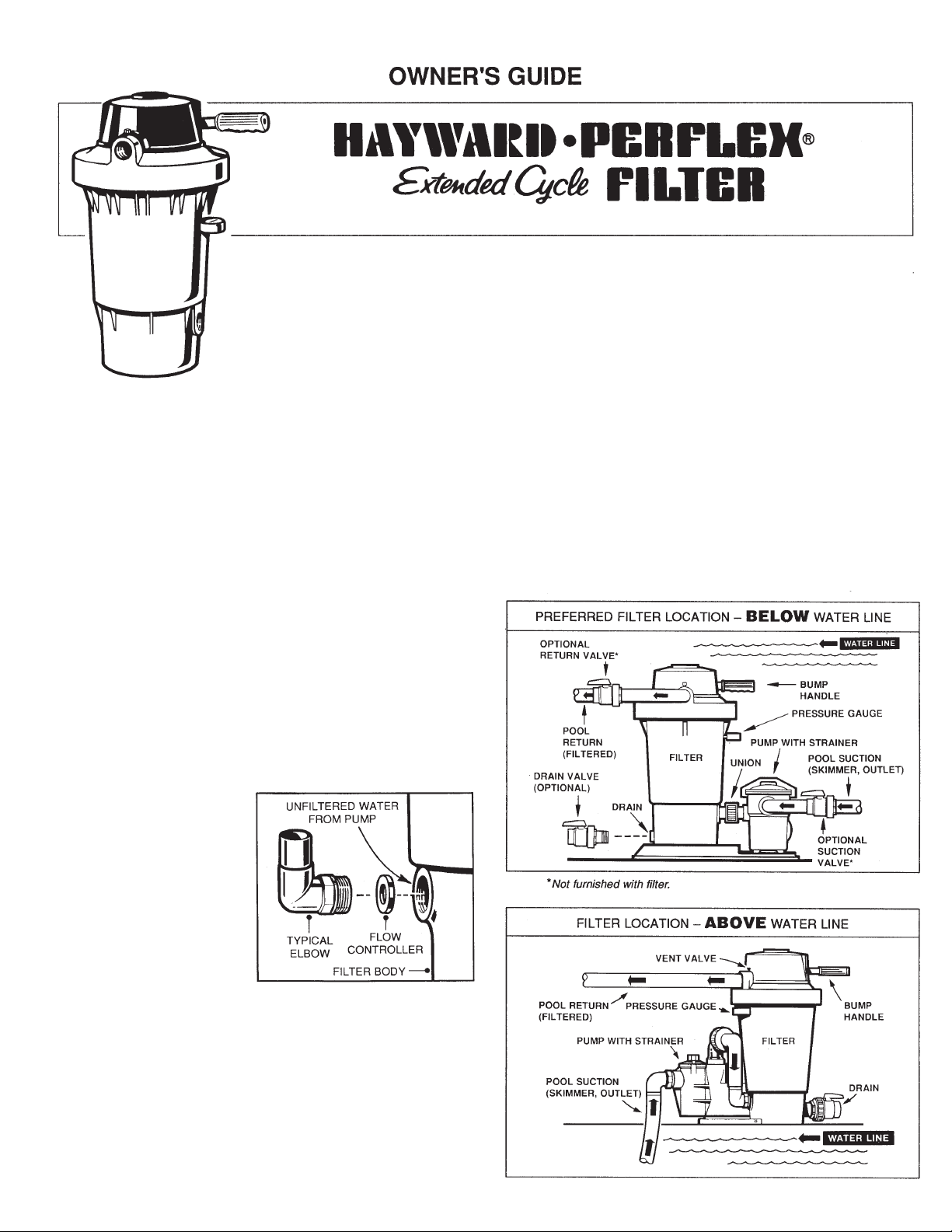
40 and 65 GPM (150-246 LPM). Install the flow
controller in the filter body as illustrated with an elbow adapter,
union connector, or adapter. The adapter both secures the
controller in its proper
position, and completes
the hydraulic balance of
the system.
FILTER LOCATION
Since plumbing fittings
offer a resistance to
water flow, locate the
filter as close to the
swimming pool as
practical. Keep the
number of fittings to a minimum. Select a well-drained area,
one that will not flood when it rains.
Set the filter on a
level
platform or base. Keep the filter
“BUMP” handle, drain outlet, and pressure gauge
accessible for convenient operation. There is an alternate
“BUMP” handle location on the other side of the filter out
let.
Instructions for changing the handle position are covered
later.
Position the filter so the tank can drain by gravity.
PLUMBING
Use 1-1/4” or 1-1/2” I.D. flexible plastic pipe, or hose, joined
with insert fittings and stainless steel clamps. If a rigid pipe
is used, be sure to provide unions for easy servicing.
Ball-style control valves are recommended.
All plumbing connections on the EC40 filter are 1-1/2” N.P.T.
When making connections to the filter, use plastic male-end
adapters. Apply three turns of Teflon tape or plastic pipe
sealant to the male threads.
IS40AB-98
1.
2.
3.
1.
2.
3.
MODEL EC40 SERIES
The Perflex Model EC40 is a high performance swimming pool filter with a filtration rating of 2,400 gallons
(9.1 KL) per hour. Manufactured from durable, corrosion-proof materials, it is designed for continuous
operation, for installation above or below the pool water line, for fresh or salt water swimming pools. The
EC40 filter uses diatomite filter powder (commonly called D.E.). D.E. is the most efficient dirt remover known.
It is normally fed into the system through the skimmer when the filter is initially started; then drained from the
filter when its dirt holding capacity has been reached. Through Perflex’s exclusive “BUMP” action, the D.E.
is periodically regenerated and the filter cycle extended without changing the powder. When the filter
powder is totally used, the “BUMP” action makes it possible to drain the used diatomite without backwashing
or dismantling the filter.
Page 2
SPECIFICATIONS
MODEL
NO.
EFFECTIVE
FILTRATION
AREA
DESIGN FLOW RATE
RESIDENTIAL PUBLIC
PRESSURE LOSS AT
DESIGN FLOW RATE
RESIDENTIAL PUBLIC
MAXIMUM
WORKING
PRESSURE
REQUIRED CLEARANCE
SIDE ABOVE
EC40 19 ft.21.8 m
2
38
GPM
144
LPM
38
GPM
144
LPM
3
PSI
0.2
BAR
3
PSI
0.2
BAR
50
PSI
3.45
BAR
12 inch 30 cm 18 inch
46 cm
NOTE: ANSI/NSPI-4 Article V, standard for above-ground and
on-ground pools, advises that components such as the
filtration system, pumps and heater be positioned so as to
prevent their being used as a means of access to the pool by
young children.
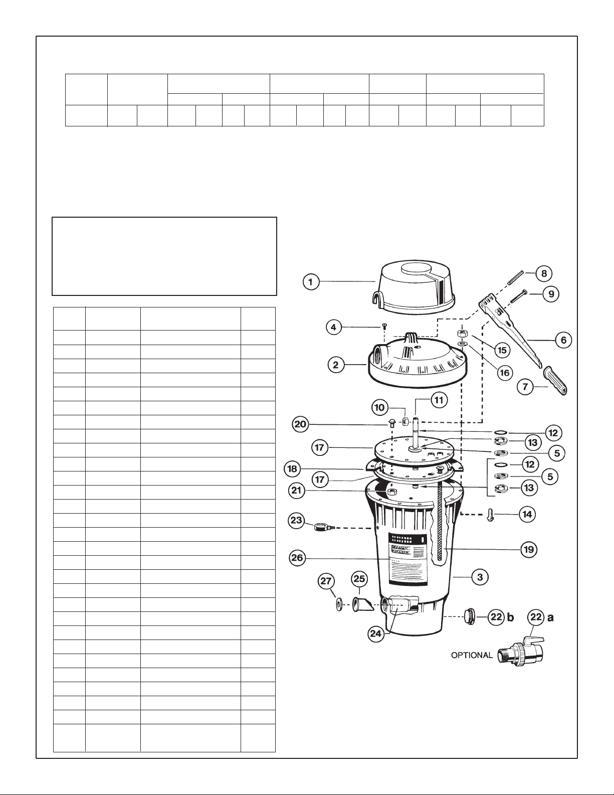
PARTS
MODEL EC40 SERIES FILTER
REF.
NO.
1
2
3
4
5
6
7
8
9
10
11
12
13
14
15
16
17
18
19
20
21
22a
22b
23
24
25
26
27
---
NO.
REQ’D.
1
1
1
1
2
1
1
1
1
1
1
2
2
12
12
12
2
1
72
12
12
1
1
1
1
1
1
1
1
PART NO.
EC1006
EC1033B
ECX10344
ECX1321A
ECX1011
ECX1040
ECX1037B
ECX100Z9
ECX4236
ECX4249
ECX1009
ECX9611246
ECX1014
ECX10271
ECX176855
ECX1077
ECX1004
ECX1003
ECX1031
SPX1500N1
SPX1500Y1
SP0723
SPX1022C
EC2708
ECX1005
ECX4077B
ECX1028
ECX1055
ECX1035
DESCRIPTION
Bump Mechanism Cover
Filter Head w/Vent Valve
Filter Body w/Flow Diffuser
Vent Valve w/O-Ring
Thrust Washer
Bump Handle Assembly
Bump Handle Grip
Pivot Pin
Shoulder Screw
Locknut
Bump Shaft
O-Ring
Retainer
Filter Head Screw
Filter Head Nut
Washer
Tube Sheet (Top or Bottom)
Diaphragm Gasket
Flex-Tube™ Assembly
Tube Sheet Screw
Tube Sheet Nut
1-1/2” Ball-Type Drain Valve
Plug w/Gasket
Pressure Gauge
Flow Diffuser
Check Valve
Decal — Operation
Flow Controller
Flex-Tube Nest (Incls. 5, 9,
10, 11, 14 thru 15)
Page 3

Screw the fitting into the thread hand tight; then, using a
wrench, tighten one more full turn. Additional tightening is
unnecessary and could result in broken or damaged fittings.
Refer to the diagrams for suggested valving.
Connect the pool suction plumbing between the skimmer,
pool outlet, etc., and the pump.
Install the pool return plumbing.
A drain plug, with gasket, is furnished with each filter and is
all that is needed for complete filter draining. If desired
however, drain piping may be extended from the filter by
using an appropriate length of 1 1/2” pipe. Piping must
slope away from the filter so the tank can drain by gravity.
DO NOT
use roll-flat type hose for drain piping.
BEFORE STARTING THE FILTER
Obtain a supply of operating chemicals, D.E., and a pool
test kit. Use only the swimming pool grades of D.E., such
as:
CELATOM . . . . . . . . . . . Eagle Pitcher Industries, Inc.
AQUA-CEL . . . . . . . . . . . Johns-Manville Products Corporation
DICALITE 4200 . . . . . . . Grefco, Inc.
WITCO . . . . . . . . . . . . . . Witco Corporation
Superchlorinate the pool water by adding unstabilized
granular or liquid chlorine. Stabilized forms of chlorine
are recommended for normal daily use after the initial
clean up of the water. Follow chemical manufacturer’s
recommendations for superchlorination and daily use.
STARTING THE FILTER
Close the filter drain and the vent valve. Caution: All suction
and discharge valves must be open when starting the
pump. Failure to do so could cause severe personal injury
and/or property damage.
Prime and start the pump following the manufacturer’s
instructions. Air trapped in the system will automatically vent to
the pool. When there is a steady flow of water returning to the
pool, the filter is ready for precoating.
DO NOT
operate the
filter for more than one minute without the precoat charge.
PRECOATING
Scoop 4 lbs. (1.8 kgs.) of diatomite into the system through the
skimmer as fast as the plumbing will take it. Note and record
the pressure gauge reading after the diatomite has been
added. This is the
“precoat pressure.”
FILTERING
Filtration starts as soon as the filter has been precoated. As
the filter removes dirt from the pool water, the accumulated dirt
causes a resistance to flow. As a result, the gauge pressure
will rise and flow will decrease. When the pressure rises 7-10
psi (.49-.70 Bar) above the precoat pressure, regenerate the
filter.
REGENERATION (Extending the Cycle)
Stop the pump. Move the bump handle down slowly, then up
briskly. Repeat 3 times. Restart the pump and filtration will
resume at near the original flow and pressure.
After each regeneration, and until the filter is cleaned, there
may be a slight increase in the starting pressure. This is the
result of dirt accumulating within the filter and is completely
normal.
CLEANING
Cleaning is recommended when the gauge pressure rises
more than 10 psi (.70 Bar) in less than a 24 hour period or
when cloudy water returns to the pool for more than 30
seconds after regeneration. To clean, first stop the pump, then
move the bump handle down slowly, then up briskly. Repeat 8
times. Open the filter drain and open the vent valve (Note: if
the filter is installed below the pool water line, close the suction
and return valves) and allow water and dirt to empty
completely.
After the filter has drained, and with the drain still open, run the
pump for a few seconds to flush out any dirt remaining in the
bottom of the filter. (Note: If the filter is installed below the pool
water line, opening the
suction
valve for a few seconds with the
pump off will adequately flush the unit.)
Close the filter drain and the vent valve. Open the suction and
return valves (when used). Start the pump and let the filter fill
with water and repeat the CLEANING procedure. This
completes the cleaning phase. The filter is now ready for
recharging. Proceed as in STARTING THE FILTER and
PRECOATING.
VACUUMING
Vacuuming can be performed directly into the filter whenever
needed. For fastest results, regenerate the filter before and
after each vacuuming operation.
TO CHANGE BUMP HANDLE POSITION
Remove the bump handle grip. Carefully pry the bump
cover from the head retaining groove and slide the cover off
the handle.
Using a drift (or 10 penny nail), tap the pivot pin out of the
filter head anchor point, freeing the end of the handle.
Rotate the bump handle to the alternate position and align
the handle and the head anchor holes. Tap the pivot pin in
place.
Reinstall the bump cover and grip.
PREVENTIVE MAINTENANCE
While Perflex filters are basically resistant to the difficulties
often encountered as a result of chemical build-up in swimming
pools, it is important to keep in mind that the mineral content in
a pool increases every day as a result of the chemicals added
and the normal water evaporation process. If the concentration
of minerals is allowed to get too high, the minerals will form
deposits on the Flex-Tubes inside the filter, and will eventually
result in shortened filter cycles. To guard against this, a yearly
chemical cleaning (soaking) of the Flex-Tube assembly is
suggested. Use commercially available 20% muriatic acid
added to water in 1 to 1 ratio; or use other commercial filter
element cleaner mixed according to the package instructions.
Use a plastic container and take extreme caution when
handling cleaning agents as they can be harmful to the eyes,
skin and clothing. After cleaning, thoroughly flush all affected
parts with cold water.
4.
5.
6.
7.
1.
2.
1.
2.
3.
4.
Page 4

WINTERIZING
In areas where sub-freezing temperatures can be expected,
the filter should be drained and removed from its operating
location and stored indoors. Prior to removal, cycle the filter as
described under CLEANING.
ALGAE CONTROL
Algae is a form of plant life which can vary in size from a few
thousandths of an inch to the size of a small tree. Of the many
forms of algae, those most frequently found in swimming pool
water are microscopic in size and green in color.
Algae readily grows in sunlight and can, under favorable
conditions, quickly overgrow a swimming pool turning it
completely green in just a few hours. On the other hand,
swimming pool water can be kept unfavorable to algae growth
simply by maintaining a chlorine level of at least 0.5 ppm in the
water at all times. The chlorine level should be checked at
least once a day using a suitable test kit.
If an algae condition develops and the pool water “blooms”
green, superchlorination of the pool will be necessary to clear
it. Add unstabilized granular chlorine, or liquid chlorine. Follow
SERVICE & REPAIRS
Consult your local authorized
Hayward-Perflex
dealer or
service center. No returns may be made directly to the factory
without the expressed written authorization of Hayward Pool
Products, Inc.
chemical manufacturer’s recommendation for superchlorination.
The algae will quickly become inactive and can then be
removed by the filter. Live algae, on the other hand, multiplies
so fast that the filter cannot keep up with its growth rate. In an
active algae situation, it may be necessary to regenerate the
Perflex filter as frequently as every 2 to 3 hours.
When correctly used, commercial algaecides are effective
against algae, though algaecides should be used in
conjunction with, and not as a substitute for, regular
chlorination or superchlorination.
Maintaining a chlorine level of at least 0.5 ppm in the pool water
at all times is the most effective way to prevent algae growth in
swimming pools.
POOL CHEMISTRY GUIDELINES
ACTION REQUIRED TO CORRECT POOL CHEMISTRY
TO RAISE
TO LOWER
SUGGESTED POOL CHEMISTRY LEVELS
pH
TOTAL ALKALINITY
CHLORINE (UNSTABILIZED)
CHLORINE (STABILIZED)
CHLORINE STABILIZER
(Cyanuric Acid)
7.2 to 7.6
100 to 130 ppm
0.3 to 1.0 ppm
1.0 to 3.0 ppm
40 to 70 ppm
Add Soda Ash
Add Sodium Bicarbonate
Add Chlorine Chemical
Add Chlorine Chemical
Add Stabilizer
Add Muriatic Acid or Sodium Bisulphate
Add Muriatic Acid
No action - chlorine will naturally dissipate
No action - chlorine will naturally dissipate
Dilution - partially drain & refill pool with water
that has not been treated with Cyanuric Acid.
©1998 Hayward Printed in U.S.A.
Rev. 11/98
 Loading...