

HAYWARD DE2420 User Manual
INSTALLATION, OPERATION, & PARTS
ISDE2423 Rev C
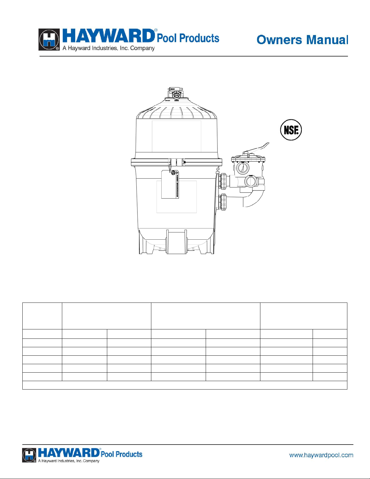
PRO-GRID VERTICAL DE FILTER SERIES
MODEL
FT2 M
DE2420 24 2.2 48 182 3.0 1.4
DE3620 36 3.4 72 273 4.5 2.0
DE4820 48 4.5 96 363 6.0 2.7
DE6020 60 5.6 120 454 7.5 3.4
DE7220 72 6.7 144 545 9.0 4.0
EFFECTIVE FILTRATION
RATE
2
GPM LPM LBS KGS
MAXIMUM WORKING PRESSURE FOR ALL MODELS 50 PSI (3.45 BAR)
DESIGN FLOW RATE
RECOMMENDED AMOUNT
OF D.E.
ATTENTION INSTALLER: THIS MANUAL CONTAINS IMPORTANT INFORMATION
ON THE OPERATION, AND SAFE USE OF THIS EQUIPMENT.
THIS MANUAL IS INTENDED FOR THE END USER OF THIS PRODUCT
USE ONLY HAYWARD GENUINE REPLACEMENT PARTS
Page 2 of 12 Pro-GridTM VERTICAL D.E. SERIES FILTER ISDE2423 REV C
This is the safety-alert symbol. When you see this symbol on your equipment or in this manual, look for one of the
following signal words and be alert to the potential for personal injury or death.
WARNING Warns about hazards that could cause serious personal injury or death, and if ignored presents a
potential hazard.
CAUTION Warns about hazards that will or can cause minor or moderate personal injury and if ignored presents a
potential hazard. It can also make consumers aware of actions that are unpredictable and unsafe.
The NOTICE label indicates special instructions that are important but not related to hazards.
READ, UNDERSTAND, AND FOLLOW ALL SAFETY AND OPERATION
INSTRUCTIONS. FAILURE TO FOLLOW SAFETY AND OPERATION INSTRUCTIONS CAN RESULT
IN SEVERE PERSONAL INJURY OR DEATH.
CAUTION To reduce risk of injury, do not permit children to use or climb on this product. Closely
supervise children at all times. The ANSI/NSPI-4 Standard (above-ground and on-ground poo l s) advises that
components such as the filtration system, pumps, and heaters be positioned to prevent their being used as a
means of access to the pool by young children.
WARNING COMPONENT SEPARATION HAZARD
Pool and spa water circulation systems operate under hazardous pressure during start up, normal
operation, and possibly after pump shut off. Pressure in system can cause explosive component
separation of the upper filter body if safety and operation instructions are not followed. Severe
personal injury or death can result.
This product should be installed and serviced only by a qualified pool professional.
TO AVOID COMPONENT SEPARATION
• Follow all safety and operation instructions.
• Do not operate water circulation system if a system component is assembled improperly, damaged, missing, or not a
genuine Hayward component.
• Before performing maintenance on the water circulation system, verify all system and pump controls are in OFF position
and filter manual air relief valve is in the OPEN position.
• Use ONLY Hayward clamp system components: DEX2421JKIT clamp assembly, DEX2421J2 nut/bolt assembly, and a
DEX2422Z2 metal reinforced seal.
Non-Hayward components may fail in use and cause explosive separatio n.
• Never rely on hand tightening the clamp nut to the clamp bolt. Using a ¾” socket on a torque wrench, torque clamp nut
and clamp bolt to 150 inch-lbs.
• Before starting system pump, insure filter manual air relief valve body is in LOCK position in filter upper body.
• Before starting the system pump, verify that all system valves are set in a position to allow water from the filter to return
back to the pool.
• Before starting the system pump, the manual air relief valve must be in the OPEN position.
• When starting pump, do not stand over or near filter.
• If water leakage appears in the area of the filter tank clamp, immediately turn off all system circulation pumps and
electrical power. Do not return to the filter until all water flow has stopped. Reassemble the clamp system per the
instructions in this owner’s manual to stop the leak.
• Return to filter to close manual air relief valve only when a steady stream of water (Not air or air and water mix) is
discharged from the manual air relief valve.
• Do not change filter control valve position while system pump is running.
WARNING EXCESS PRESSURE HAZARD
Pressure testing of the pump and filter system in excess of the 50 PSI can cause explosive separation
of the components. Component separation can result in severe personal injury or death.
WARNING ELECTROCUTION HAZARD
High Voltage electricity is present in the pool and spa equipment. High voltage electricity can cause
shock and electrocution. Shock and electrocution can result in severe personal injury or death.
• All electrical wiring MUST be in conformance with applicable local codes, regulations and the
National Electrical Code (NEC).
• Before performing any service or maintenance on electrical equipment turn off all electrical power.
• Contact a licensed electrician or building inspector for information on local electrical codes for bonding requirements.
• Verify water discharge from the filter manual air relief valve is directed away from electrical devices.
• Do not locate pump controls over or near filter.
USE ONLY HAYWARD GENUINE REPLACEMENT PARTS
Page 3 of 12 Pro-GridTM VERTICAL D.E. SERIES FILTER ISDE2423 REV C
WARNING – SUCTION ENTRAPMENT HAZARD.
Suction in suction outlets and/or suction outlet covers that are, damaged, broken, cracked,
missing, or unsecured can cause severe injury and/or death due to the following entrapment
hazards:
Hair Entrapment- Hair can become entangled in suction outlet cover.
Limb Entrapment- A limb inserted into an opening of a suction outlet sump or suction outlet
cover that is damaged, broken, cracked, missing, or not securely attached can result in a
mechanical bind or swelling of the limb.
Body Suction Entrapment- A negative pressure applied to a large portion of the body or
limbs can result in an entrapment.
Evisceration/ Disembowelment Entrapment- A negative pressure applied directly to the
intestines through an unprotected suction outlet sump or suction outlet cover that is,
damaged, broken, cracked, missing, or unsecured can result in evisceration/
disembowelment entrapment.
Mechanical Entrapment- There is potential for jewelry, swimsuit, hair decorations, finger,
toe or knuckle to be caught in an opening of a suction outlet cover resulting in mechanical
entrapment.
TO REDUCE THE RISK OF ENTRAPMENT HAZARDS:
• A minimum of two functioning suction outlets per pump must be installed. Suction outlets
in the same plane (i.e. floor or wall), must be installed a minimum of three feet (3’)
[.94 meter] apart, as measured from near point to near point.
• Dual suction outlets shall be placed in such locations and distances to avoid “dual
blockage” by a user.
• Dual suction outlets shall not be located on seating areas or on the backrest for such
seating areas.
• The pool or spa circulation system shall be designed to comply with ANSI/APSP-7 2006.
• Suction outlet covers shall conform to ANSI/ASME A112.19.8
• Never use Pool or Spa if any suction outlet component (cover/grate) is damaged, broken,
cracked, missing, or not securely attached.
• Immediately replace damaged, broken, cracked, missing, or not securely attached suction
outlet components.
• The CPSP as well as the ICC International Residential Code Part IX, Appendix G, Section
AG106 specifies the installation of a safety vacuum release system conforming to ASME
A112.19.17, or an approved gravity drain system.
• Failure to remove pressure test plugs and/or plugs used in winterization of the pool/spa
from the suction outlets can result in an increased potential for suction entrapment.
• Failure to keep suction outlet components clear of debris, such as leaves, dirt, hair, paper
and other material can result in an increased potential for suction entrapment.
Suction outlet covers and grates have a finite life. They should be inspected frequently
and replaced within specified life.
USE ONLY HAYWARD GENUINE REPLACEMENT PARTS
Page 4 of 12 Pro-GridTM VERTICAL D.E. SERIES FILTER ISDE2423 REV C
q
GENERAL INFORMATION
Your Hayward Pro-GridTM Vertical Grid D.E. Filter combines superior water filtration with ease of operation and totally
corrosion-free construction. It uses diatomaceous earth (D.E.), which is the most efficient dirt remover and filter medium
known.
The D.E., which is usually fed through the skimmer at initial start-up, uniformly coats the curved vertical filter elements
that are covered with a custom fitted monofilament polypropylene filter cloth. As pool water is pumped through the
control valve into the bottom of the filter tank, the D.E. surface, or coating, filters out even the minutest particles
resulting in clear, clean, sparkling water.
After a period of time, the accumulated dirt in the filter causes a resistance to flow, the pressure rises, and flow
diminishes. This means the dirt holding capacity of the D.E. has been reached, and it is time to clean (backwash) your
filter. With the control valve in the back wash position, the water is automatically reversed through the filter, flushing
trapped dirt, debris and D.E. out the waste line. Once the filter is backwashed (cleaned) of D.E. and dirt, the control
valve is manually re-sequenced to filter position and a fresh charge of D.E. is added to resume normal filtering.
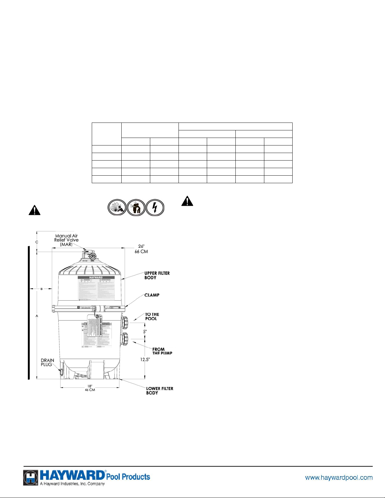
DE2420 32.0 81 18 46 15 38
DE3620 34.1 87 18 46 16 41
DE4820 40.1 102 18 46 18 46
DE6020 46.1 107 18 46 22 56
DE7220 52.0 132 18 46 25 63
A
IN CM IN CM IN CM
REQUIRED CLEARANCE
“B” SIDE “C” ABOVE
INSTALLATION
This product should be installed and serviced only by a
WARNING
ualified professional.
Only simple tools (screwdriver and wrenches), plus pipe sealant
for plastic adapters, are required to install and/or service the
filter.
1. The filter system should be installed on a level concrete slab
or other rigid base. Select a well drained and vented area,
one that does not flood when it rains. Position the filter so
that the piping connections, and winter drain are convenient
and accessible for operation, service, maintenance and
winterizing.
2. Position filter so the filter will drain by gravity.
3. If practical, place pump and filter in the shade to shield it
from continuous, direct heat from the sun.
4. Assemble appropriate Filter Control valve (See Page 10 for
selection) to filter. Lubricate the O-ring first (we recommend
using Jack’s 327 Lubricant). Align the two (2) valve pipe
connections, with O-rings in place, with the two openings in
the side of the filter tank and press in firmly. Secure the
assembly to the tank connections with the two bulkhead lock
nuts. Do not over-tighten.
5. Connect the pool suction plumbing between the skimmer,
pool outlet and the pump.
6. Install the pool return plumbing.
7. If pressure gauge is not installed, apply Teflon tape to the
gauge threads and carefully screw the gauge into the gauge
adapter assembly.
8. Do not locate pump controls over or near filter.
9. Verify water discharge from the filter manual air relief valve is
directed away from electrical devices
USE ONLY HAYWARD GENUINE REPLACEMENT PARTS
 Loading...