

Hayward ColorLogic LKCUS1100, ColorLogic LKCUB1100 Owner's Manual
USE ONLY HAYWARD GENUINE REPLACEMENT PARTS
USE ONLY HAYWARD GENUINE REPLACEMENT PARTS
IMPORTANT SAFETY
INSTRUCTIONS
WARNING – Before installing or servicing this electrical equipment, turn power OFF at the circuit
breaker.
READ AND FOLLOW ALL
INSTRUCTIONS
WARNING – Read and follow all instructions in this
owner’s manual. Failure to follow instructions can
cause severe injury and/or death.
WARNING – This product should be installed and
serviced only by a qualied professional.
CAUTION – All electrical wiring MUST be in conformance with all applicable local codes, regulations, and the National Electrical Code (NEC).
ATTENTION INSTALLER – THIS MANUAL CONTAINS
IMPORTANT INFORMATION ABOUT THE INSTALLATION, OPERATION, AND SAFE USE OF THIS PRODUCT THAT MUST BE FURNISHED TO THE END USER
OF THIS PRODUCT. FAILURE TO READ AND FOLLOW
ALL INSTRUCTIONS COULD RESULT IN SERIOUS INJURY.
WARNING – Risk of Electric Shock. Hazardous voltage can shock, burn, and cause death or serious
property damage. To reduce the risk of electric
shock, do NOT use an extension cord to connect
unit to electric supply.
WARNING – To reduce the risk of electric shock, the
ground wire must be connected to the grounding
means provided in the electric supply panel with a
conductor equivalent in size to the circuit conductors supplying this equipment.
WARNING – Do not submerge the ColorLogic Light
Controller.
CAUTION – Do not connect two or more ColorLogic
Light Controllers together.
WARNING - To reduce the risk of injury, do not permit
children to use this product unless they are closely
supervised at all times.
WARNING - For indoor use only. This unit is not
intended for outdoor use unless mounted in a suitable UL rated weatherproof outlet box and cover.
SAVE THESE INSTRUCTIONS
Introduction
The Hayward Light Controller offers a dedicated solution
for controlling your ColorLogic LED pool and spa lights
from a convenient remote location. It’s designed to install
into a standard wall electrical box and is wired to the high
voltage side of the ColorLogic light’s transformer. Once
installed, the Light Controller can be used to fully control
your pool and spa lights. Turn lights on/off and change to
fixed colors or shows using the Light Controller’s rotary
knob and front buttons.
Specifications
CSA enclosure type: Type 2, ENCL 2, or equivalent
Indoor electrical box: UL recognized single or multi gang
with minimum 14.0 in
3
volume
Outdoor electrical box:
UL recognized single or multi gang
with minimum 18.0 in
3
volume
Compatibility
The Light Controller is compatible with the following
ColorLogic Low Voltage LED lights:
• Universal ColorLogic Pool LED Light
• Universal ColorLogic Spa LED Light
•
ColorLogic 320, 160
, 80 and 40 LED Lights
Total allowable light wattage for the Light Controller is 300
watts. A combination of various lights can be used but
total wattage must not exceed 300 watts. Refer to your
ColorLogic light’s power consumption when determining
how many lights to use with the Light Controller. An
example of combinations are shown below:
• 3 Pool Lights
• 2 Pool Lights and 1 Spa and/or Accent Light
• 1 Pool Light and 4 Spa and/or Accent Lights
• 6 Spa Lights
• 6 Accent Lights (320 model)
• Any combination that does not exceed 300 watts
IMPORTANT: Add the individual wattage for each light
and do not exceed 300 watts.
Before you Begin
Set your ColorLogic lights to “UCL mode” BEFORE installing
the Light Controller (refer to your light’s manual). If not in
“UCL mode”, the ColorLogic lights will not operate properly
after the Light Controller is installed.
NOTE: The Light Controller requires a Neutral connection
to operate. If retrofitting into an existing installation, make
sure that the electrical box contains a Neutral connection.
Installation
Mounting Location
The Light Controller installs into a standard electrical
outlet box. When determining a suitable location, consider
that wiring from the Light Controller must connect to the
primary side of the light’s low voltage transformer.
Note that the Light Controller is designed for indoor
use but can be mounted outdoors if a suitable UL rated
weatherproof outlet box and cover are used.
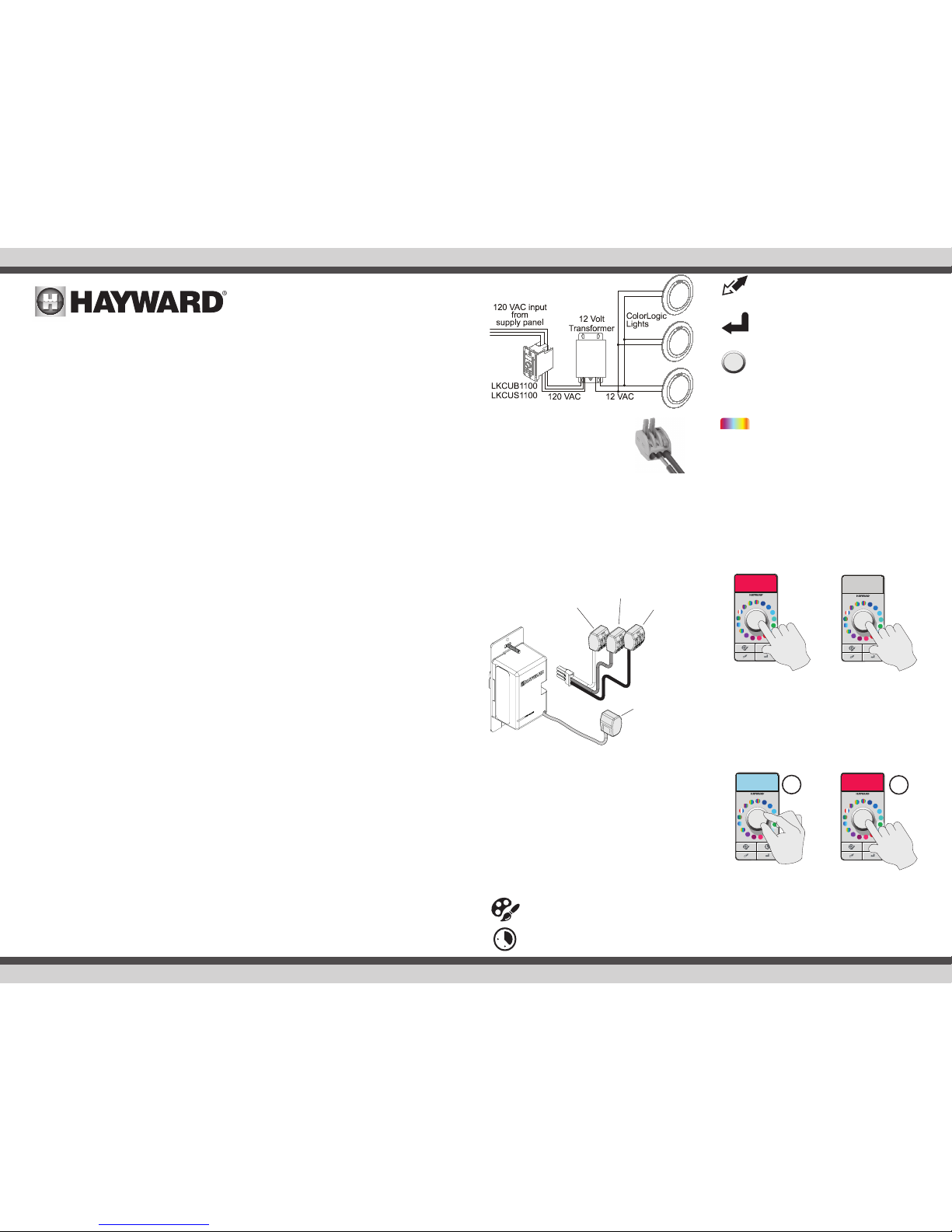
Wiring
Neutral in
from supply
(required)
&
Neutral out
to transformer
Line out
to transformer
black
Line in
from supply
red
white
green
Ground in
from supply
&
Ground out
to transformer
RESYNC - use this button to resume connection with the ColorLogic lights if communication is interrupted.
ENTER - use this button to confirm a selection
while in SCHEDULE mode.
CENTER KNOB - To turn the lights on, briefly
push on the CENTER KNOB. To turn the lights
off, push in and hold for 3 seconds. To change
a show or color, rotate the CENTER KNOB to
the desired show/color and push the CENTER
KNOB briefly to save.
PREVIEW WINDOW - this is the LCD display
above the CENTER KNOB. The PREVIEW
WINDOW shows the color or light show that
has been selected via the CENTER KNOB. The
PREVIEW WINDOW will remain on 5 minutes
after the last user input.
Off & On
Turn the lights on by briefly pushing in the CENTER KNOB.
To turn off, push on the CENTER KNOB and hold for 3
seconds. The Light Controller may indicate that it’s “busy”
by cycling through all LEDs in a circular pattern. This is
normal operation and occurs whenever the Light Controller
is busy processing a request. Let the Light Controller come
out of this state before continuing.
Select Color or Show
To select a specific color or show, rotate the CENTER
KNOB to the desired selection. The PREVIEW WINDOW
will display the desired color/show. Briefly push CENTER
KNOB to save. The lights will change to the new selection.
If you try to save the same color or show that is currently
selected, the Light Controller will indicate that no change
will occur by blinking LED 1 (see LED Indicator Codes) and
remain in Show/Color mode.
To turn OFF, hold
the CENTER
KNOB for 3
seconds
To Turn ON,
briefly push the
CENTER KNOB
Rotate CENTER
KNOB to select
desired color or
show
Briefly push the
CENTER KNOB to
save
Lever action terminal blocks are included to aid in installation. Move
levers to the fully open position when
inserting wires. Close the levers to
lock the wires in place.
Connect the Light Controller’s green wire to ground using
a lever action terminal block that is supplied. The Light
Controller comes with a plug-in wiring harness for easy
installation and removal. All wiring connections should
be made directly to the harness using the additional lever
action terminal blocks. After wiring is complete, the harness
can be plugged into the back of the Light Controller. It
can then be secured into the electrical box. Refer to the
following diagram for wiring connections.
Operation
After wiring is complete, turn on power at the circuit
breaker that is connected to Light Controller. The Light
Controller will initiate communication with the ColorLogic
lights. This may take a minute or two as the lights will
cycle between colors and finally default to the Voodoo
Lounge light show. The Light Controller will indicate this
in the PREVIEW WINDOW.
Refer to the following information for operation and control
of your ColorLogic lights.
Onboard pushbuttons
For best results, press on the outside of pushbuttons.
SHOW/COLOR -this is the default mode and
is used to control light shows and colors.
SCHEDULE - this is a programming mode and
is used to set a countdown timer or schedule.
1
2
USE ONLY HAYWARD GENUINE REPLACEMENT PARTS
USE ONLY HAYWARD GENUINE REPLACEMENT PARTS
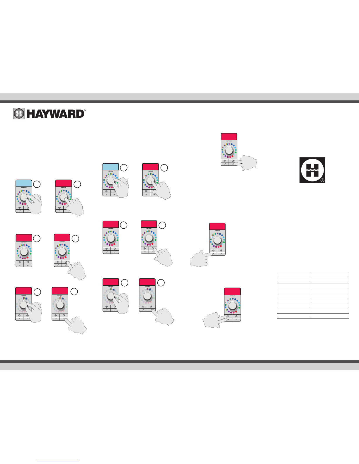
Set Countdown Timer
The Light Controller offers a countdown timer function for
your pool and spa light(s). When activated, the lights will
stay on for a predetermined amount of time set by the
user, then turn off automatically. To set the countdown
timer follow the procedure below. When selecting the
duration, note that each lit LED represents 1 hour. The
total number of LEDs that are lit = the total duration in
hours. The lights will automatically turn off at the end of
the countdown duration.
The example below shows that the lights will stay on for
2 hours and then automatically shut off.
The Light Controller will indicate that a new countdown
timer has been set by blinking LED 5 (see LED Indicator
Codes) and then revert to Show/Color mode.
Set Recurring Schedule
The procedure to set a schedule is identical to setting a
countdown timer, except that the ENTER button is held for
3 seconds at the end of the procedure. Once set, the lights
will turn on daily at the same time each day and stay on for
the duration that was selected. If the lights are already on,
they will change to the scheduled color or show.
The example below shows that the lights will turn on
automatically every day (beginning immediately after the
schedule is saved) and shut off after 2 hours.
The Light Controller will indicate that a new schedule has
been set by blinking LED 4 (see LED Indicator Codes) and
then revert to Show/Color mode.
Cancelling a Countdown Timer or Schedule
The procedure for cancelling a countdown timer or a
schedule is identical. Push and hold both the SCHEDULE
button and the ENTER button for 3 seconds. The Light
Controller will cancel the existing settings and will revert
to Show/Color mode.
The Light Controller will indicate that a countdown timer
or schedule has been cancelled by blinking LED 6 (see
LED Indicator Codes).
Resync
Occasionally the Light Controller may have to be resynchronized with the lights due to a power interruption
or other type of communication error. In that case, press
and hold the Resync button for 3 seconds. The Light
Controller will initiate a re-synchronization process that
will re-establish communication with the pool/spa lights.
This may take up to 1 minute.
Factory Reset
To clear all previous settings, press the SHOW/COLOR and
RESYNC buttons and hold for 3 seconds.
The Light Controller will indicate a factory reset by blinking
LED 7 (see LED Indicator Codes).
Warranty and Other Languages
Refer to hayward.com for other languages and warranty
information.
ColorLogic Light Controller
Owner’s Manual
LKCUS1100
LKCUB1100
092582 RevA
Push the
SCHEDULE
button
Select the number
of hours (each lit
LED = 1 hour)
Push and hold the
ENTER button for 3
seconds to save
Push and hold the
SCHEDULE and
ENTER buttons for
3 seconds
Push and hold the
RESYNC button for
3 seconds
®
Briefly push
the ENTER
button to
save
Rotate CENTER
KNOB to select
desired color or
show
Briefly push the
CENTER KNOB to
save
1
2
LED Indicator Codes
The Light Controller can indicate certain conditions by
blinking the front LEDs. Refer to the following conditions
and their corresponding indicator codes (LED 1 is at the
12 o’clock position, LED 2 is the 1st LED after the 12
o’clock position, etc.).
Condition Indicator Code
Same Selection LED 1 blinking
Overload LED 2 blinking
Busy LED 3 blinking
Recurring Schedule LED 4 blinking
One Time Countdown LED 5 blinking
Timer Reset LED 6 blinking
Factory Reset LED 7 blinking
Processing Request All LEDs in a circular pattern
3
4
5 6
Wait until all
LEDs stop
blinking
Push the
SCHEDULE
button
Rotate CENTER
KNOB to select
desired color or
show
Briefly push the
CENTER KNOB to
save
1
2
3
4
Wait until all
LEDs stop
blinking
Select the number
of hours (each lit
LED = 1 hour)
5
6
Hayward Pool Products
620 Division Street, Elizabeth NJ 07207
Phone (908)-355-7995
www.hayward.com
 Loading...