

Hayward ColorLogic 160, ColorLogic 320, CrystaLogic 160, CrystaLogic 320 Owner's Manual
160 & 320
ColorLogic
1.5” LED Lights
LED Light Fixtures
Owner’s Manual
092532 RevF
®
and CrystaLogic
TM
\
620 Division Street, Elizabeth NJ 07207
Contents
Safety Instructions..................................1
Introduction............................................2
Installation..............................................3
Operation...............................................9
Troubleshooting....................................11
Warranty................................................12
LACUS11xxx, LYCUS11xxx
LACUN11xxx, LYCUN11xxx
LAWUS11xxx, LYWUS11xxx
Hayward Pool Products
Phone (908)-355-7995
www.hayward.com
USE ONLY HAYWARD GENUINE REPLACEMENT PARTS

IMPORTANT SAFETY INSTRUCTIONS
SAFETY WARNING: Do not open. Light has no user serviceable parts inside. Improper installation
may result in death or serious injury to bathers or service personnel or others by way of electric
shock. Disconnect electrical power before installing or servicing this equipment. Read and follow all
instructions. This product to be installed by qualified personnel only.
INSTALLATION DEPTH REQUIREMENT: Except when the fixture is installed in an area of the swimming pool that is not used for swimming and the lens is adequately guarded to keep any person
from contacting it, the fixture must be installed in a wall or on a floor of a pool, spa, or water feature
with the top of the lens opening not less than 4 in. and no more than 72 in. below the normal water
level of the pool.
Model Input (Volts, Amps, Watts) Equivalent Brightness Lumens
LAC, LAW 14 VAC 60 Hz, 23 W 100W 1100
LYC, LYW 14 VAC 60 Hz, 13 W 60W 600
IMPORTANT WIRING CHECKLIST
Do not skip any steps in this or any section of the manual.
The above safety warnings and the complete installation instructions in this manual have
been read and followed.
A SAFETY LISTED POOL/SPA ISOLATION TRANSFORMER HAS BEEN USED TO SUPPLY
14 VOLTS TO THE FIXTURE.
The transformer output wiring HAS NOT been tied or shorted to ground.
The cord length has not been extended beyond the guidelines in this manual.
The cord jacket is not damaged, cut or spliced except as noted below.
Extensions or splices to the cord are only made in a safety listed Pool / Spa junction box
or junction box transformer system.
The luminaire is firmly secured to the pool wall and cannot be removed without the use
of a tool.
The luminaire has been installed by qualified personnel in compliance with the National
Electrical Code (NEC) or Canadian Electric Code (CE Code) and any applicable local
codes and/or regulations.
Installed by: ______________________ of company ____________________________
Date: __________________
LEAVE THESE INSTRUCTIONS WITH PROPERTY OWNER
1
USE ONLY HAYWARD GENUINE REPLACEMENT PARTS

Introduction
Congratulations on your purchase of a Hayward® ColorLogic® or CrystaLogicTM 1.5” LED Light.
Your Hayward ColorLogic and CrystaLogic 1.5” LED underwater light has these special features:
1. Long-lasting LED’s (light-emitting diodes) which can last up to 10 times longer than current
incandescent or halogen pool and spa lights.
2. ColorLogic models have multi color capability without any color wheels or moving parts to wear
out.
3. In Universal ColorLogic mode, the ColorLogic 1.5” light allows you to select any one of 17 different programs, 10 fixed colors, and 7 color shows in stand-alone mode.
4. In Omni Direct mode (requires either an OmniHub or OmniLogic pool controller), the LYCUS11xxx and LACUS11xxx lights offer 27 different programs; 20 fixed colors and 7 color shows
with full control over speed and brightness.
5. When networked with a Hayward Pro Logic® pool/spa controller (requires AQL-COLOR-MODHV),
LACUN11xxx and LYCUN11xxx light models are capable of 11 shows, 101 fixed light colors and
offer custom speed, brightness and motion control.
6. Offers spectacular brilliant light with low power consumption. Uses up to 86% less energy than
a typical incandescent pool light.
The 12 volt Hayward ColorLogic and CrystaLogic 1.5” LED (light-emitting diode) lighting fixtures
you have purchased are UL Listed and intended for use both in and out of water. Because of the all
plastic design with an impact resistant lens, these lights can be installed as little as 4 inches (10cm)
from below the normal water level of the pool or spa to the top of the lens. It can also be installed
upward facing on a floor without a rock guard for pools, spas, lighting ponds, fountains, or water falls.
Refer below for specific information about your 1.5” LED light model.
160 Models
LYWUS11xxx - white only, 100% brightness only
LYCUS11xxx - 100% brightness only
LYCUN11xxx - 100% brightness only, network support
320 Models
LAWUS11xxx - white only, selectable 50% or 100% brightness
LACUS11xxx - selectable 50% or 100% brightness
LACUN11xxx - selectable 50% or 100% brightness, network support
xxx - length of power cord
Installation
If replacing an existing light, remove power to the light at the panel before starting this installation.
Installation must be performed in accordance with Local and NEC codes.
Cord Length and Minimum Required Voltage
When installing ColorLogic/CrystaLogic 1.5” LED low voltage lights, the length of the cord has an
effect on performance. To prevent performance problems, verify the transformer is providing the
minimum required voltage according to the table below. To check this voltage, measure the voltage
2
USE ONLY HAYWARD GENUINE REPLACEMENT PARTS

at the transformer while the light is “on” and operating in “white” mode. In some cases, a voltage
Pool wall surface
4” min.
(top of lens)
4” min.
9” min.
11” min.
8” min.
Water line
to
12 VAC
Transformer
48”min.
1.5” PVC Conduit
1”Conduit
INSIDE POOL
use Hayward SP0536,
SP0537, SP0538 wall fittings
for LYWUS11xxx, LAWUS11xxx, LACUS11xxx & LYCUS11xxx models
for LACUN11xxx & LYCUN11xxx models
long sweep only
greater than 12 volts is required due to a long cord run. Some transformers provide higher voltage
taps for this purpose; check your transformer manufacturer’s installation instructions for details.
When using Hayward or other transformers that offer a 14v option, we suggest that you always use
the 14 volt tap.
Product
12v
Accent Light
Total Cord Length
from Transformer
to Light
30 ft
50 ft
100 ft - 150 ft
Minimum Required
Voltage at
Transformer
12 - 14 volts
13 - 14 volts
14 volts
Installation Overview
Refer to the diagram below of an overview of the ColorLogic/CrystaLogic 1.5” LED light installation.
Be sure to read all of the following sections before installation.
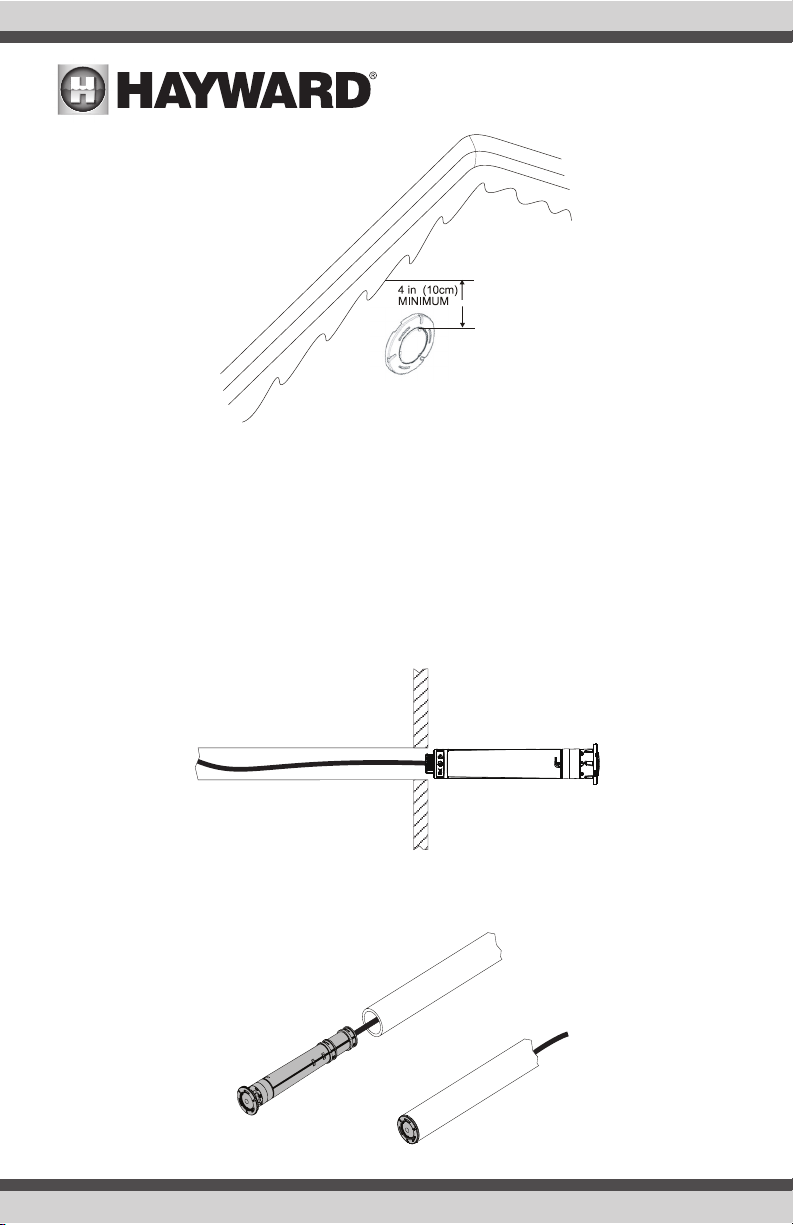
Installation Location
When installed in water, the ColorLogic or CrystaLogic 1.5” LED light must be installed in a wall or
on a floor of the pool or spa with the top of the lens not less than 4 inches (10 cm) below the normal
water level of the pool except when the fixture is installed in an area of the swimming pool that is not
used for swimming. Select a location for the light fixture(s) that will give optimum light dispersion for
the pool or spa design. Be sure to consider the direction of emitted light and take care not to point
lights directly at the house or outdoor living spaces.
3
USE ONLY HAYWARD GENUINE REPLACEMENT PARTS
PVC Conduit Run
INSIDE POOL
Install PVC from the desired installation location of the light, back to the transformer. For ease in
pulling the ColorLogic/CrystaLogic’s cable, use long sweeps only (no more than 3), no 90º elbows.
Finish the run before installing the light. Do not attempt to glue PVC or fittings while routing the cable.
Install the LED Light into PVC conduit
With the PVC conduit secure in the pool wall, follow these steps to secure the light:
1) Run the ColorLogic/CrystaLogic 1.5” LED light cord through the conduit to the transformer or
junction box location.
2) Insert the ColorLogic/CrystaLogic 1.5” LED light fully into the conduit as shown. IMPORTANT:
Do not use silicone or any other type of sealant.
USE ONLY HAYWARD GENUINE REPLACEMENT PARTS
4
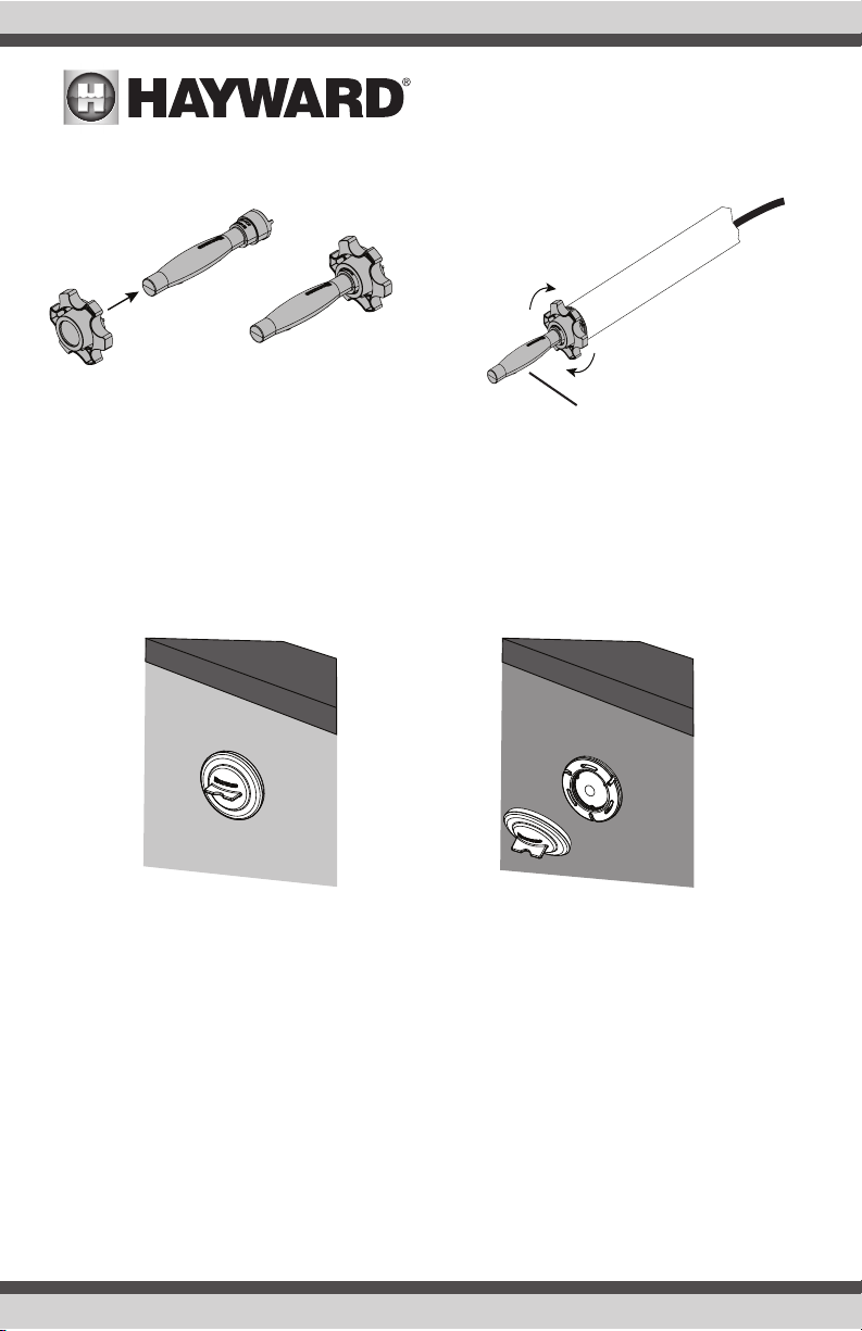
3) Assemble the included tool shown below. After assembly, insert the tool’s tabs into the light
face and handtighten until snug. Do not overtighen.
Hold handle steady while
rotating knob until snug
Plaster
Install the plaster shield onto the face of the ColorLogic/CrystaLogic 1.5” LED light before plastering
the pool walls. The shield is used to prevent gunite/plaster from coming in contact with the light face
and lens. Do not plaster over the light shield. Remove the shield when gunite/plaster has fully cured.
Install shield before plaster
Remove after plaster has cured
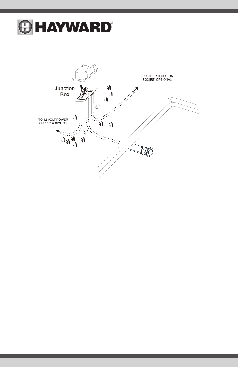
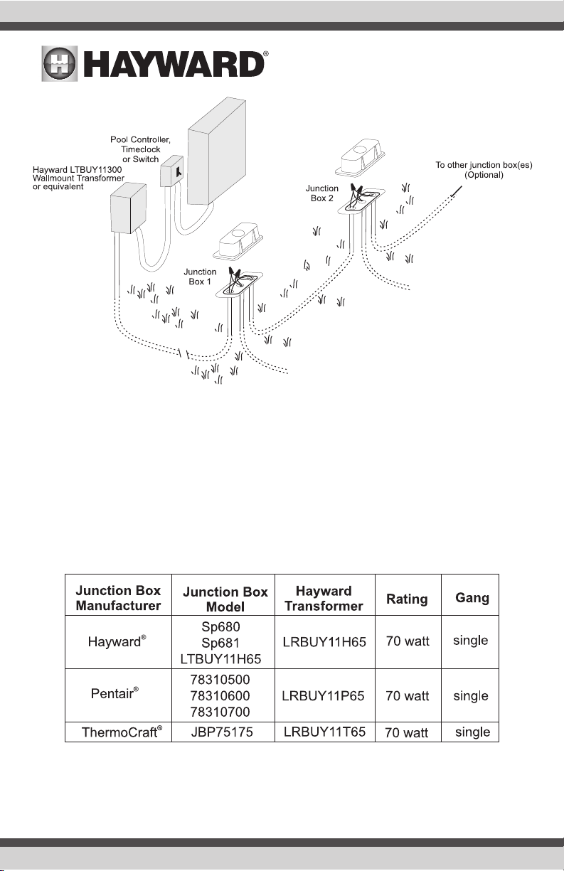
Install Junction Box or Junction Box Transformer
When using a wallmount low voltage transformer, a junction box should be installed to make the connection to the pool/spa light. If using more than one light, an adequate amount of single or double
outlet junction boxes will be required. Alternatively, Hayward low voltage junction box transformer
kits (LTBUY11H65) can be used when in-line transformers are desired. Refer to page 8 for more
information.
Junction boxes must be installed not less than 48 inches (1.22 m) from the edge of the pool or spa.
Run conduit from the mounting location up to the junction box such that the junction box is not less
5
USE ONLY HAYWARD GENUINE REPLACEMENT PARTS
than 8 inches (20 cm) above the maximum pool or spa water level, or not less than 4 inches (10 cm)
above the ground, whichever is greater. Additional conduit should be run from the junction box to the
power supply, switch panel, pool/spa controller, etc.
Install Wiring using a Wallmount Transformer
A suitable transformer must be installed which is agency listed for low-voltage swimming pool and
spa lights (Hayward LTBUY11300, Intermatic® model PX100/PX300, or equivalent). The transformer
must be rated at or above the total wattage used by all attached light fixtures. Up to 6 ColorLogic/
CrystaLogic 1.5” LED lights can be connected to a single Hayward LTBUY11300 transformer at the
14V tap.
Run conduit from the junction box to the low voltage transformer, pool/spa controller, or switch box.
Snake 2 wires through the conduit from the junction box to the power supply. If multiple lights are
being installed, run additional conduit/wires from the junction box to the additional junction box(es).
When wiring multiple lights to the same 12 volt source, do not exceed the transformers’s total rated
wattage. Refer to the manufacturer’s specifications and instructions for run length and wiring size.
Use wire nuts to connect the field-installed wiring to the light fixture cord in the junction box.
6
USE ONLY HAYWARD GENUINE REPLACEMENT PARTS
Install Wiring using a Hayward Junction Box Transformer
To Hayward
1.5” LED Light
To Hayward
1.5” LED Light
Hayward offers pool/spa light transformers designed to fit into various manufacturer’s junction boxes.
Refer to the table below to determine which model transformer will fit your type of junction box.
These transformers are designed to power up to two Hayward ColorLogic and/or CrystaLogic 1.5”
LED lights. If more than two lights are installed, multiple junction box transformers must be used.
Run conduit from the junction box transformer to the pool/spa controller or switch box. Snake 3
wires through the conduit. Connect the ground wires to the ground terminal connections inside the
junction box. Use wire nuts to connect the field-installed wiring to the 120V side of the transformer
and the 1.5” LED light cord to the low voltage side of the transformer. Refer to wiring diagram on
the following page.
7
USE ONLY HAYWARD GENUINE REPLACEMENT PARTS

1.5” LED Light
Yellow low
voltage leads
Ground
120V
Black
(hot)
120V
White
(neutral)
Bonding wire
if plastic conduit
To Hayward
Low voltage
to 1.5” LED light
120V from pool
controller or switch
For Network Control Only: Hayward LKBUN1000 Coupler
The Hayward LKBUN1000 is a coupler that is designed to be used with specific Hayward automation controls and an AQL-COLOR-MODHV Modem. Together, these components allow the user to
have complete network control over the installed ColorLogic light(s) using the Pro Logic Controller. When using network control, custom colors and
custom light shows can be programmed for each
or all lights. An LKBUN1000 is required for each
transformer in use and is designed to install into
the Hayward LTBUY11300 300 Watt and Hayward
Junction Box transformers. Refer to the LKBUN1000
installation manual for mounting and wiring instructions. See “Networking” on page 10.
USE ONLY HAYWARD GENUINE REPLACEMENT PARTS
8
 Loading...