

Page 1
ISCC200
Rev. D
____________________________________________________________________________________
OWNER’S MANUAL
INSTALLATION, OPERATION, & PARTS
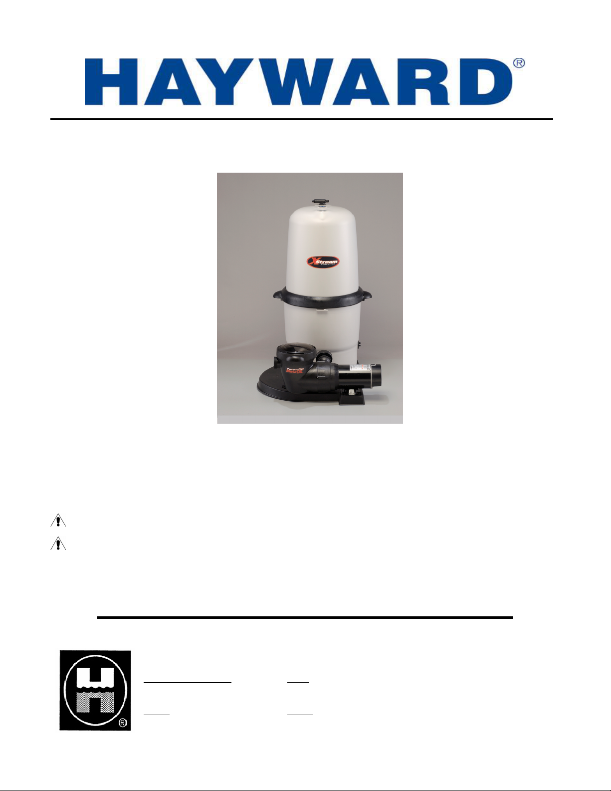
XStream™ Filtration Series
The Hayward® XStream™ Filtration Series is specifically designed for the demanding requirements of today’s above-ground
swimming pools. The advanced design reduces maintenance requirements while providing superior performance.
To prevent potential injury and to avoid unnecessary service calls, read this manual carefully and completely.
CAUTION – We highly recommend a qualified professional install and service this product.
WARNING – This manual contains important safety information that must be furnished to the end
user of this product. FAILURE TO READ AND FOLLOW ALL INSTRUCTIONS COULD RESULT IN
SERIOUS INJURY.
SAVE THIS INSTRUCTION MANUAL
HAYWARD POOL PRODUCTS, INC.
Corporate Headquarters: U.S.A:
620 Division Street 1 Hayward Industrial Drive 2935 Sidco Drive 2875 Pomona Blvd.
Elizabeth, NJ 07207 Clemmons, NC 27012 Nashville, TN 37204 Pomona, CA 91768
Canada: Europe:
2880 Plymouth Drive Parc Industriel de la plaine de l'Ain
01150 Saint Vulbas
France
Oakville, Ontario L6H 5R4 Allêe des Chênes
Page 2
XStream™ Filtration Series__________ _______________
(
)
PRODUCT REGISTRATION
DATE OF INSTALLATION ____________________
INITIAL PRESSURE GAUGE READING (CLEAN FILTER) _______________________
PUMP MODEL ________________ HORSEPOWER _______________________
FILTER MODEL ________________ SERIAL NUMBER _______________________
Retain For Your Records
IMPORTANT SAFETY INSTRUCTIONS
When installing and using this electrical equipment, basic safety precautions should always be
followed, including the following: Failure to follow instructions may result in injury.
READ AND FOLLOW ALL INSTRUCTIONS
IN THIS OWNER’S MANUAL AND ON
EQUIPMENT.
KEEP SAFETY LABELS IN GOOD CONDITION AND
REPLACE IF MISSING OR DAMAGED.
WARNING – To reduce risk of injury, do not permit children to use or climb on this
product. The ANSI/NSPI 4 Standard (above-ground and on-ground pools) advises that
components such as the filtration system, pumps, and heaters be positioned to prevent their being
used as a means of access to the pool by young children. Closely supervise children at all times.
CAUTION – The XStream™ Filtration Series is intended for use on permanently installed
above-ground swimming pools and may also be used with hot tubs and spas if so marked. Do
NOT use with storable pools. A permanently installed pool is constructed in or on the ground or
in a building such that it cannot be readily disassembled for storage. A storable pool is
constructed so that it is capable of being readily disassembled for storage and reassembled to its
original integrity.
Though this product is designed for outdoor use, it is strongly advised to protect the electrical
components from the weather. Select a well-drained area, one that will not flood when it rains. It
requires free circulation of air for cooling. Do not install in a damp or non-ventilated location.
Bond motor to pool structure. Use a solid copper conductor, size or larger. Run wire from
external bonding lug to reinforcing rod or mesh. Connect a No. 8 AWG (8.4 mm²) solid copper
bonding wire to the pressure wire connector provided on the motor housing and to all metal parts
of swimming pool, spa, or hot tub, and to all electrical equipment, metal piping or conduit within
5 ft. (1.5 m) of inside walls of swimming pool, spa, or hot tub. (In Canada use No. 6 AWG
bonding wire.)
Page 3
XStream™ Filtration Series __________ _____________________________________
NOTE: The National Electrical Code (NEC) permits use of a cord with a maximum 3 ft.
(1 m) length. If your pump is equipped with a cord complying with the NEC, the following three
(3) items apply.
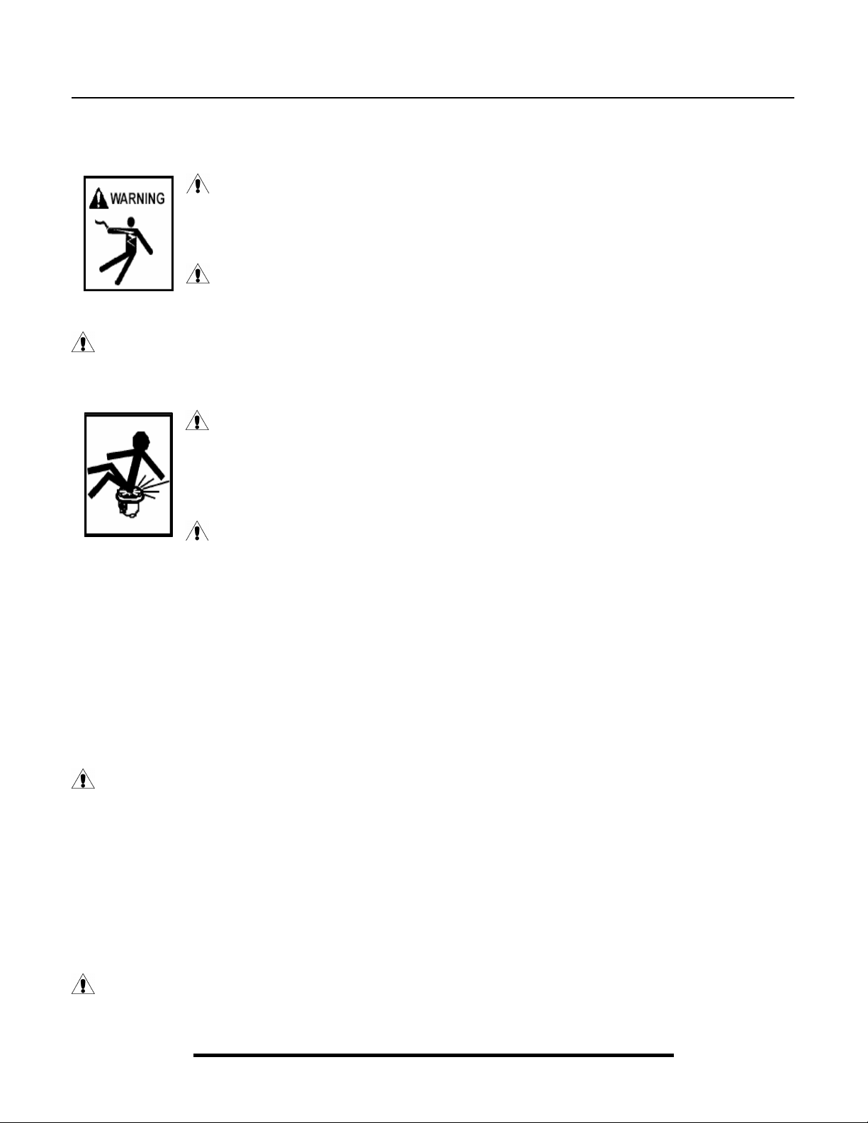
WARNING – Risk of Electric Shock. Connect only to a grounding
type receptacle protected by a Ground Fault Circuit Interrupter (GFCI). Contact a
qualified electrician if you cannot verify that the receptacle is protected by a
GFCI.
WARNING – To reduce the risk of electric shock replace damaged cord
immediately. Do NOT bury cord. Locate cord to minimize abuse from lawn
mowers, hedge trimmers and other equipment.
WARNING – To reduce the risk of electric shock, do NOT use an extension cord to
connect unit to electric supply. Provide a properly located outlet. Qualified personnel MUST do
all electrical wiring.
CAUTION – All suction and discharge valves MUST be OPEN when
starting the filter system. Failure to do so could result in severe personal injury
and/or property damage. All drains and suction covers MUST have properly
installed covers securely attached with the screws supplied with the covers. If
screws are lost, order replacement parts from your supplier.
DANGER – Suction Entrapment Hazard. Never use the pool or
spa if a drain cover is damaged, cracked, missing, or not securely attached. Suction in drains and
suction outlets can cause drowning, disembowelment, hair or body entrapment, severe injury, and
death. Disembowelment, entrapment, or drowning is possible when body parts or hair come in
contact with damaged, broken, cracked, missing, or unsecured drain covers and suction outlets.
Suction from pumps with only one drain or suction outlet can cause disembowelment,
entrapment, or drowning. Pumps for pools and spas require two (2) functioning suction outlets at
least three (3) feet apart, on two (2) walls or on the floor and one (1) wall of the pool or spa.
Installation of pump and suction outlets must be in compliance with all applicable local building
codes. Replace damaged, broken, cracked, missing, or unsecured drain covers and suction outlets
immediately.
WARNING – Hazardous Pressure. Pumps, filters, and other
equipment/components of a swimming pool filtration system operate under pressure. Incorrectly
installed and/or improperly tested filtration equipment and/or components may fail resulting in
injury and/or property damage. A qualified pool professional MUST conduct all pressure tests.
This product is intended for above-ground/on-ground swimming pool applications only. Do NOT
connect to a high-pressure system such as a municipal water main. To prevent explosion caused
by entrapped air in the filtration system use provided air relief valve to bleed air from the system.
Confirm that ALL filtration system component clamps, bolts, and covers have been tightened to
the manufacturer’s recommendations.
WARNING – Never operate or test the filtration system at more than 30 PSI.
SAVE THESE INSTRUCTIONS
Page 4

XStream™ Filtration Series _____________________________________
Product Specifications
XStream™ Filtration Components
Filter Type: Full-Flow Cartridge Element
Filter Tank: Injection-Molded PermaGlass XL™
Filter Element: Reinforced Polyester Element
Fastenings: Easy-Lok™ Ring Assembly
Mounting Base: Injection-Molded PermaGlass XL™
XStream™ Filtration Performance Data
Model No. CC1000 CC1500 CC2000
Effective Filtration Area 100 FT² 150 FT² 200 FT²
Design Flow Rate 80 GPM 100 GPM 120 GPM
Maximum Working Pressure 30 PSI 30 PSI 30 PSI
Required Clearance:
Side 18” 18” 18”
Above 24” 30” 36”
Replacement Hayward Cartridge CCX1000RE CCX1500RE CCX2000RE
Turnover
8 Hours 38,400 GAL 48,000 GAL 57,600 GAL
12 Hours 57,600 GAL 72,000 GAL 86,400 GAL
Page 5

XStream™ Filtration Series _________________________
General Information
Introduction
This manual contains information for the proper installation and operation of the Hayward
Series. All
this manual MUST be followed precisely.
XStream™ Filtration models are high performance, above-ground swimming pool filters. Instructions in
®
XStream™ Filtration
Product Features
Engineered for easy use with flexible or rigid plumbing.
Sleek, flush mounted pressure gauge.
Extra large dirt capacity.
Quick release, high capacity air relief valve.
Glass reinforced, non-corrosive Permaglass XL™ filter tank will provide years of trouble-free operation.
Easy-Lok™ ring design allows quick access to all internal components in a single turn.
Installation Instructions
Filter Location
Set the filter on firm, level ground. Select a well-drained
area, one that will not flood when it rains. Position the filter
so that it may drain by gravity. The tank should be
positioned for easy access to the internals, pressure gauge,
and air relief valve.
Plumbing
To facilitate servicing of the filter system and to allow for
indoor storage during the winter months, installing union connections at the suction and outlet ports is recommended.
Use Teflon tape to seal threaded connections on molded plastic components. All plastic fittings must be new or
thoroughly cleaned before use. NOTE: Do NOT use Plumber’s Pipe Dope as it may cause cracking of the plastic
components. When applying Teflon tape to plastic threads, wrap the entire threaded portion of the male fitting with
one to two layers of tape. Wind the tape clockwise as you face the open end of the fitting, beginning at the end of the
fitting.
The pump suction and outlet ports have molded-in thread stops. Do NOT attempt to force hose connector fitting past
this stop. It is only necessary to tighten fittings enough to prevent leakage. Tighten fitting by hand and then use a tool
to engage fitting an additional 1 ½ turns. Use care when using Teflon tape as friction is reduced considerably; do
NOT over-tighten fitting or you may cause damage. If leaks occur, remove connector, clean off old Teflon tape, rewrap with one to two additional layers of Teflon tape, and re-install connector. Use 1 ½” I.D. flexible plastic pipe
with hose adapter fittings and hose clamps. If rigid PVC is used, be sure to install Hayward SP1500UNPAK2 union
connectors for easy servicing.
All plumbing connections on the XStream™ Filter are 1 ½” N.P.T. When making connections, use plastic male-end
adapters. Apply three (3) turns of Teflon tape or plastic pipe sealant to the male threads. Screw the fitting into the
thread hand-tight; then using a wrench, tighten one more full turn, if necessary. (NOTE: Adapters have varying
tolerances and over-tightening with a wrench may only cause damage to the filter.) Ball type valves are recommended
where needed.
Connect the pool suction plumbing between the skimmer and the pump. Connect the pool return plumbing to the
OUTLET port at the bottom of the filter body.
A filter drain or plug is furnished with each filter and is all that is needed for complete filter draining. A manual air
relief valve is furnished to aid in the bleeding of unwanted air when starting or draining the filter.
Page 6

XStream™ Filtration Series _____________________________________
Start-Up & Operation
New Installation/Seasonal Start-Up
1. Close drain valve at the base of filter.
2. Secure and lock Easy-Lok™ ring.
3. Open air relief valve (Turn lever to left).
4. Open valves (Optional suction & return valves).
CAUTION – All suction and outlet valves MUST be OPEN before operating the filter
system. Failure to do so could cause severe personal injury and/or property damage.
5. Prime and start the pump per manufacturer’s instructions.
6. Once air has escaped the filter and a steady stream of water is flowing from the air relief valve, close the air
relief valve and note the pressure gauge reading.
Dis-Assembly & Assembly
Cleaning/Removing Cartridge Element
NOTE: An indication that the filter needs cleaning is when the pressure gauge rises 5-7 PSI above its normal
pressure.
1. Shut off the pump.
2. Close valves* (*optional: suction & return valves).
3. Open air relief valve.
4. Open drain plug (located at the base of the filter body).
5. Depress safety latches (located on the underside of the locking ring handles) and unscrew locking ring in a
counter-clockwise direction. Remove lid from filter body.
6. Lift out filter element and clean as instructed in “Preventative Maintenance” section of this manual.
Re-Installing Cartridge Element
1. Clean debris from bottom of filter tank.
2. Replace element evenly on the collector hub in bottom of the filter body.
3. Place lid evenly on filter body and turn Easy-Lok™ ring clockwise until the safety latches engage securely.
4. Close and secure drain plug (located at the base of filter body).
5. Proceed as in “Start-Up & Operation”.
Preventative Maintenance
Cleaning Cartridge Filter
NOTE: Clean the cartridge when filter canister pressure reaches 5-7 PSI above the initial system or new
cartridge starting pressure.
1. Remove the cartridge element from the filter housing following the directions in the “Cleaning/Removing
Cartridge Element” section above.
2. Pressure wash the cartridge element inside and out with the Hayward Jet-action Cleaning Wand (EC2024) or
a garden hose with a high-pressure nozzle. Work from top-down, holding the nozzle at a 45-degree angle.
Rinse until all dirt and debris are gone. Brush pleated surface areas and allow to dry.
Page 7

XStream™ Filtration Series_____________________________________________________________
Preventative Maintenance (cont.)
Cleaning Cartridge Filter (cont.)
To remove algae, suntan oil, and body oils:
Soak the cartridge element for at least one (1) hour (overnight is most effective) in: 1) a commercial filter
cleaner; OR 2) One (1) cup Tri-Sodium Phosphate (TSP) to five (5) gallons water; OR 3) One (1) cup
dishwasher detergent to five (5) gallons water.
Rinse cartridge element to remove oils and cleaning solution.
To remove calcium carbonate (residue from calcium hypochlorite), iron, or other mineral deposits:
Soak the cartridge element in a solution of one (1) part Muriatic Acid to twenty (20) parts water, until all
bubbling stops.
WARNING – Do NOT add water to acid.
WARNING – Do NOT mix chlorine and acid.
WARNING – Use a plastic container and
take extreme care – harmful to eyes, skin, and clothing. Always wear rubber gloves and
eye protection.
CAUTION – Failure to remove all oils and cleaning solution before acid soaking
will result in a permanent restriction of water flow and cause premature cartridge
failure.
3. Rinse the cartridge element clean and re-assemble filter housing.
Vacuuming
Vacuuming can be performed directly into the filter whenever needed. For fastest results, clean the filter before and
after each vacuuming. For heavy spring clean ups, we recommend using a Hayward SP0727 diverter valve to bypass
the filter and accelerate the clean up process. Consult your local Hayward dealer for a detailed explanation.
Winterization
In areas where sub-freezing temperatures can be expected, the filter should be drained and/or removed from its
operating location and stored indoors. Clean the cartridge element at the end of the pool season by using the Hayward
Jet-action Cleaning Wand (EC2024) or a garden hose with a high-pressure nozzle (See “Cleaning Cartridge Filter”
instructions in this manual).
Troubleshooting
Problem What to Look for Treatment
Damaged Cartridge
Element
Algae
Dirty, clogged, or abused element Dirt, debris, or tear in pleats or folds Clean or replace element
Oversized pump
- Produces
excessive
flow rates
and/or
pressures
Very dirty pool water
Flattened pleats or folds;
Embedded dirt or debris into the
filter material;
Breaking of internal core of the
element;
Breaking or splitting of the end
plates of the element
Algae buildup on the pool walls
Re-size pump
Frequent cartridge cleaning or
replacement;
Consult professional pool company
for pool chemistry instructions.
Page 8

Stream™ Filtration Series _____________________________________
X
Replacement Parts
Parts Diagram
Parts Listing
Ref.
No. Part No. Description Ctn. Qty. No. Req’d
1 ECX27091 Pressure Gauge 10 1
2 CCX1000L Threaded Adapter for Pressure Gauge 10 1
3 CCX1000V Air Relief Assembly with ‘O’ Ring 10 1
4 CCX1000D Lock Ring Assembly with 2 Safety Clips 1 1
5 CCX1000H Safety Clips for Lock Ring (Set of 2) 10 1
6a CCX1000C Filter Lid with Lock Ring, 100 sq. ft. 1 1
6b CCX1500C Filter Lid with Lock Ring, 150 sq. ft. 1 1
6c CCX2000C Filter Lid with Lock Ring, 200 sq. ft. 1 1
7 CCX1000N Adapter Nut 10 2
8a CCX1000RE Cartridge Element, 100 sq. ft. 1 1
8b CCX1500RE Cartridge Element, 150 sq. ft. 1 1
8c CCX2000RE Cartridge Element, 200 sq. ft. 1 1
9 CCX1000B Filter, Lower Body 1 1
10 SP1480BLK Self Aligning Union, Black 50 1
11a SP1592 1 HP Power-Flo Matrix Pump 1 1
11b SP1593 1-1/2 HP Power-Flo Matrix Pump 1 1
12 CCX1000A Base, Standard 1 1
13 SP1022CBLK Drain Plug with ‘O’ Ring 100 1
14 CCX1000G Body O-ring 2 1
15 SPX1500W Pressure Gauge ‘O’ Ring 10 1
16 CCX1000Z5 ‘O’ Rings for Gauge Adapter & Air Relief (Set of 2) 10 1
Page 9

XStream™ Filtration Series_____________________________________________________________
HAYWARD® LIMITED WARRANTY
This filter system was inspected before shipment from our plant. To original purchasers of this filter system,
Hayward Pool Products, Inc., 620 Division Street, Elizabeth, New Jersey, warrants its products free from defects in
materials and workmanship for a period of ONE (1) year from the date of purchase.
Parts which fail or become defective during the warranty period, except as a result of freezing, negligence, improper
installation, use, or care, shall be repaired or replaced, at our option, without charge, within 90 days of the receipt of
defective product, barring unforeseen delays.
Additionally, to original purchasers of this filter system, Hayward Pool Products, Inc., warrants its filter heads and
filter bodies made of Perma-Glass XL™ material to be free from defects in materials and workmanship for a period
of ONE (1) year from the date of purchase.
Filter heads and filter bodies which become defective during the warranty period, except as a result of freezing,
negligence, improper installation, use, or care, or as a result of use in association with an automatic valving system,
shall be repaired or replaced, at our option, without charge.
To obtain warranty replacements or repair, defective components or parts should be returned, transportation paid, to
the place of purchase, or to the nearest authorized Hayward service center. For further Hayward dealer or service
center information, contact Hayward customer service department. No returns may be made directly to the factory
without the express written authorization of Hayward Pool Products, Inc.
All other conditions and terms of the standard warranty apply.
Hayward shall not be responsible for cartage, removal and/or reinstallation labor or any other such costs incurred in
obtaining warranty replacements.
The Hayward Pool Products warranty does not apply to components manufactured by others. For such products, the
warranty established by the respective manufacturer will apply.
Some states do not allow a limitation on how long an implied warranty lasts, or the exclusion or limitation of
incidental or consequential damages, so the above limitation or exclusion may not apply to you.
This warranty gives you specific legal rights, and you may also have other rights, which vary from state to state.
Hayward Pool Products, Inc.
620 Division Street
*Supersedes all previous publications. Elizabeth, NJ 07207
▲Retain this Warranty Certificate (upper portion) in a safe and convenient location for your records.
▼DETACH HERE: Fill out bottom portion completely and mail within 10 days of purchase/installation.
------------------------------------------------------------------------------------------------------------
Mail to: Hayward Pool Products, Inc., 620 Division Street, Elizabeth, NJ 07207, Attn: Warranty Dept.
Warranty Registration Card
Name__________________________________________________ Years pool has been in service □ less than 1 □ 1-3 □ 3-5 □ 5-10
Address________________________________________________ Purchased from:
Company name________________________________________________
City______________________State_________ Zip ____________
Address_______________________________________________________
E-mail Address:_________________________________________
City___________________________State____________Zip_____________
Product Purchased_______________________________________
Product Serial No.________________________________________
Please send me more information on these other
□ New Installation □ Replacement products from Hayward:
Type of Pool:
□ In-ground □ Vinyl □ Fiberglass □ Gunite □ Above-ground □ Light □ Chlorinator □ Skimmer
Size of Pool______________________________________
□ Pump □ Filter □ Automatic Pool Cleaner
□ Heater
Page 10

 Loading...