

Hayward ProLogic, AquaLogic Troubleshooting Manual
ProLogic®/AquaLogic
CTSG-PL447a
Copyright 2016 Hayward Industries Inc.
Consumer Troubleshooting Guide

Safety Precautions
!
Warning
2
High Voltage Electrocution Hazard
Hazardous voltage can shock, burn, cause serious injury
and or death. To reduce the risk of electrocution and or
electric shock hazards:
• Only qualified technicians should remove the dead front
• Qualified technicians should: replace damaged
wiring immediately
• Qualified technicians should: Insure panel is properly
grounded and bonded

Table of Contents
How
ProLogic® Works
Pg.
4
How To:
Pg.
5-
15
Reset Average Salt & Adjust Chlorinator Output
6-
7
Adjust ORP Set Points & Adjust Heater Set Points
8-9 Clear Inspect Cell Message & Set a Pump Schedule
10-11
Change VSP Speed Settings & Clean the Turbo Cell
12-15
Troubleshooting:
Pg.
16-34
1. No Cell Power/Low
Volts
17
2. Chlorinator Off, High Salt/Amps
18-20
3. Chlorinator Off,
Cell Sensor Open
21 4. Freeze Protection Active:
In Error
22-23
5. Heater Not Firing
24-26
6. Auxiliary Equipment Inactive
27-28
7. Wireless Remote Not
Pairing to ProLogic
29-31
8.
Pump Error Codes & 9. Sense & Dispense Error Codes
32-33
10. Additional Sensor Error Codes
34
Additional Information:
Pg.
35-39
Cell Compatibility Chart & Salt
Addition Chart
36-37
Salt Addition
Chart & Chlorine Output
38-39
3
ProLogic: How It Works
• All ProLogic systems are salt chlorination ready
and can control 4-16 high voltage relays, 3-4
valve actuators and 1-2 heaters.
• These systems can manage: Hayward Variable
Speed Pumps, ColorLogic Lighting, Sense &
Dispense, AquaConnect Homenet, as well as a
wide variety of remotes.
• The panel features an 8 slot, 100amp subpanel.
• Equipment can be programmed to run off daily
schedules and/or based on manual commands.
Equipment such as heaters can be programed to
operate only on demand. Safety features suchas interlocks and freeze protection can help
protect pool pad equipment.
4
ProLogic®
How To:
Follow these steps ONLY if Salt Chlorination is Enabled. The Average Salt level needs to
be reset after initial start up, after a board replacement, following major pool
chemistry adjustments, and when a cell is replaced.
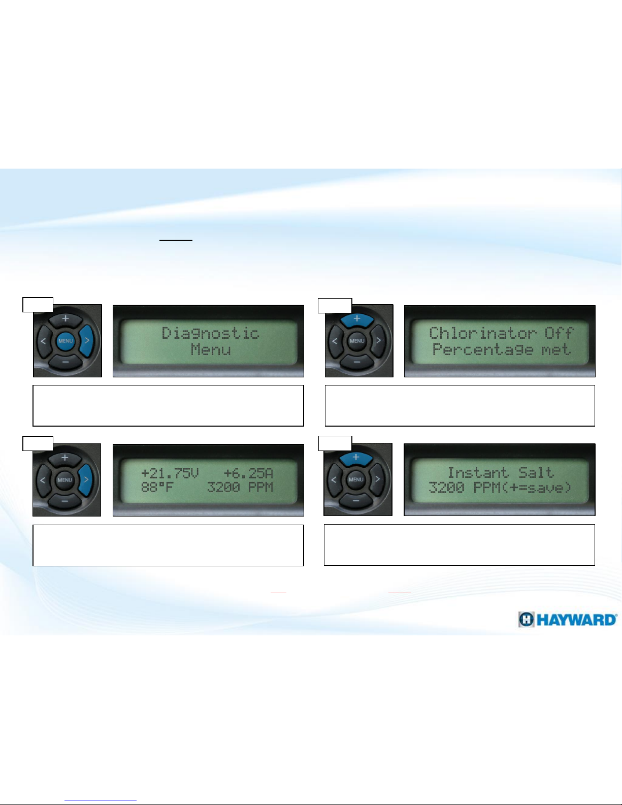
Press the (+) key to replace the existing average with this new
instant salt reading; this will start the average process over
again. Press the ‘Menu’ button to exit.
How To: Reset Average Salt
6
Step 3
Step 4
Step 1
The active salt readings (instant salt) appears in the ‘Diagnostic
Menu’. Press the ‘Menu’ button repeatedly, until the ‘Diagnostic
Menu’ appears. Then press (>) one time.
If all zeros or if ‘Chlorinator Off Percentage Met’, press (+) key.
IF, after a short countdown delay, the display does not revert to
zeros, refer to step 3.
NOTE: The main circulation pump MUST be ON and the chlorinator AND flow switch MUST have flow to
successfully complete this process.
Step 2
Above is an example of the updated instant salt reading in PPM.
If this instant salt reading varies from the average press the (>)
one time, then go to step 4.

Note: If the chlorine levels do not increase within 24 hours, test the water chemistry to determine the
current salt, stabilizer, phosphate, and nitrate levels.
For the second body of water, use the (+) or (-) key to adjust the
desired chlorinator output. Once complete, press the ‘Menu’
button to exit.
How To: Adjust Chlorinator Output
7
Follow these steps to adjust the Chlorinator Output Percentage ONLY if Salt
Chlorination is Enabled. NOTE: IF Sense & Dispense ‘ORP Auto Sensing’ is being used,
output must be adjusted under the ‘Chemistry Config. Wizard’; refer to next page.
Step 3
Step 4
Step 1
To display the settings, press the ‘Menu’ key until
‘Settings Menu’ appears. Then press the (>) until ‘Super
Chlorinate’ appears .
Use the (+) or (-) button to toggle between super chlorinate ‘On’
or ‘Off’ (depending on preference). Then press the (>) one time
to display chlorinator % options.
Step 2
Use the (+) or (-) button to adjust desired chlorinator output. If
multiple bodies of water are programmed, press the (>) button
again. IF only one body of water, press the ‘Menu’ button to exit.

Once the value is set, press the (>) key until ‘-End of Wizard-’
appears on the display, then press ‘Menu’ to exit config.
How To: Adjust ORP Set Point (S&D)
8
Follow these steps to adjust the Chlorinator’s ORP Set Point, ONLY if Salt Chlorination
is Enabled AND the system is configured for ‘ORP Auto Sensing’.
Step 3
Step 4
Step 1
Press the ‘Menu’ until, ‘Configuration Menu-Locked’ appears. To
unlock, press and hold the (<) & (>) until the text, on the display,
changes from ‘Locked’ to ‘Unlocked’ (unit will beep).
Press the (>) repeatedly, until ‘Chemistry Config. Wizard’ appears
on the display. Press the (+) key to enter, then (>) until ‘Maintain
ORP level’ appears on the display.
Note: ONLY increase or decrease the ORP Set Point in increments of 25 mV. Once free chlorine reaches
3.0, verify and/or balance the water chemistry. Once balanced, note the reported ORP reading, this
represents the value for maintaining adequate free chlorine levels.
Step 2
Use the plus (+) key to increase, or the minus (-) key to decrease
the ORP set point.

Repeat Steps 2-3 for all applicable bodies of water, then press
the ‘MENU’ button four times to return to the ‘Default Menu’.
How To: Adjust Heater Set Points
9
Follow these steps to adjust the Heater set points through your ProLogic system.
Step 3
Step 4
Step 1
Press the ‘Menu’ repeatedly, until ‘Settings Menu’ appears on
the display.
Press the (>) repeatedly, until ‘Spa Heater’ or ‘Pool Heater’
appears on the display.
NOTE: If the heater is not wired through the ProLogic then it will need to be adjusted directly on the
Heater instead of through the ProLogic system.
Step 2
Use the plus (+) key to increase, or the minus (-) key to decrease
the temperature set point.

Follow these steps ONLY if Salt Chlorination is Enabled AND the system shows a Check
System LED, with an ‘Inspect Cell’ message. Every 500 operational hours this message
will appear. Before resetting, inspect and/or clean the cell if necessary.
Once complete, press the ‘Menu’ button to exit.
How To: Clear Inspect Cell Message
10
Step 3
Step 4
Step 1
Press the ‘Menu’ until, ‘Default Menu’ appears on the display.
This menu is where the ‘Inspect Cell’ message is stored.
Press the (>) key, repeatedly, until ‘Inspect Cell, Hold + to reset’
appears on the display.
Step 2
To clear, press & hold the (+) key while message is displayed.

Use the plus (+) key or the minus (-) to adjust the stop time.
Repeat Steps 2-3 for all desired schedules.
How To: Set a Pump Schedule
11
Follow these steps to program your pump to turn ON & OFF automatically through the
Timer’s Menu.
Step 3
Step 4
Step 1
Press the ‘Menu’ repeatedly, until ‘Timers Menu’ appears on the
display.
Press the (>) until ‘Filter T1,T2,T3,T4’ or ‘Spa-all’ appears on the
display (depending on which schedule you wish to program).
NOTE: The ‘T’ in ‘Filter T1’ stands for time window, there are up to four of these for the pool in a PL-PS
system. IF a variable speed pump is being used go to the next page to learn how to set the pump
operation percentage for each timer.
Step 2
Use the plus (+) key or the minus (-) to adjust the start time (left
side), then press the (>) once to get to the stop time.

Repeat Step 3 until all desired percentages are set, then press
the ‘Menu’ button to exit the ‘Settings Menu’.
How To: Change VSP Speed Settings
12
Follow these steps ONLY if using a Variable Speed Pump in conjunction with the
ProLogic Controller AND you wish to change the pump’s operational percentages.
Step 3
Step 4
Step 1
Press the ‘Menu’ repeatedly, until ‘Settings Menu’ appears on
the display.
Press the (>) until ‘VSP Speed Settings’ appears on the display,
then press the (+) to enter.
Step 2
Press the (>) until Filter Speed1 appears, use the (+) & (-) buttons
to adjust up/down, then press the (>) to navigate forward.
 Loading...