

Page 1
ELECTROL YTIC CHLORINE GENERA TOR
A
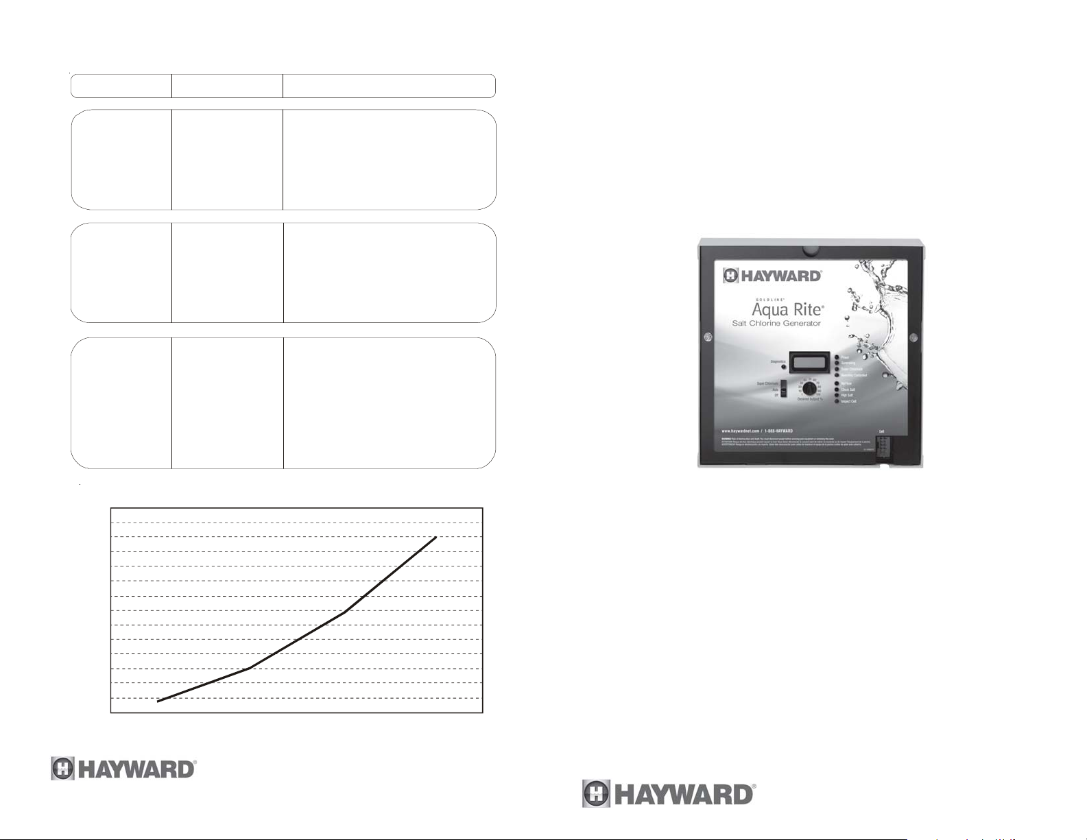
BASIC POOL MAINTENANCE REQUIREMENTS
TEST IDEAL RANGE ADJUSTMENT REQUIRED
Free Chlorine 1.0 - 3.0 ppm
pH 7.2 - 7.8
WEEKLY
Raise desired output % to
increase, lower desired out put %
to decrease -OR- increase or
decrease pump filtration time.
Too high - add muriatic acid
Too low - add soda ash.
Alkalinity 80 - 120 ppm
Add baking soda to increase.
dd acid as required to decrease.
MONTHL Y
Salt 2700 - 3400 ppm Add salt as required to increase.
Stabilizer 60 - 80 ppm Add cyanuric acid to increase.
Calcium 200 - 400 ppm Add calcium to increase.
QUARTERL Y
Electrolytic Cell inspect & clean Refer to section in manual.
Drain and add water to decrease.
Head Loss Curve
14
13
12
11
2
10
9
(FtH O)
8
7
6
5
4
Head Loss
3
2
1
0
.82
40 (25%)
3.08
6.79
120 (75%)80 (50%) 160 (100%)
12.03
®
Aqua Rite
Electronic Chlorine Generator
Operation and Installation
Manual
AQR
Flow Rate
620 Division St.
Elizabeth, NJ 07207
(gpm)
Copyright © 2010 Hayward Inc.
092009N RevP
www.haywardnet.com
Page 2

IMPORTANT SAFETY INSTRUCTIONS
When using this electrical equipment, basic safety precautions
should always be followed, including the following:
• READ AND FOLLOW ALL
INSTRUCTIONS
• Use Copper Conductors Only
• Disconnect all AC power during inst allation.
• Warning - To reduce the risk of injury, do not permit
children to use this product unless they are closely
supervised at all times.
• A green colored terminal marked "Earth Ground" is lo-
cated inside the wiring compartment. To reduce the risk
of electric shock, this terminal must be connected to the
grounding means provided in the electric supply service
panel with a continuous copper wire equivalent in size to
the circuit conductors supplying the equipment.
• One bonding lug for US models (two for Canadian mod-
els) is provided on the external surface. To reduce the
risk of electric shock, connect the local common bonding
grid in the area of the swimming pool, spa, or hot tub to
these terminals with an insulated or bare copper conductor not smaller than 8 AWG US / 6 AWG Canada.
• All field installed metal components such as rails, ladders,
drains, or other similar hardware within 3 meters of the
pool, spa or hot tub shall be bonded to the equipment
grounding bus with copper conductors not smaller than 8
AWG US / 6 AWG Canada.
• NOTICE TO USERS: This control product is to be used
only in accordance with the directions of this label. It is
an offense under the Pest Control Products Act to use a
control product under unsafe conditions.
• SAVE THESE INSTRUCTIONS
LIMITED W ARRANTY (effective 04/01/09) Hayward/Goldline warrants its Pro Logic and
E-Command pool automation products as well as its Aqua Rite, Aqua Rite Pro, Aqua Plus and
SwimPure chlorination products to be free of defects in materials and workmanship, under
normal use and service, for a period of three (3) years. Hayward/Goldline also warrants its
Aqua Trol chlorination products to be free of defects in materials and workmanship, under
normal use and service for a period of one (1) year. These warranties are applicable from the
initial date of installation on private residential swimming pools in the US and Canada.
Hayward/Goldline warrants all the above-identified pool automation and chlorination products installed on commercial swimming pools and on swimming pools outside of the US and
Canada for a period of one (1) year. Likewise, Hayward/Goldline warrants all accessories
and replacement parts for the above-identified pool automation and chlorination products for
a period of one (1) year. Each of these warranties is not transferable and applies only to the
original owner.
Proof of purchase is required for warranty service. If written proof of purchase is not
provided, the manufacturing date code will be the sole determinant of the date of installation
of the product. To obtain warranty service or repair, please contact the place of purchase or
the nearest Hayward/Goldline authorized warranty service center. For more information on
authorized service centers please contact the Hayward/Goldline Technical Service Support
Center (61 Whitecap Road, North Kingstown RI, 02852) or visit the Goldline web site at
www.goldlinecontrols.com or the Hayward website at www.haywardnet.com.
W ARRANTY EXCLUSIONS:
1. Material supplied or workmanship performed by others in process of installation.
2. Damage resulting from improper installation including installation on pools larger than the
product rating.
3. Problems resulting from failure to install, operate or maintain the product(s) in accordance
with the recommendations contained in the owners manual(s).
4. Problems resulting from failure to maintain pool water chemistry in accordance with the
recommendations in the owners manual(s).
5. Problems resulting from tampering, accident, abuse, negligence, unauthorized repairs or
alternations, fire, flood, lightning, freezing, external water, degradation of natural stone used in
or immediately adjacent to a pool or spa, war or acts of God.
DISCLAIMER. THE EXPRESS LIMITED W ARRANTIES ABOVE CONSTITUTE THE
ENTIRE W ARRANTIES WITH RESPECT TO THE ABOVE-IDENTIFIED HA YW ARD/
GOLDLINE POOL AUTOMA TION AND CHLORINATION PRODUCTS AND IS IN
LIEU OF ALL OTHER W ARRANTIES, EXPRESS OR IMPLIED, INCLUDING WARRANTIES OF MERCHANT ABILITY OR FITNESS FOR A P AR TICULAR PURPOSE.
THESE W ARRANTIES GIVE YOU SPECIFIC LEGAL RIGHTS, AND YOU MA Y ALSO
HA VE OTHER RIGHTS OF EQUIPMENT , LOST PROFITS OR REVENUE, COSTS
OF RENTING REPLACEMENTS, AND OTHER ADDITIONAL EXPENSES, EVEN IF
THE SELLER HAD BEEN ADVISED OF THE POSSIBILITY OF SUCH DAMAGES.
SOME STATES DO NOT ALLOW THE EXCLUSION OF LIMITATION OF INCIDENTAL OR CONSEQUENTIAL DAMAGES, SO THE ABOVE LIMITATION OR
EXCLUSION MA Y NOT APPLY TO YOU.
NO WHOLESALER, AGENT, DEALER, CONTRACTOR OR OTHER PERSON IS
AUTHORIZED TO PROVIDE, SUPPLEMENT OR MODIFY ANY WARRANTY ON
BEHALF OF HA YW ARD/GOLDLINE.
THESE W ARRANTIES ARE VOID IF THE PRODUCT HAS BEEN ALTERED IN ANY
W A Y AFTER LEAVING THE F ACTORY . FOR THE ABOVE-IDENTIFIED CHLORINATION PRODUCTS, THESE WARRANTIES ALSO ARE V OID IF, DURING THE
W ARRANTY PERIOD, YOU USE A REPLACEMENT CHLORINA TOR CELL OTHER
THAN AN UNMODIFIED, NEW HA YWARD/GOLDLINE CHLORINA TOR CELL PURCHASED FROM HA YW ARD/GOLDLINE. IF A WARRANTY BECOMES V OID, YOU
STILL MAY PURCHASE SERVICE AND/OR TELEPHONE TECHNICAL SUPPOR T
A T THE THEN CURRENT TIME AND MATERIAL RATES.
16
Page 3

4. "Check Salt" LED illuminated or flashing
Be sure that the correct model Turbo Cell has been selected (page 7).
Check salt level in pool/spa. If salt level is low, add salt according to chart on page 4.
Before adding large quantities of salt, it is advisable to have your salt level professionally checked.
5. "High Salt" LED illuminated
Be sure that the correct model Turbo Cell has been selected (page 7).
Check salt level in pool/spa. If salt level is too high, lower salt level by draining some of
the pool water out of the pool and replace with fresh water. Continue until the salt
concentration is at recommended levels.
6. "Inspect Cell" LED flashing
Be sure that the correct model Turbo Cell has been selected (page 7).
Table of Contents
OPERATION
General.........................................................................................1
Inspect and clean cell according to directions on page 8. When done, press the "diagnostic" button for 3 seconds to stop the "Inspect Cell" LED flashing.
7. "Inspect Cell" LED illuminated
Be sure that the correct model Turbo Cell has been selected (page 7).
Remove and inspect the cell for scale. If the cell is scaled, follow the directions on page
8 for cell cleaning. If the pool has the proper amount of salt and the "Inspect Cell" LED
is still illuminated, the cell may be worn and need replacement.
8. Possible causes of little or no free chlorine residual
- Aqua Rite® switch in OFF position.
- Desired Output % adjustment setting is too low.
- Low stabilizer (Cyanuric Acid).
- Filter pump time too short (8 hours for average size pools, more for large pools)
- Salt level too low (below 2400 ppm, Check Salt LED on).
- Salt level too high (High Salt LED on).
- V ery warm pools increase chlorine demand--increase Output %, or filter run time.
- Cold water (below 50ºF) causes Aqua Rite to stop generating (Generating LED flashing).
- Excessive scaling on cell.
- High level of Nitrogen in pool water.
- "Y ellow Out" or similar treatment recently used. Some yellow algae treatments will
use chlorine at a very high rate and deplete the residual free chlorine. Manually shock
the pool if indicated in the directions on the algae treatment. It still may be a matter of
days before the pool returns to "normal" and chlorine tests will show the desired 13ppm free chlorine reading.
9. "-Pcb-" displayed and all 4 red/yellow LEDs are illuminated.
A possible Printed Circuit Board fault has been detected. Call for
service.
Water Chemistry........................................................................2
Controls........................................................................................6
Maintenance.................................................................................8
INSTALLATION
Mounting........................................................................................10
Plumbing.......................................................................................11
Wiring............................................................................................12
TROUBLESHOOTING
Troubleshooting.........................................................................14
WARRANTY
Warranty......................................................................................16
15
Page 4

OPERA TION
The Aqua Rite® is an automatic chlorine generation system for pool or spa sanitation.
The operation requires a low concentration of salt (sodium chloride) in the pool water.
These levels are low enough that it normally will not be tasted. The Aqua Rite automatically sanitizes your pool by converting the salt into free chlorine which kills bacteria and
algae in the pool. Chlorine will revert back to sodium chloride after killing bacteria.
These reactions will continuously recycle virtually eliminating the need to add sanitizing chemicals to your pool. The only time you may need to add more salt to the pool is
when water is replenished due to backwashing, draining, or splashing (not evaporation).
Polaris - Attach wires to proper screw terminals as shown below. Note that screw
terminal "1" is marked on the Polaris PCB.
note
marked
on PCB
1
Eos
Aqua Rite
GRN
YEL
BLK
RED
4
3
2
1
black
yellow
green
red
The Aqua Rite is designed to handle the purification needs of most residential swimming pools up to 40,000 gallons (150,000 liters), or the needs of most commercial pools
up to 25,000 gallons (95,000 liters). Check local codes for other restrictions. The actual
amount of chlorination required to properly sanitize a pool varies due to bather load,
rainfall, temperature, and the pool's cleanliness.
NOTE: Hayward does not recommend using the Aqua Rite to generate bromine.
Aqua Rite chlorine generators operating with software version 1.50 or later are designed
to use one of 3 different chlorinator cells that are available from your authorized Hayward dealer. These cells are not included with the Aqua Rite and must be purchased
before installation. Choose the appropriate cell based on the size of your pool. The
models are shown below:
T -CELL-15- for pools up to 40,000 gallons
T -CELL-9 - for pools up to 25,000 gallons
T -CELL-3 - for pools up to 15,000 gallons
Note that the installation and mounting requirements are the same for all models.
NOTE: Before installing this product as part of a saline water purification system in a
pool or spa using natural stone for coping or for immediately adjacent patios/decking, a
qualified stone installation specialist should be consulted regarding the appropriate
type, installation, sealant (if any) and maintenance of stone used around a saline pool
with electronic chlorine generator in your particular location and circumstances.
NOTE: The use of dry acid (sodium bisulfate) to adjust pool pH is discouraged especially in arid regions where pool water is subject to excessive evaporation and is not
commonly diluted with fresh water. Dry acid can cause a buildup of by-products that
can damage your chlorinator cell.
TROUBLESHOOTING
V isit www.goldlinecontr ols.com for helpful information on operation, maintenance and
troubleshooting your Aqua Rite® Electronic Chlorine Generator.
Diagnostic Displays
Sequential pushes of the small "diagnostic" button next to the LCD display will cause
the Aqua Rite to display the following information:
1. Pool temperature (xx degrees Fahrenheit or Celsius)
2. Cell voltage (xx.x volts)
3. Cell current (x.xx amps)
4. Desired Output % ("0P" -- "100P" depending on knob position or input from remote
pool automation controller)
5. Instant salinity ( -xxxx ppm or -x.xx grams/Liter)
6. Product name sent to the pool automation control display ("AL-0" which signifies
"Aqua Rite")
7. Software revision level (r1.xx)
8 . Chlorinator cell type (t-3, t-5, t-9, t-15)
On the 9th push of the button the display will revert back to the default salt display.
Also, if the button is not pushed for 30 seconds, the display will revert back to the
standard salt display.
Common Problems and Solutions
1. "Power" LED not on
Check to make sure either 120VAC or 240VAC input power is connected to the proper
screw terminals at the Aqua Rite control. Verify input voltage with a voltmeter. If there
is input power, the fuse may have blown. The Aqua Rite is protected by a 20 amp mini
ATO fuse located on the circuit board above the cell connector.
2. "Generating" LED flashing
The temperature of the pool water is too high or low to operate. You can override this by
switching the main switch to SUPER CHLORINA TE. The Aqua Rite will run at maximum
output for the remainder of the current pump cycle or 24 hours, whichever comes first.
3. "No Flow" LED illuminated
The Aqua Rite has sensed a no flow condition and has stopped generating chlorine.
Check that the flow switch is plugged into the connector on the bottom of the control
unit and that the wire is not cut or damaged. Make sure you have at least 12" of straight
pipe before the flow switch. If there is adequate flow and the LED is still on, check that
the arrows on the flow switch (on top of hex) are pointing in the direction of flow.
1
14
Page 5
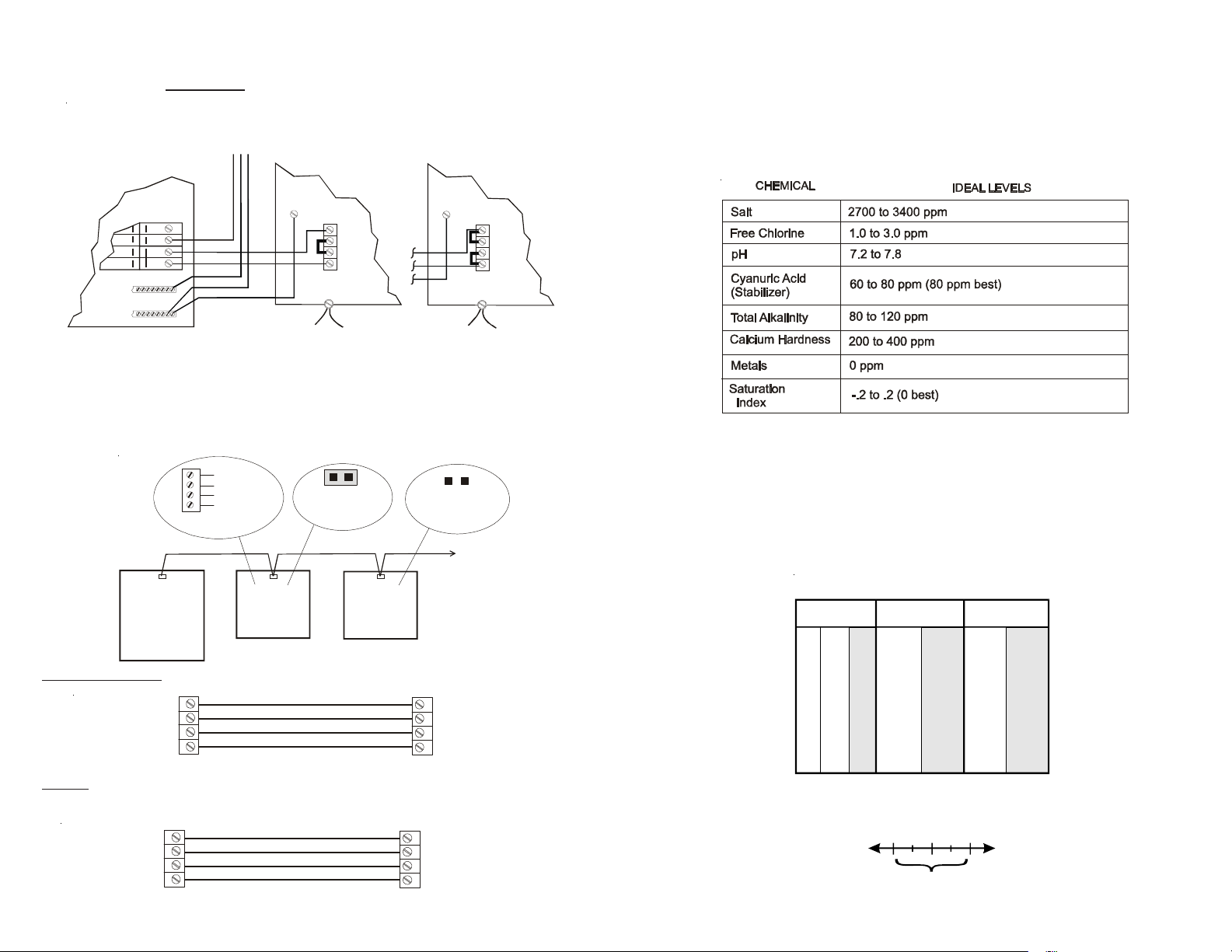
Input power for use with Hayward/Goldline, Pentair and
A
Polaris controls
Wire the Aqua Rite® DIRECTL Y to 120/240V AC power (not through timer or relay).
HAYWARD/GOLDLINE,
PENTAIR
or
POLARIS
AQUA RITE
(240 VAC)
AQUA RITE
(120 VAC)
Water Chemistry
The table below summarizes the levels that are recommended by The Association of
Pool and Spa Professionals (APSP). The only special requirements for the Aqua Rite
are the salt level and stabilizer. It is important to maintain these levels in order to
prevent corrosion or scaling and to ensure maximum enjoyment of the pool. T est your
water periodically . Your Authorized Aqua Rite Dealer (AARD) or most pool stores can
provide you with the chemicals and procedures to adjust the water chemistry . Be sure
to tell the pool store that you are using an Aqua Rite chlorine generator.
SUBPANEL
GND GND
NEUTRAL
GROUND
PCB
BONDING
LOOP
PCB
BONDING
LOOP
Optional Hayward/Goldline, Pentair and Polaris controls:
The Hayward/Goldline, Pentair and Polaris controls use a 4 wire connection to communicate to the Aqua Rite and can be wired up to 500' apart. Any outdoor rated 4 conductor
cable can be used. Refer to each manufacturer's instructions and the wiring diagrams
below for proper wiring connection to the Aqua Rite. NOTE: There must be only 1
"primary" unit. All other Aqua Rite units must be configured as "secondary".
GREEN
4
3
Hayward/Goldline,
Pentair
or Polaris
Power Center
2
1
YELLOW
BLACK
RED
Aqua Rite
(Primary)
Jumper Installed
For Primary
(Factory Default)
Aqua Rite
(Secondary)
Jumper Removed
For Secondary(s)
Additional
Aqua Rite(s)
(if required)
Hayward/Goldline - Attach wires to proper screw terminals as shown below.
green
yellow
black
red
4
3
2
1
GRN
YEL
BLK
RED
Pro Logic
qua Logic
Aqua Rite
GRN
YEL
BLK
RED
4
3
2
1
Pentair - Attach wires to opposite numbered screw terminals as shown below. Note
that the colors marked on the Pentair PCB do not match the Aqua Rite.
marking on PCB
BLK / GND
1
2
GRN / -DT
YEL / +DT
3
RED / +15
4
Intellitouch
Aqua Rite
GRN
YEL
BLK
RED
4
3
2
1
(Colors Do Not Match)
green
yellow
black
red
Saturation index
The saturation index (Si) relates to the calcium and alkalinity in the water and is an
indicator of the pool water "balance". Your water is properly balanced if the Si is 0 ±.2.
If the Si is below -0.2, the water is corrosive and plaster pool walls will be dissolved into
the water . If the Si is above +0.2, scaling and staining will occur. Use the chart below to
determine the saturation index.
Si = pH + Ti + Ci + Ai - 12.1
ºC ºF Ti
12
53
16
60
19
66
24
76
29
84
34
94
39
103
How to use: Measure pool pH, temperature, cal cium hardness ,
and total alkalinity. Use the chart above to determine Ti, Ci,and
Ai from your measurements. Insert values of pH, Ti, Ci and Ai
into the above equation. If Si equals . 2 or more, scaling and
staining may occur. If Si equals -.2 or less corrosion or irritation
may occur.
CORROSIVE SCALING
Calcuim
Hardness
.3
75 75
100 100
.4
125 125
150 150
.5
200 200
.6
250 250
300 300
.7
400 400
.8
600 600
800 800
.9
-.2
OK
Total
Ci
Alkalinity
1.5 1.9
1.6 2.0
1.7 2.1
1.8 2.2
1.9 2.3
2.0 2.4
2.1 2.5
2.2 2.6
2.4 2.8
2.5 2.9
0.2
Ai
13
2
Page 6
Salt Level
r
C
Use the chart on page 4 to determine how much salt in pounds or (Kgs) need to be added
to reach the recommended levels. Use the equations below (measurements are in feet/
gallons and meters/liters) if pool size is unknown.
Liters
(pool size in meters)
Rectangular
Round
Oval
Gallons
(pool size in feet)
Length x Width x
Average Depth x 7.5
Diameter x Diameter x
Average Depth x 5.9
Length x Width x
Average Depth x 6.7
Length x Width x
Average Depth x 1000
Diameter x Diameter x
Average Depth x 785
Length x Width x
Average Depth x 893
The ideal salt level is between 2700-3400 ppm (parts per million) with 3200 ppm being
optimal. If the level is low, determine the number of gallons in the pool and add salt
according to the chart on page 4. A low salt level will reduce the ef ficiency of the Aqua
Rite® and result in low chlorine production. A high salt level can cause the Aqua Rite
to shutdown and may begin to give a salty taste to your pool (generally, the salt will
begin to be tasted at a level of about 3500-4000 ppm). The salt in your pool/spa is
constantly recycled and the loss of salt throughout the swimming season should be
small. This loss is due primarily to the addition of water because of splashing,
backwashing, or draining (because of rain). Salt is not lost due to evaporation.
T ype of Salt to Use
It is important to use only sodium chloride (NaCl) salt that is greater than 99% pure. This
is common food quality or water softener salt and is usually available in 40-80 lb. bags
labeled "Coarse Solar Salt". It is also acceptable to use water conditioning salt pellets,
however, it will take longer for them to dissolve. Do not use rock salt, salt with yellow
prussiate of soda, salt with anti-caking additives, or iodized salt.
How to Add or Remove Salt
For new plaster pools, wait 10-14 days before adding salt to allow the plaster to cure.
Turn the circulating pump on and add salt directly into the pool. Brush the salt around
to speed up the dissolving process--do not allow salt to pile up on the bottom of the
pool. Run the filter pump for 24 hours with the suction coming from the main drain (use
pool vac if there is no main drain) to allow the salt to evenly disperse throughout the
pool. The salt display may take 24 hours to respond to the change in salt concentration.
The only way to lower the salt concentration is to partially drain the pool and refill with
fresh water.
Wiring
Power must be shut off at the circuit breaker before performing any wiring. Be sure to
follow Local and NEC electrical codes. T o provide safe operation, the Aqua Rite® must
be properly grounded and bonded.
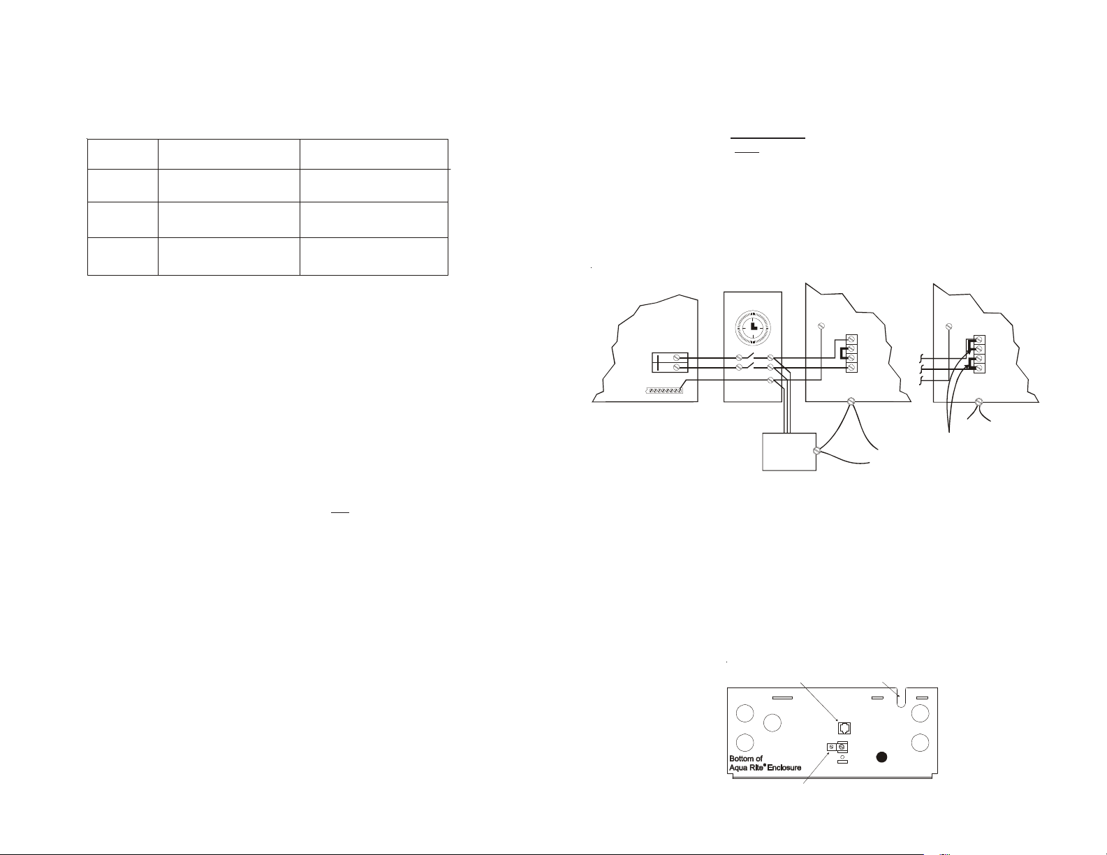
Input Power For stand alone operation:
Wire the Aqua Rite to the LOAD SIDE of the filter pump timer . It is very important that
the Aqua Rite is powered only when the pump is running.
Refer to the wiring label on the Aqua Rite as well as the diagram below to determine
correct wiring connections. The Aqua Rite is shipped from the factory with the configuration jumpers in 240V AC position. If using 120VAC, move the jumpers as shown below .
For Canadian models, the Aqua Rite shall be connected to a circuit protected by a class
A ground fault interrupter. Be sure to connect the ground wire to the green ground
screw terminal located on the bottom of the enclosure.
TYPICAL 240 VAC WIRING
TIMECLOCK
SUBPANEL
®
GROUND
Note: Wire the pump directly to the timeclock--do not use the Aqua Rite as a junction box.
LINE LOAD
PUMP
AQUA
RITE
GND
PCB
BONDING
LUG
BONDING
LOOP
Bonding:
A lug used for bonding is attached to the bottom of the Aqua Rite enclosure (see
diagram below). The Aqua Rite must be bonded with an 8 AWG copper wire (6 AWG
Canada) to the pool bonding system.
Electrolytic Cell and Flow Switch:
The electrolytic cell and flow switch cables are terminated with connectors which plug
into the Aqua Rite, for easy attachment and removal. The door of the Aqua Rite must be
open to access the cell cable connector. The flow switch plugs into a connector (similar
to a telephone jack) located outside, on the bottom of the enclosure. Refer to the
diagram below for the location of these connections.
Flow switch connector
Cutout fo
cell cable
120 VA
AQUA
RITE
GND
PCB
IMPORTANT:
MOVE JUMPERS
TO POSITIONS SHOWN
Always check stabilizer (cyanuric acid), when checking salt. These levels will most
likely decline together. Use the chart on page 5 to determine how much stabilizer must
be added to raise the level to 80 ppm.
3
Bonding lug to
pool bonding system
12
Page 7
Plumbing
Ensure that the Aqua Rite® installation does not constitute a cross connection with the
local potable water supply. Consult local plumbing codes.
The Aqua Rite is packaged with a flow switch and cell unions. The cell must be purchased separately . Refer to page 1 for information about available chlorinator cells.
The flow switch and cell should be plumbed in the return line to the pool/spa. The
preferred installation is after (downstream) all the pool equipment (filter, heater, solar,
etc.). The electrolytic cell and flow switch tee fitting are designed to be plumbed into 2"
(51mm) PVC pipe. Adapters (not included) can be used for systems with 1½" (38 mm)
plumbing.
(398)
267
67
63
127
190
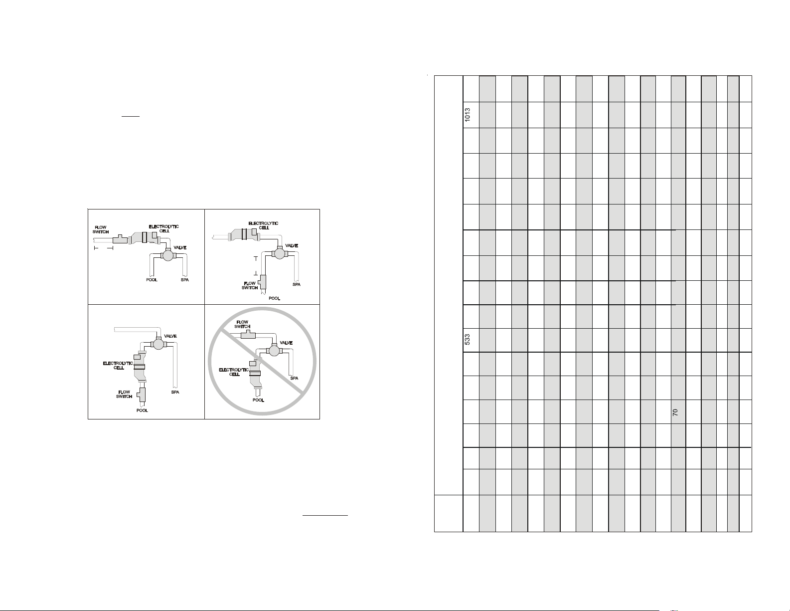
For proper plumbing, refer to the overview diagram on page 9. Alternate configurations
#1 shows the flow switch can also be in front of the cell. Configurations #2 and #3 allow
for chlorination of both the pool and spa during spa spillover operation, but prevent
overchlorination of the spa during "spa only" operation. Never use configuration #4.
min
1
12”
12”
min
3
2
4
Flow Switch: IMPORT ANT : There must be at least a 12" (25cm) straight pipe run
before (upstream) the flow switch. If the switch is plumbed after the
cell, the cell can by counted as the 12" (25cm) of straight pipe. To
ensure proper operation, verify that the arrow on the flow switch
(located on top of gray hex) points in the direction of water flow.
(68) (90)
(64) (86)
(59) (81)
(55) (77)
(50) (73)
(45)
(41)
(36)
(32)
(27)
(18) (23)
100 133
93
87 120
80 113
73 107
67
60
53
47
40
27 33
(45) (60)
(42) (57)
(39) (54 )
(36) (51)
(33) (48)
(30)
(27)
(24)
(21)
(18)
(15)
(12)
57
50
47
43 60
40
37 53
33
30
27
23
20
13 17
(23) (30)
(21) (29)
(20) (27)
(18) (26)
(17) (24)
(15)
(14)
(12)
(11)
(9)
(6) (8)
Ideal Ideal Ideal Ideal Ideal Ideal IdealIdeal IdealIdeal IdealIdeal IdealIdeal Ideal
Ideal
Ideal
OK OK OK OK OKOK OKOK OKOK OKOK OK
OK
OK
OK
OK
Dilute Dilute Dilute Dilute Dilute Dilute DiluteDilute DiluteDilute DiluteDilute DiluteDilute Dilute
Dilute
Dilute
(195)
(182) (243)
(170) (231)
(158) (219)
(145) (207)
(133)
(121)
(109)
(97)
(85)
(73)
(48) (61)
350 467
327 443
303 420
280 397
257 373
233
210
187
163
140
93 117
(159) (211)
(148) (201)
(138) (190)
(127) (180)
(117) (169)
(106)
(95)
(85)
(74)
(64)
(42) (53)
340
300 400
280 380
260 360
240
220 320
200
180
160
140
120
80 100
(310)
(363)
(341) (453)
(318) (430)
(295) (408)
(273) (385)
(250)
(227)
(205)
(182)
(159)
(136)
(91) (114)
650 867
700 933
(318) (424)
607 823
653 887
(297) (403)
563 780
607 840
(276) (382)
520 737
560 793
(255) (360)
477 693
513 747
(233) (339)
433
467
(212)
390
420
(191)
347
373
(170)
303
327
(148)
260
280
(127)
217
(106)
173
(85)
187 233
(297)
(276) (378)
(256) (358)
(236) (337)
(217) (317)
(197)
(177)
(158)
(138)
(118)
(98)
(79)
600 800
560 760
520 720
480 680
440 640
400
360
320
280
240
160 200
(273) (364)
(255) (346)
(236) (328)
(218)
(200) (291)
(182)
(164)
(145)
(127)
(109)
(91)
(73)
550 733
500 667
450 600
(227) (304)
(212) (289)
(197) (274)
(182) (258)
(167) (243)
(152)
(136)
(121)
(106)
(91)
(61) (76)
400 533
(205) (263)
420 570
373 507
(191) (259)
390 540
347 480
(177) (246)
360 510
320 453
(164) (232)
330 48 0
293 427
(150) (218)
300
267
(136)
270
240
(123)
240
213
(109)
(95)
210
187
(82)
180
160
(55) (68)
120 150
107 13 3
(250) (333)
513 697
467 633
(233) (317)
477 660
433 600
(217) (300)
440 623
400 567
(200) (283)
403 587
367 533
(183) (267)
367
333
(167)
330
300
(150)
293
267
(133)
(117)
257
233
220
200
(100)
(67) (83)
147 183
133 167
800 1067
750 1000
(364) (484)
747
700 950
(339) (460)
693 960
650 900
(315) (436)
640 907
600 850
(291) (412)
587 854
550 800
(267) (388)
500
480
450
(218) (242)
Gallons an d (Liters) of Pool/Spa water
427
POUNDS and (Kg) OF SALT NEEDED FOR 3200 PPM
12,000 14,000 16,000 18,000 20,000 22,000 32,00024,000 34,00026,000 36,00028,000 38,00030,000 40,000
10,000
8,000
400
(194)
373
350
(170)
320
300
(145)
(45000) (52,500) (60,000) (67,500) (75,000) (82,500) (120,000)(90,000) (127,500)(97,500) (135,000)(105,000) (142,500)(112,500) (150,000)ppm
267
(121)
(37,500)
(97)
213
200 250
(30,000)
(136) (181)
(127) (172)
(118) (163)
(109) (154)
(100) (145)
(91)
(82)
(73)
(64)
(55)
(36) (45)
227
(91) (123)
150 200
200
250 333
(114) (152)
187 253
(85) (117)
233 317
140
(106) (144)
(98) (137)
(79) (110)
173 240
217 300
130 180
(91) (129)
(73) (104)
120 170
160
200 283
(83) (121)
(67) (98)
110 160
183 267
147 213
(76)
(61)
133
167
100
(68)
90
(55)
150
120
80
(61)
(48)
107
133
(53)
93
117
(42)
80
60
(36)
(45)
100
67
40 50
67 83
53
(30) (38)
(24) (30)
Electrolytic Cell: Install using the unions provided. Tighten unions BY HAND for a
watertight seal. For pool/spa combination systems with spillover,
use configurations #2 or #3 above to allow chlorination of both the
pool and spa during spillover but preventing overchlorination when
operating the spa only.
0
level
Current salt
400
200
600
800
1000
1200
1400
1600
1800
2000
2400
2200
3000
2800
3200
3400
3600+
2600
411
Page 8
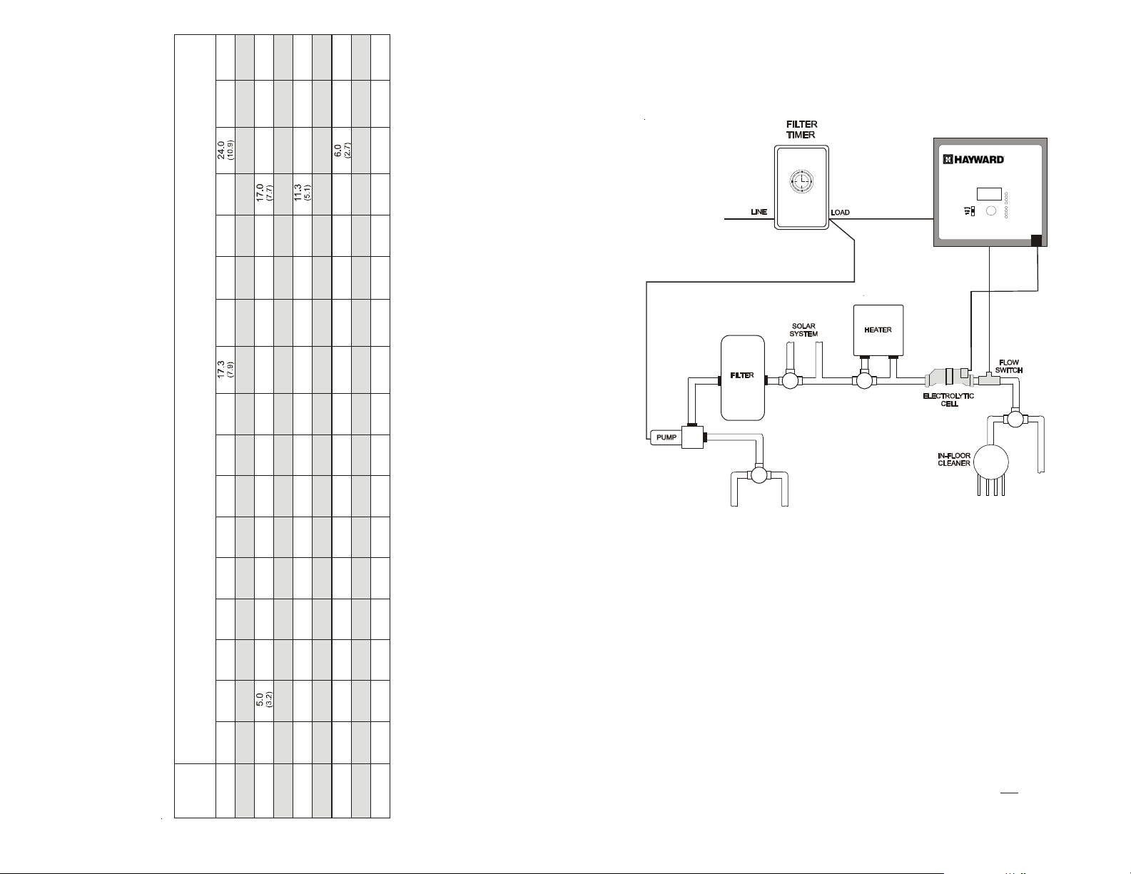
6.7
(7.5)
(9.0)
23.3
26.7
20.0
(10.5)
(12.0)
40,000
(150000)
(6.0)
16.7
13.3
3.3
(4.5)
(3.0)
10.0
(1.5)
INSTALLA TION
9.5
6.3
(7.1)
(8.6)
22.2
19.0
25.3
(10.0)
(11.5)
38,000
(142500)
(9.5)
21.0
36,000
(135000)
34,000
(127500)
32,000
(120000)
30,000
(112500)
28,000
(105000)
26,000
(97500)
24,000
(90000)
22,000
(82500)
20,000
(75000)
Gallons and (Liters) of Pool/Spa water
18,000
(67500)
18.0
(9.0)
19.8
22.7
(10.3)
(8.5)
(9.7)
18.7
16.0
21.3
(8.0)
(9.1)
17.2
20.0
15.0
(7.4)
(8.5)
16.4
18.7
14.0
(6.9)
15.2
13.0
(6.4)
(7.3)
14.0
16.0
12.0
(5.9)
(6.7)
11.0
12.9
14.7
(5.3)
(6.1)
11.7
10.0
13.4
9.0
(4.8)
(5.4)
10.5
12.0
(5.7)
15.8
12.7
(6.7)
(8.1)
(5.4)
15.0
12.0
(6.3)
14.2
(7.2)
(4.8)
(6.0)
10.7
13.3
(5.6)
(6.8)
(4.5)
12.5
10.0
9.3
(5.2)
(6.4)
11.7
(4.2)
8.7
(4.9)
(5.9)
(3.9)
10.8
8.0
(3.6)
(4.5)
(5.4)
10.0
7.4
9.2
(5.0)
(3.3)
(4.2)
8.4
(4.5)
6.7
(3.8)
(3.0)
6.0
7.5
(2.7)
(2.2)
(3.4)
3.2
(4.3)
(2.8)
(1.4)
9.0
3.0
(4.1)
(1.3)
8.5
5.7
2.8
(3.9)
(1.3)
(2.6)
8.0
5.3
(3.6)
7.5
5.0
(3.4)
7.0
4.7
(3.2)
6.5
4.3
(2.9)
6.0
4.0
(2.7)
5.5
3.7
(2.5)
3.3
5.0
(2.3)
4.5
(2.0)
0.00.0 0.00.0 0.00.0 0.00.0 0.0
2.7
(2.4)
(1.2)
2.5
(2.3)
(1.2)
2.3
(2.1)
(1.1)
2.2
(2.0)
(1.0)
2.0
(1.8)
(.91)
1.8
(1.7)
(.82)
1.7
(1.5)
(.77)
1.5
3.0
(.68)
(1.4)
Installation must be performed in accordance with Local and NEC codes.
AQUA
RITE
Aqua Rite
120/240 VAC
POWER
FROM
POOL
FROM
SPA
LDLIN E
G
CONTROLS INC.
TO
POOL
TO
SPA
6.7
9.4
8.0
(4.9)
10.7
16,000
(60000)
POUNDS and (Kg) OF STABILIZER (CYANURIC ACID) NEEDED FOR 80 PPM
14,000
9.4
(52500)
8.2
(4.3)
(3.0)
(4.3)
(3.6)
5.9
7.0
(3.7)
(2.7)
(3.2)
2.7
5.4
(2.4)
4.7
(2.1)
1.4
4.0
(1.2)
(.64)
(1.8)
3.5
2.3
1.2
(1.6)
(1.1)
(.54)
)
7.0
5.0
12,000
10,000
8.0
(45000)
6.7
(37500)
6.0
(3.6)
(3.2
(2.7)
5.8
(3.7)
(4.3)
3.0
2.0
4.0
(2.3)
(1.8)
4.2
3.3
(2.7)
(2.1)
1.0
(1.4)
2.5
1.7
(1.6)
0.00.0 0.00.0 0.0 0.0 0.0 0.0
(.91)
(.45)
0.8
(1.1)
(.54)
Preparing Pool/Sp a Water
Refer to page 1 for recommended chemical levels. The pool's chemistry must be balanced BEFORE activating the Aqua Rite®. NOTE: If the pool does not have new water,
add 1 quart (1 liter) of metal remover and 1 quart (1 liter) of non-copper based algaecide
to the pool, per manufacturer's instructions. This ensures a quick, troublefree transfer
to the Aqua Rite system.
Mounting the Aqua Rite Control
The Aqua Rite is contained in a raintight enclosure that is suitable for outdoor mounting. The control must be mounted a minimum of 5 ft. (2 meters) horizontal distance (or
more, if local codes require) from the pool/spa.
4.7
3.3
4.0
5.3
(3.2)
(3.6)
8,000
(30000)
2.7
(2.3)
(2.7)
(1.8)
0.7
2.0
1.3
(.45)
(.91)
(1.4)
The control is designed to mount vertically on a flat surface with the knockouts facing
downward. Because the enclosure also acts as a heat sink (disperses heat from inside
the box), it is important not to block the four sides of the control. Do not mount Aqua
Current
0 ppm
20 ppm
30 ppm
Stabilizer
10 ppm
Level (ppm)
60 ppm
40 ppm
50 ppm
70 ppm
80 ppm
Rite inside a panel or tight enclosed area.
5 10
Page 9

The Aqua Rite electrolytic cell has a self cleaning feature incorporated into the electronic control’s logic. In most cases this self cleaning action will keep the cell working
at optimum efficiency . In areas where water is hard (high mineral content) and in pools
where the water chemistry has been allowed to get "out of balance", the cell may require
periodic cleaning. The "Inspect Cell" LED will indicate if cell efficiency is decreased and
servicing is necessary . If the "Inspect Cell" LED remains on after a thorough cleaning,
the cell may be worn and require replacement.
Servicing and Cleaning the Aqua Rite cell
Turn off power to the Aqua Rite before removing the electrolytic cell. Once removed,
look inside the cell and inspect for scale formation (light colored crusty or flaky deposits) on the plates and for any debris which has passed through the filter and caught on
the plates. If no deposits are visible, reinstall. If deposits are seen, use a high pressure
garden hose and try to flush the scale off. If this is not successful, use a plastic or wood
tool (do not use metal as this will scratch the coating off the plates) and scrape deposits
off of plates. Note that a buildup on the cell indicates that there is an unusually high
calcium level in the pool (old pool water is usually the cause). If this is not corrected,
you may to have to periodically clean the cell. The simplest way to avoid this is to bring
the pool chemistry to the recommended levels as specified.
Mild Acid Washing: Use only in severe cases where flushing and scraping will not
remove the majority of deposits. T o acid wash, turn off power to Aqua Rite. Remove cell
from piping. In a clean plastic container, mix a 4:1 solution of water to muriatic acid (one
gallon of water to one quart of muriatic acid). ALWAYS ADD ACID TO WATER NEVER ADD WA TER TO ACID. Be sure to wear rubber gloves and appropriate eye
protection. The level of the solution in the container should just reach the top of the cell
so that the wire harness compartment is NOT submerged. It may be helpful to coil the
wiring before immersing the cell. The cell should soak for a few minutes and then rinse
with a high pressure garden hose. If any deposits are still visible, repeat soaking and
rinsing. Replace cell and inspect again periodically .
Winterizing
The Aqua Rite electrolytic cell and flow detection switch will be damaged by freezing
water just as your pool plumbing would. In areas of the country which experience
severe or extended periods of freezing temperatures, be sure to drain all water from the
pump, filter, and supply and return lines before any freezing conditions occur. The
electronic control is capable of withstanding any winter weather and should not be
removed.
Spring Start-up
DO NOT turn the Aqua Rite on, until the pool water chemistry has been brought to the
proper levels. This information can be found on page 1.
Controls
Main Switch
AUTO: For normal operation, the Main Switch should be left in the AUT O position.
In this position the Aqua Rite will produce chlorine according to the "Desired Output %" adjustment setting for the entire filtering/pumping cycle.
SUPER CHLORINA TE: When you have an abnormally high bather load, a lar ge
amount of rain, a cloudy water condition, or any other condition which needs a large
amount of purification to be introduced, put the Main Switch in the SUPER CHLORINA TE position. This electronically “super chlorinates” (shocks) the water for 24
hours (filter pump must be on during this time) or until the power has been turned
off, whichever comes first. At the end of the super chlorinate time, be sure to put the
switch back into the AUT O position.
OFF: The OFF position prevents the Aqua Rite from ener gizing the electrolytic cell.
In this position there is no chlorine generation. NOTE: To service any of the pool
equipment or the Aqua Rite, turn the power of f at the circuit breaker .
Indicator LED's
POWER When illuminated, the Aqua Rite has input power .
GENERA TING This LED is on steady during normal operation. When flashing, the
pool water is too hot or cold to operate.
SUPER CHLORINATE Illuminates during super-chlorination. See description
above.
REMOTEL Y CONTROLLED When illuminated, indicates that a remote pool auto-
mation control (Hayward/Goldline Pro Logic, Pentair Intellitouch, Polaris Eos, etc.)
is controlling the Aqua Rite--the main switch and "Desired Output %" adjustment
are inactive. When flashing, the Pro Logic, Intellitouch or Eos is in SERVICE or
TIME-OUT mode and the Main Switch and "Desired Output %" adjustment are
active.
NO FLOW When illuminated, the flow switch has detected no water flowing and
the Aqua Rite has stopped generating chlorine. A flashing LED indicates a 15-60
second time delay period.
CHECK SAL T When flashing, the salt level is low (below 2700 ppm) and Aqua Rite
is generating at low efficiency . When illuminated steady , the salt level is too low and
Aqua Rite has shut down. Before adding large quantities of salt, it is advisable to
have your salt level professionally checked.
HIGH SALT When illuminated, the salt level is too high and Aqua Rite has shut
down.
INSPECT CELL A flashing indicator signifies that either the cell efficiency is reduced or that it is time for regularly scheduled cell inspection. In either case, inspect
cell and clean if necessary. When illuminated steady, cell efficiency is greatly reduced and the Aqua Rite has stopped producing chlorine. Inspect, clean or replace
if necessary.
9
6
Page 10

T o Set T urbo Cell Type
Before operation, the Aqua Rite must be configured for the chlorinator cell that will be
used. Refer to the following information and steps below to set the Turbo cell type.
"t-3" = T -CELL-3, GLX-CELL-3-W
"t-5" = GLX-CELL-5, GLX-CELL-5-W
"t-9 = T -CELL-9, GLX-CELL-9-W
"t-15" = T -CELL-15, GLX-CELL-15-W
Operation
Assuming that the water chemical levels are in the recommended range, there are three
factors that you can control which directly contribute to the amount of chlorine the
Aqua Rite will generate:
1 . filter time each day (hours)
2. the "Desired Output %" setting
3. the amount of salt in the pool
1. Slide the Main Switch to the "Auto" position.
2 . Push the Diagnostic button repeatedly until "t-xx" appears on the display ("t-15" is
the factory default). If the desired cell type is displayed skip to step 4.
3. To change to a different cell type, slide the Main Switch from "Auto" to "Super
Chlorinate" and back to "Auto". Repeat this process until the desired cell type is
displayed.
4. Push the Diagnostic button to exit.
Desired Output %" adjustment knob
The "Desired Output %" adjustment knob is located in the lower center of the Aqua Rite
control panel. This setting is used to control the amount of chlorine the Aqua Rite
generates. Raise this setting to increase chlorine level and lower it to decrease chlorine
level. Note: The "Desired Output %" adjustment will not function when the Aqua Rite
is being controlled by a remote pool automation control.
Salt Display
Refer to the W ater Chemistry section for recommended salt levels as well as how to add/
remove salt. The Salt Display shows the average salt level of the pool water. The
factory default display is in English units (ppm). If Metric units (grams per liter) are
preferred, follow the procedure under T emperature Display .
T emperature Display
The T emperature Display shows the current temperature of the pool water . The factory
default display is in ºF. Both the Temperature Display and the Salt Display can be
programmed to display in Metric units. T o display temperature in ºC and salt level in g/
l, perform the following steps:
1. Slide the Main Switch to the "Auto" position.
2. Push the Diagnostic button repeatedly until "ºF" appears on the display.
3 . Slide the Main Switch from "Auto" to "Super Chlorinate" and back to "Auto".
4. Push the Diagnostic button to exit.
Instant Salinity
The Instant Salinity display is the measured salt level of the pool water at that moment.
If salt has recently been added, the Instant Salinity may show the change while the Salt
Display (average salt level) may take some time before the changes can be seen. Under
these circumstances, you may want to "update" the Salt Display to the new Instant
Salinity value. This action will clear the Salt Display and substitute the Instant Salinity
value. To do this, follow the steps below.
1. Slide the Main Switch to the "Auto" position.
2 . Push the Diagnostic button repeatedly until "-xxxx ppm" appears on the display.
3 . Slide the Main Switch from "Auto" to "Super Chlorinate" and back to "Auto".
4. Push the Diagnostic button to exit.
The filter pump timer should be set so that all of the water in the pool passes through
the filter each day . For pools with high chlorine demand, the timer may have to be set
longer to generate enough chlorine.
T o find the optimum "Desired Output %" setting, start at approximately 50%. Test the
chlorine level every few days and adjust the dial up or down accordingly. It usually
takes 2-3 adjustments to find the ideal setting for your pool/spa and after that, it should
only take minor, infrequent adjustments. Because the chlorine demand of the pool
increases with temperature, most people find they have to adjust the dial up at the peak
of the summer and down during the colder periods. The Aqua Rite automatically stops
generating when the pool water temperatures drops below 50ºF. This is usually not a
problem because bacteria and algae stop growing at this temperature. You can override
this low temperature cutoff by switching to SUPER CHLORINA TE for a day .
NOTE: After the ideal "Desired Output %" setting has been found, you may need to
raise the setting when the pool water temperature increases significantly, when there is
higher than normal bather load or when your chlorinator cell ages. You may need to
lower the setting when the pool water temperature decreases significantly or there are
long periods of inactivity .
Prevent over-chlorination during cold weather: Check chlorine levels periodically . Most
pools require less chlorine during cold weather and the “Desired Output %” should be
lowered accordingly.
When connected to a pool automation control (Hayward/Goldline Pro Logic, Pentair
Intellitouch or Polaris Eos):
The Aqua Rite is designed to operate with all pool automation controls. The Pro Logic,
Intellitouch or Eos can fully control the function of the Aqua Rite chlorinator in addition
to the other pool equipment. The "Remotely Controlled" LED on the Aqua Rite chlorinator will be illuminated when the automation control is activated. Adjustment of the
Aqua Rite "Desired Output %" and also Superchlorination can be controlled from the
pool automation display/keypad. Refer to the pool automation control instructions for
more information. The Aqua Rite salt display and LED indicators operate as normal, but
the main switch and "Desired Output %" dial are disabled.
Maintaining the Aqua Rite System
T o maintain maximum performance, it is recommended that you open and visually inspect the cell every 3 months or after cleaning your filter. The Aqua Rite® will remind
you to do this by flashing the "Inspect Cell" LED after approximately 500 hours of
operation. After you inspect the cell (and clean, if necessary) press the small "diagnostic" button next to the display for 3 seconds to stop the flashing "Inspect Cell" LED and
start the timer for the next 500 hours.
7 8
 Loading...