

Hayward AQL2-BASE-RF Owner's Manual

USE ONLY HAYWARD GENUINE REPLACEMENT PARTS
Hayward Pool Products
620 Division Street, Elizabeth NJ 07207
www.hayward.com
.....
Wireless Base Station
Owner’s Manual
AQL2-BASE-RF
Contents
Compatibility.........................1
Installation............................1
Operation..............................2
Troubleshooting....................3
Warranty................................6
092047D RevB
for Aqua Logic and Pro Logic
1
USE ONLY HAYWARD GENUINE REPLACEMENT PARTS
Compatibility
This product is compatible with all Pro Logic controls and with Aqua Logic controls operating software revision r2.60 or higher. To verify the software level of your Aqua Logic control: Press the
Menu button (possibly multiple times) until “Diagnostic Menu” is displayed. Next, press the “>” or
“<“ keys (possibly multiple times) until the main and display software revision levels are displayed
(the “main” rev should be r1.10 or higher).
If the software revision level is less than r2.60 contact the Hayward Technical Service Dept. from
Monday through Friday, 8AM to 8PM Eastern at 908-355-7995 for information on upgrades.
This Base Station can communicate with the spaside remote (AQL2-SS-RF), the wireless wall
mount and tabletop remote display/keypads (AQL2-Wx-RF-PS-x, AQL2-Tx-RF-PS-x, AQL2-Tx-RFP-4-x) and the Aqua Pod handheld remote control (AQL2-POD).
Installation
Installation is very easy and should just take a few minutes. For most installations the Base
Station will mount directly on the ProLogic or Aqua Logic main control unit (see description and
diagram below). For some installations where the remote devices are a long distance from the
Base Station or where there are interfering walls (eg. A steel shed in the yard or a steel reinforcing
grid inside a stucco wall on the house), the Base Station may have to be mounted remotely from
the control unit in order to achieve reliable communications. Refer to the instructions and diagram
on page 2 for more information regarding remote mounting.
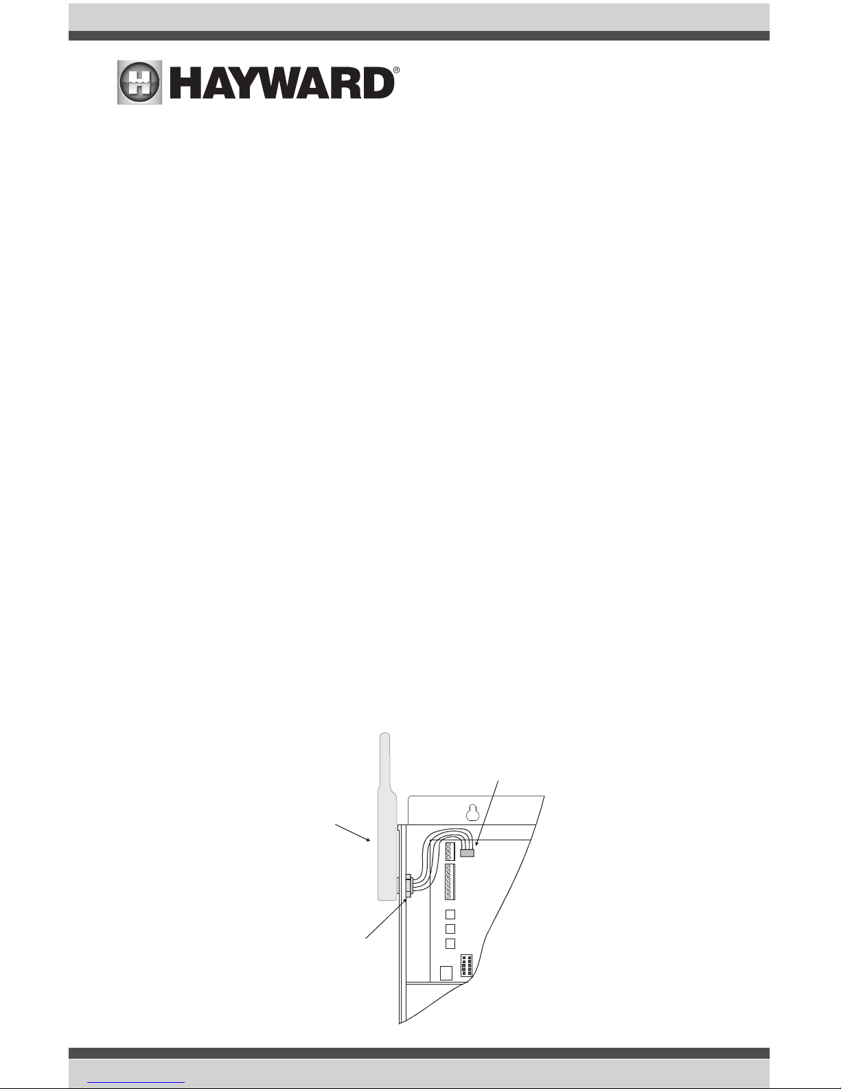
Direct Mounting of the Base Station
Disconnect power and then remove the panel from the Pro Logic or Aqua Logic control unit.
Remove the knock-out on the upper left side of the enclosure and mount the RF Base Station.
Secure the Base Station in place by firmly tightening the nut from inside of the enclosure. Lastly,
plug the pigtail cable into the connector labeled “Wireless Connector” on thePro Logic/ Aqua
Logic main circuit board.
Base Station
(AQL2-BASE-RF)
Tighten nut
Main PCB
Connector for
Base Station
USE ONLY HAYWARD GENUINE REPLACEMENT PARTS
2
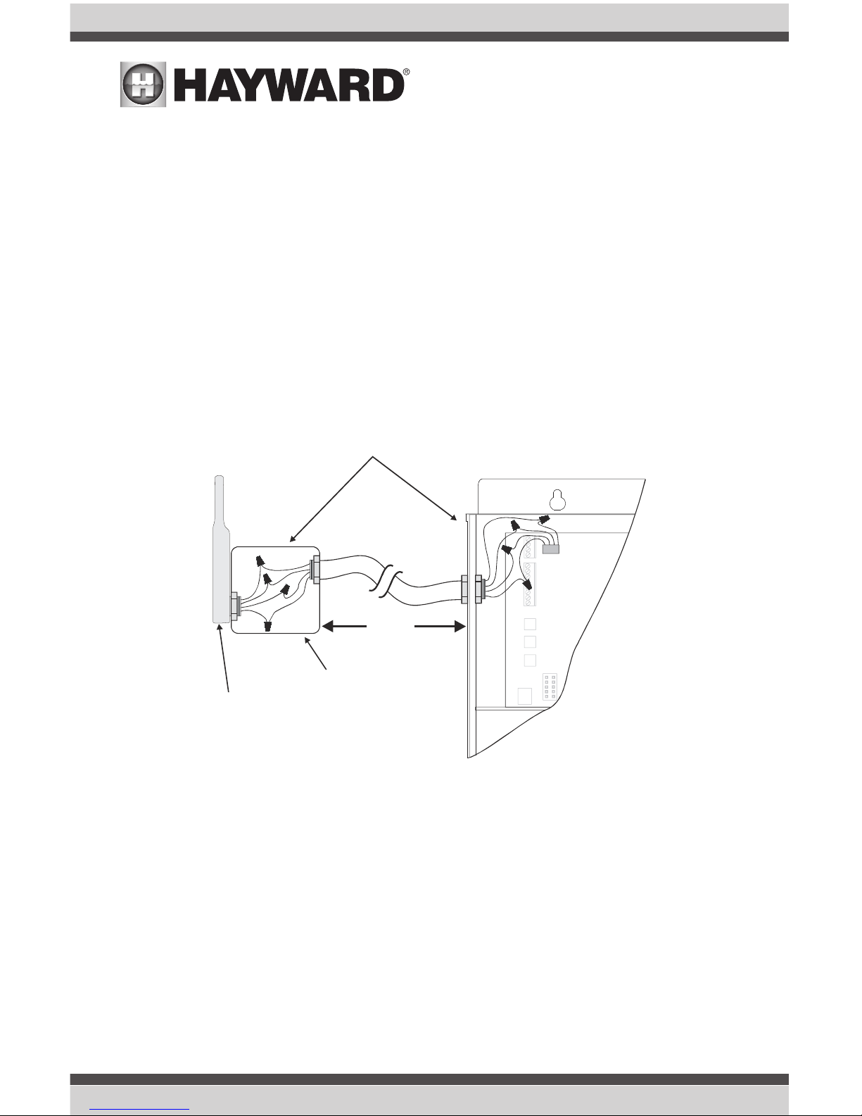
Remote Mounting of the Base Station
The Base Station can be mounted up to 500 feet away from the Pro Logic or Aqua Logic control
unit. This feature is helpful if the main control unit is located a long distance from the pool area
or if there are buildings that may interfere with the radio communication between the Base Station and the remote devices.
1. Mount the Base Station on an standard, outdoor rated electrical box.
2. Cut each of the 4 wires in the Base Station “pigtail” cable and then install the connector half into the “Wireless Connector” on the main printed circuit board (PCB) in the Pro
Logic/Aqua Logic control unit.
3. Use a 4 conductor cable and splice both ends of the cable making sure that the colors
match up correctly.
Operation
Every Base Station is manufactured with a unique ID code. This allows private, secure communication with all of your remote devices while ignoring any signals transmitted by other wireless
devices including any other Pro Logic/Aqua Logic controls in the neighborhood.
IMPORTANT: Before trying to use any remote device, you must “teach” the correct ID code to the
remote device so it knows which Base Station to communicate with. Refer to the Pro Logic/Aqua
Logic Operation Manual or the manual for your remote device for “teaching” instructions.
The Base Station and remote devices are programmed with a sophisticated protocol that automatically switches frequencies if other devices are interfering. In the unlikely event that it can not
find a usable frequency, it may be necessary to change channels. Refer to the Pro Logic/Aqua
Logic Operation Manual for instructions.
Cut 4 wire pigtail on base
receiver and splice in connecting cable
Standard
Electrical Box
Base Receiver
Wireless
Connector
500’
(max)
 Loading...