

Page 1
092520 RevA
R
E
T
T
E
N
K
I
C
CM
C
3101970
Conforms to UL 1081 and
CSA, C22.2 #218.1
US
L
I
D
S
E
T
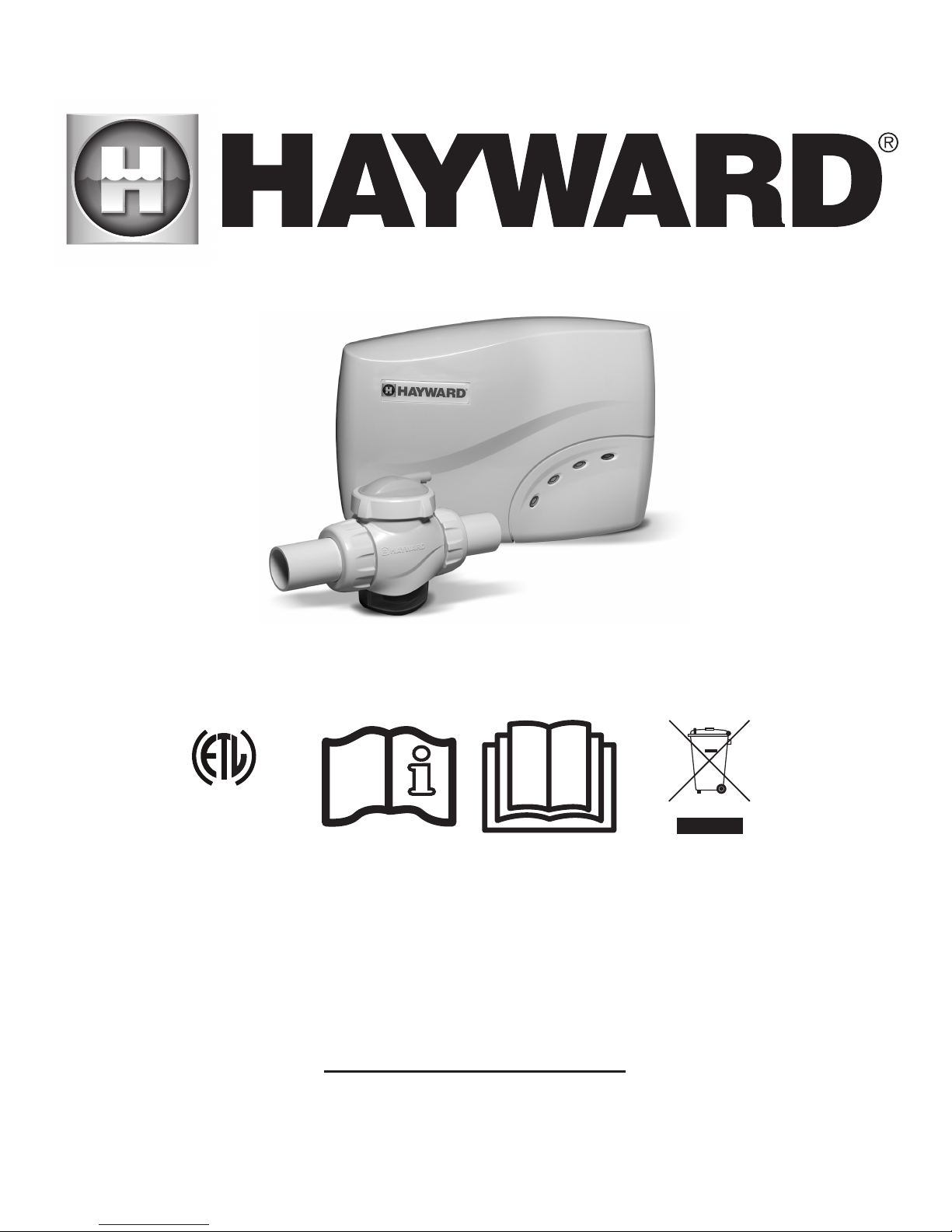
SALT & SWIM™ 3C
SAS-CUL
USER’S GUIDE
SAVE THIS OWNER’S MANUAL
HAYWARD POOL PRODUCTS CANADA, INC.
2880 Plymouth Drive, Oakville, ON, L6H 5R4
855-429-9274 / HAYWARDPOOL.CA
Page 2

WARNING: Electrical Hazard. Failure to follow
instructions can result in serious injury or death.
FOR USE WITH SWIMMING POOLS
• WARNING – Disconnect this product from the main power supply completely before servicing
the swimming pool equipment.
• WARNING – All electrical connections must be done by a qualified electrician according to
local electrical standard.
• WARNING – Be certain the product is only plugged into a protected 120 V outlet that is protected
from short-circuits.
• WARNING – Children should be supervised to ensure that they do not play with the appliance.
Keep ngers and foreign objects away from openings and moving parts.
• WARNING – Make sure that the power supply voltage required by the product corresponds to
that of the distribution network and that the power supply cables matches the power and current of
the product.
• WARNING – Do not bury cord. Locate cord to minimize abuse from lawn mowers, hedge
trimmers, and other equipment.
• WARNING – To reduce the risk of electric shock, do not use extension cord to connect unit to
electric supply; provide a properly located outlet.
• WARNING – Read and follow all instructions in this owner’s manual and on the equipment.
Failure to follow instructions can cause serious injury or death.
This document should be given to the owner of the swimming pool and must be kept by the owner
in a safe place.
• WARNING – This appliance is not intended for use by persons (including children) with
reduced physical, sensory or mental capabilities, or lack of experience and knowledge, unless
they have been given supervision or instruction concerning use of the appliance by a person
responsible for their safety.
• WARNING – Use Only Genuine Hayward Replacement Parts.
• WARNING – If the supply cord is damaged it must be replaced by the manufacturer, service
agent, or similarly qualified persons in order to avoid a hazard.
• WARNING – Do not operate the product if the power cord is damaged. This can cause an
electric shock. A damaged power cord must be replaced by a service agent or a similarly qualified
person immediately in order to avoid a hazard.
USE ONLY HAYWARD GENUINE REPLACEMENT PARTS
Page 2 Salt & Swim™ 3C
Page 3

REGISTRATION
Thank you for choosing Hayward. This manual contains important information regarding the operation
and maintenance of your product. Please retain it for reference.
TO REGISTER YOUR PRODUCT IN OUR DATABASE, GO TO:
www.haywardpool.ca
---------------------------------------------------------------------------------------------------------------------------------------------------------------------------------------------
For Your Records
Record the following information for your convenience:
1) Purchase Date_________________________________________________________
2) Complete Name ________________________________________________________
3) Address ______________________________________________________________
4) Postal code______________________________________________________________
5) Email Address__________________________________________________________
6) Part number______________________Serial number__________________________
7) Pool Dealer____________________________________________________________
8) Address_______________________________________________________________
9) Postal code____________________Country____________________________________
Note
----------------------------------------------------------------------------------------------------------------------------------------------------------------------------------------------
USE ONLY HAYWARD GENUINE REPLACEMENT PARTS
Page 3 Salt & Swim™ 3C
Page 4
GENERAL
The Salt & Swim™ 3C is an automatic chlorine generation system for pool sanitation. The operation requires a low
concentration of salt (sodium chloride) in the pool water. The Salt & Swim 3C automatically sanitizes your pool by converting
the salt into free chlorine which kills bacteria and algae in the water. Chlorine will revert back to sodium chloride after killing
bacteria. These reactions will continuously recycle virtually eliminating the need to add sanitizing chemicals to your pool.
The Salt & Swim 3C can handle the purification needs of most residential swimming pools up to 30,000 gallons (114,000
liters). This unique low cost chlorine generator uses a replaceable electrolytic Cell (SAS-CELL-CUL) that is designed to
produce 91 kg (200 lbs) of 100% available chlorine over its lifetime (cell sold separately).
Part number: SAS-CUL
Note that the actual amount of chlorination required to properly sanitize a pool varies due to bather load, rainfall, temperature,
and the pool’s cleanliness.
NOTE: Before installing this product as part of a saline water purification system in a pool or spa using natural stone for
coping or for immediately adjacent patios/decking, a qualified stone installation specialist should be consulted regarding the
appropriate type, installation, sealant (if any) and maintenance of stone used around a saline pool with electronic chlorine
generator in your particular location and circumstances.
NOTE: The use of dry acid (sodium bisulfate) to adjust pool pH is discouraged especially in arid regions where pool water is
subject to excessive evaporation and is not commonly diluted with fresh water. Dry acid can cause a buildup of by-products
that can damage your chlorinator Cell.
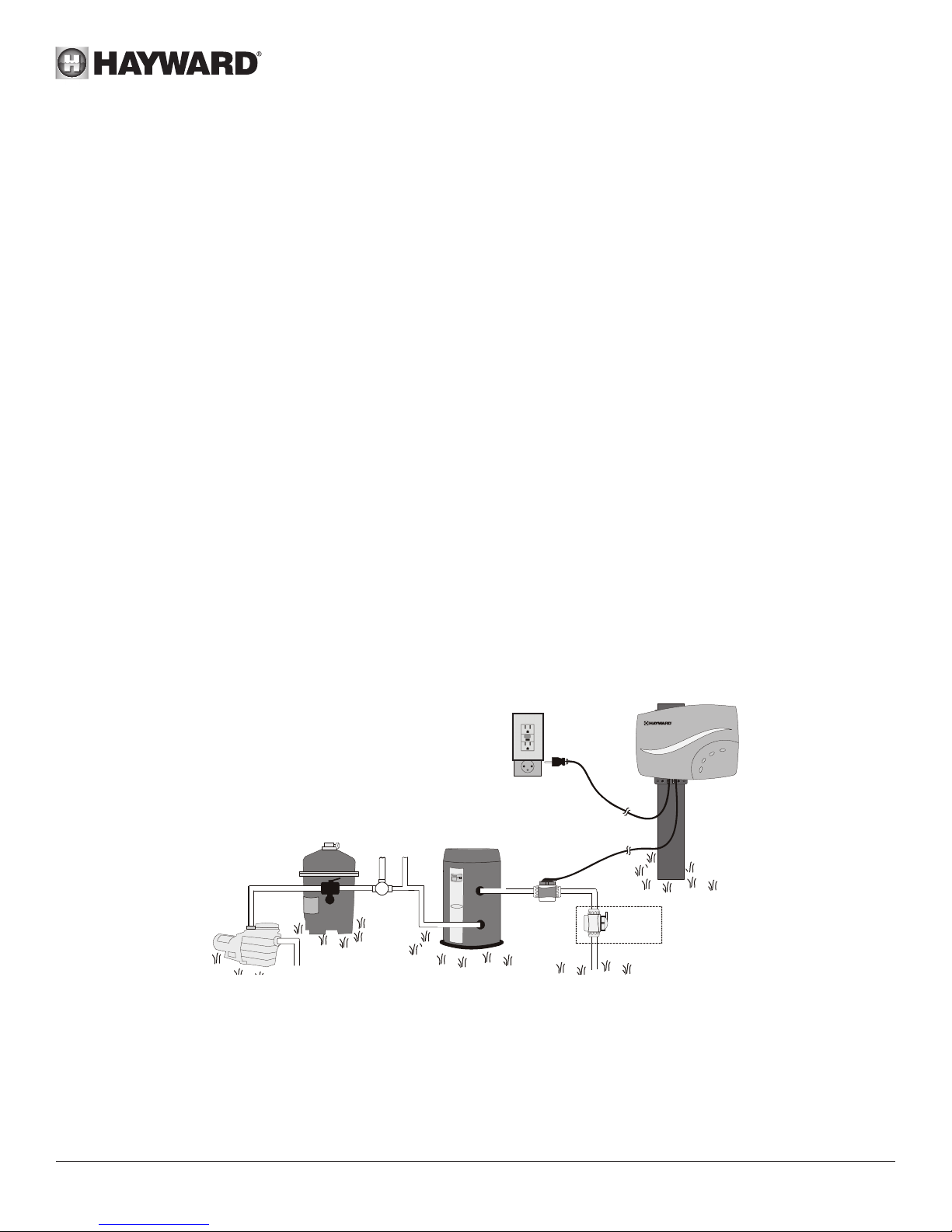
INSTALLATION
Remove power to the pool filter pump before starting this installation. Installation must be performed in accordance with
Local and NEC codes. The Control Box must be mounted a minimum of 3.5 meters (12ft.) horizontal distance (or more, if
local codes require) from the pool, within 2 meters (6.5 ft.) from a protected outlet, and within 4.5 meters (15 ft.) from where
the Cell will be installed. Take care to protect the Cell cap connector pins while handling the Salt & Swim 3C unit during
installation.
Protected 120 V outlet
2 meters
(6.5 ft.)
Filter
pump
Filter Solar
From Pool
System
Heater
Preparing Pool Water
To prepare the pool water for Salt & Swim 3C operation, the pool’s chemistry must be balanced and salt must be added.
This must be done BEFORE activating the Salt & Swim 3C. Some adjustments to your pool chemistry may take several
hours, so start the procedure well before you intend to operate the Salt and Swim 3C.
Cell
Vessel
4.5 meters
To Pool
(15 ft.)
Optional
vertical
installation
Adding Salt: Add salt several hours or, if possible, 1 day prior to operating the Salt & Swim 3C. Take care not to exceed the
recommended salt level. Measure salt 6-8 hours after adding to the pool.
USE ONLY HAYWARD GENUINE REPLACEMENT PARTS
Page 4 Salt & Swim™ 3C
Page 5
NOTE: If the pool does not have new water, add 1 liter of metal remover and 1 liter of non-copper based algaecide to the
pool, per manufacturer’s instructions. This ensures a quick, trouble free transfer to the Salt & Swim 3C system.
Salt & Swim 3C Installation
Follow the step by step instructions located on the Installation Quick Start Guide. Refer to the following sections for more
detailed information.
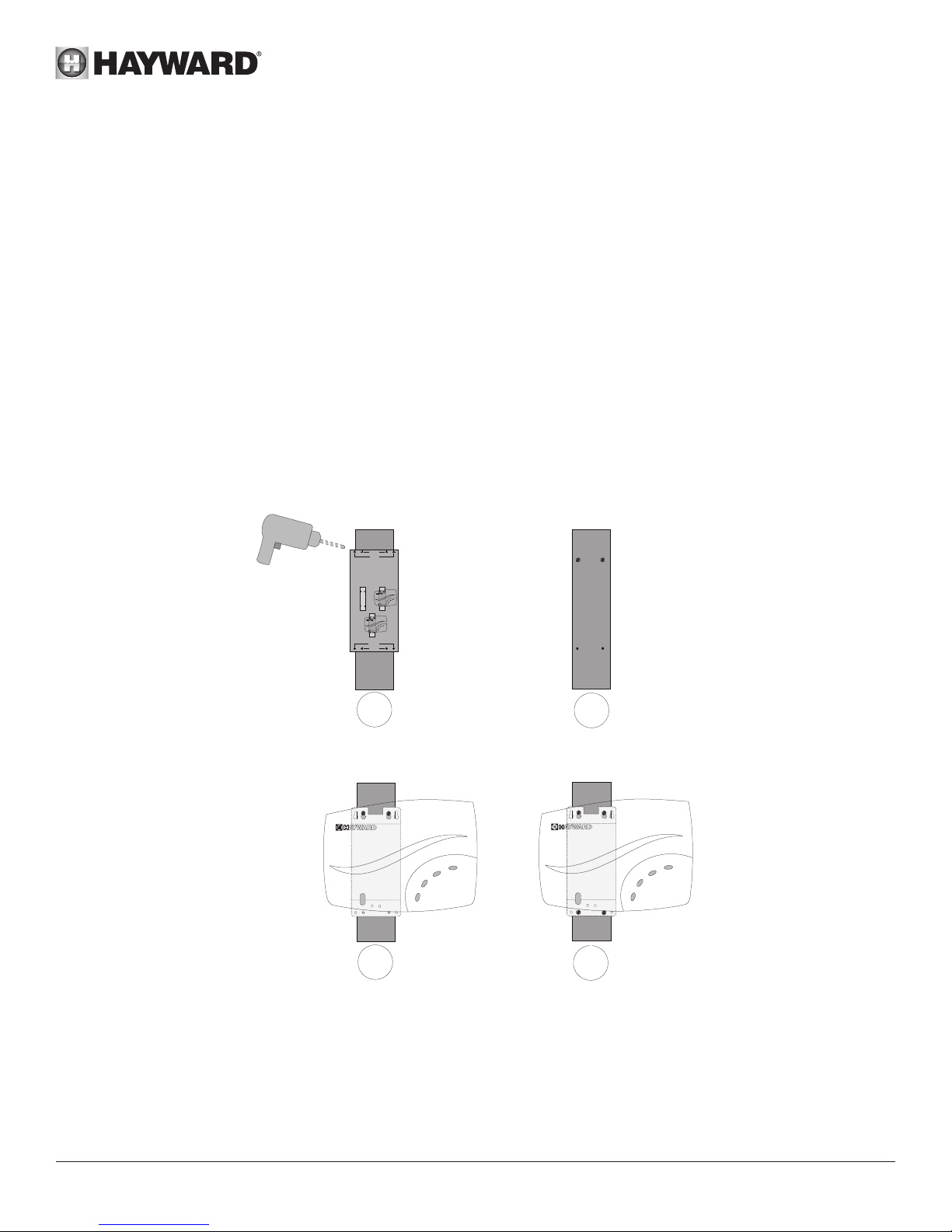
Mounting the Salt & Swim 3C Control Box
The Salt & Swim 3C is contained in a raintight enclosure that is suitable for outdoor mounting. The Control Box must be
mounted a minimum of 3.5 meters (12 ft.) horizontal distance (or more, if local codes require) from the pool, within 2 meters
from a protected outlet, and within 4.5 meters (15 ft.) from where the Cell is installed.
The Control Box is designed to mount vertically on a flat surface with the cables facing downward. Because the enclosure
also acts as a heat sink (disperses heat from inside the box), it is important not to block the four sides of the Control Box.
Do not mount Salt & Swim 3C inside a panel or tightly enclosed area.
Before securing the Control Box to the intended location, make sure that the power cord will reach the protected outlet and
that the Cell cable will reach the location where the Cell Vessel will be installed. Use the included Mounting Template to
position the fasteners to the mounting surface. Refer to the diagram below.
Secure Mounting
Template to desired
mounting location and drill
mounting holes.
Use to mount
on at surface
Use to mount
on post
MOUNTING TEMPLATE
Use the included hardware or your own hardware
(suitable for a 20lb load) to mount the Control Box
to a wall or post within 3 feet of a GFCI outlet,
making sure that the cord will reach. Use this
template to locate and drill fastener holes.
After marking the mounting
surface with this tem plate ,
screw in top fasteners leaving
1/8” space betwe en
Hang Control Box
screw head and surf ace
on fasteners
Screw in bottom fas teners securel y
Use to mount
on at surface
Use to mount
on post
092xxx
1
Hang Control Box
on fasteners
Screw in top
fasteners leaving
3 mm space between
screw head and surface
2
Screw in bottom
fasteners securely.
Plumbing
The Cell Vessel is designed to install in either 50 mm or 63 mm (1½” or 2”) PVC pool plumbing. The Cell Vessel must be
installed on a 25 cm (10 in) run of straight pipe at the end of the return piping just before the water returns to the pool. All pool
equipment should be upstream from the Cell Vessel. It must be located within 4.5 meters (15 ft.) of where the Control Box is
mounted. Also, there must be enough clearance to insert and remove the Cell from the Vessel after the Vessel is installed.
USE ONLY HAYWARD GENUINE REPLACEMENT PARTS
Page 5 Salt & Swim™ 3C
3
4
Page 6
With power removed to the pump and water drained from the pool plumbing, secure the Cutting Template to the location
where the Cell Vessel will be installed. Note that the Cutting Template is the same width as the Cell Vessel. The entire
Cutting Template must fit on the pipe otherwise the Cell Vessel will not fit. With the Cutting Template secure on the pipe,
mark all 10 cutouts on to the pipe using a waterproof permanent marker.
Permanent
Marker
Mark all
10 cutouts
Filter
pump
Filter Solar
From Pool
System
Heater
Cutting
Template
To Pool
The Cutting Template is the same length as
the installed Vessel. Make sure that the entire
Cutting Template Fits at the desired location.
Secure the Template and mark all of the
cutouts.
Remove the Template, cut the pipe and install the Nut Assemblies as shown below. Use the included 63 mm (2 in) Nut
Assembly for 63 mm (2 in) pipe and 50 mm (1.5 in) Nut Assembly for 50 mm (1.5 in) pipe. Place Nut Assembly on each side
of the cut pipe (threads face in). Be sure to place the Nut, Compression Ring and Collar on the pipe as shown in the diagram.
Cutting Template
Mark Pipe
Cut Pipe and
Clean Shavings
USE ONLY HAYWARD GENUINE REPLACEMENT PARTS
Page 6 Salt & Swim™ 3C
Slide Nuts
on Pipe
Slide Compression
Rings over marks
Slide Collars
on pipe
Page 7
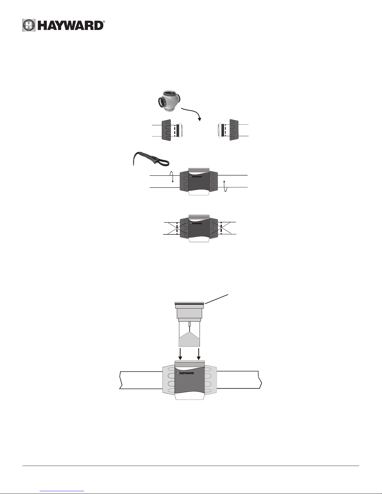
Position the Vessel in a manner where the Cell can be easily inserted and removed. Secure the Vessel to the cut pipe by
tightening the Nuts as shown below. Hand tighten the Nuts to stop, then continue 1/4 turn more using the included strap
wrench. If the Inspection marks can be seen, the pipe has not been inserted far enough into the Cell Vessel.
Verify that both Cell
Vessel gaskets are in place
Insert Cell
6
Vessel and
hand tighten
Nuts
Use the included strap wrench
to tighten an additional 1/4 turn
7
IMPORTANT:
Inspection
Marks should
not be visible
If so, loosen
Nuts and slide
the pipes further
into the Cell
Vessel and
re-tighten
Remove the foam protector from the Cell. Verify that the O-Ring is attached before inserting the Cell into the Cell Vessel.
O-Ring
USE ONLY HAYWARD GENUINE REPLACEMENT PARTS
Page 7 Salt & Swim™ 3C
Page 8
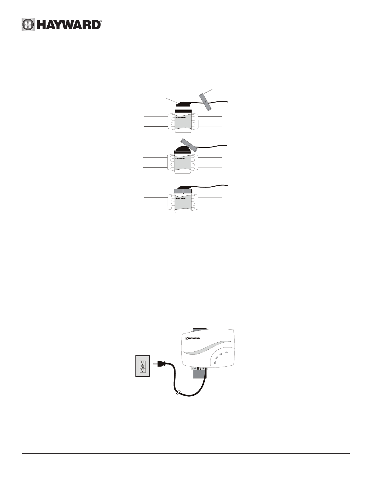
Connect and Fasten Cell Cap
Slip the Cell Cap through the Retaining Nut as shown below. Plug the Cell Cap into the Cell and secure with the Retaining
Nut. Run pump for 5 minutes and check for leaks.
Retaining Nut
Cell Cap
Flow Switch Calibration Procedure
IMPORTANT: Before going any further, the pool water must be balanced and salt must be added to your pool. If this has
not already been done, refer to the “Water Chemistry” section of this manual for information on how to prepare your pool
water for Salt & Swim 3C operation.
At start-up, or when a new Cell is installed, the Salt & Swim 3C will run a Flow Switch Calibration procedure to ensure that
the Cell’s flow switch is properly initialized. This will occur just once when a new Cell is installed. After the flow switch is
initialized, the Salt & Swim 3C will not perform this procedure again until the Cell is replaced. The Flow Switch Calibration
procedure will require the user to cycle the pump on and off. Follow the instructions below:
1. Turn the filter pump OFF.
2. Plug the Salt & Swim’s linecord into a protected outlet. Follow Local and National codes.
120 V
Protected
outlet
After being powered on for the first time, the Salt & Swim 3C will run a diagnostic routine which can take up to 30
seconds. During this time, various LEDs will turn on and off. When finished, the Salt & Swim 3C will display a blinking
INADEQUATE WATER FLOW LED and a solid STANDING BY LED. Keep the Salt & Swim 3C powered for the remainder
of this procedure and go to Step 3.
USE ONLY HAYWARD GENUINE REPLACEMENT PARTS
Page 8 Salt & Swim™ 3C
Page 9
3. Turn the filter pump ON. Make sure that full flow is achieved (no air in the system) and run the pump for at least 15
seconds.
4. Turn the filter pump OFF.
5. The Salt & Swim 3C should now display a solid INADEQUATE WATER FLOW and a solid STANDING BY LED. The Flow
Switch Calibration procedure is complete. You can now turn on your filter pump and begin normal operation.
If the INADEQUATE WATER FLOW LED is still blinking after performing this procedure, refer to the Troubleshooting section
of this manual.
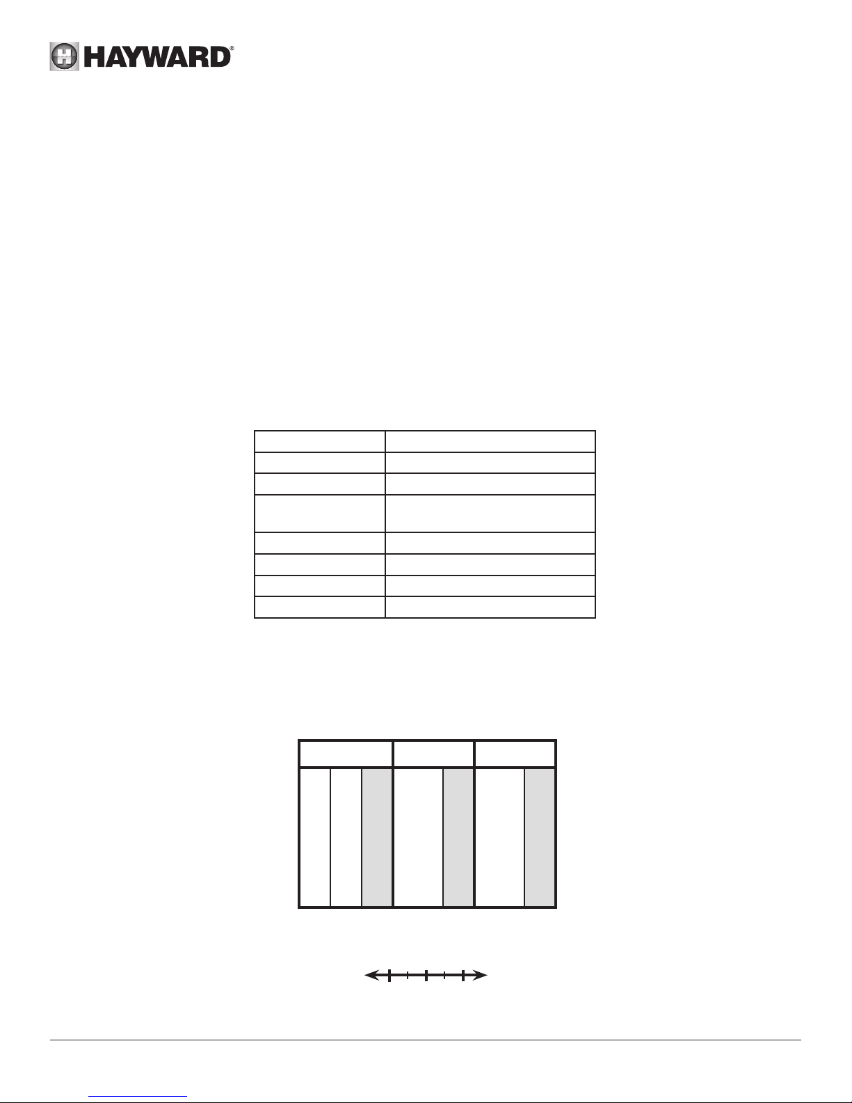
Water Chemistry
The table below summarizes the levels that are recommended by Hayward. The only special requirements for the Salt &
Swim 3C are the salt level and stabilizer. It is important to maintain these levels in order to prevent corrosion or scaling and
to ensure maximum enjoyment of the pool. Test your water periodically. Your authorized Salt & Swim 3C dealer or most pool
stores can provide you with the chemicals and procedures to adjust the water chemistry. Be sure to tell the pool store that
you are using a Salt & Swim 3C chlorine generator.
CHEMICAL IDEAL LEVELS
Salt 2.7 to 3.4 g/l
Free Chlorine 1.0 to 3.0 ppm
pH 7.2 to 7.8
Cyanuric Acid
(Stabilizer)
20 to 30 ppm (25 ppm best)
Add stabilizer only if necessary
Total Alkalinity 80 to 120 ppm
Calcium Hardness 200 to 300 ppm
Metals 0 ppm
Saturation Index -.2 to .2 (0 best)
Saturation index
The saturation index (Si) relates to the calcium and alkalinity in the water and is an indicator of the pool water “balance”.
Your water is properly balanced if the Si is 0 ±.2. If the Si is below -0.2, the water is corrosive and plaster pool walls will
be dissolved into the water. If the Si is above +0.2, scaling and staining will occur. Use the chart below to determine the
saturation index.
Si = pH + Ti + Ci + Ai - 12.1
0.3
0.4
0.5
0.6
0.7
0.8
0.9
- 0.2
Calcium
Hardness
75
100
125
150
200
250
300
400
600
800
OK
°C °F Ti
53
12
60
16
66
19
76
24
84
29
94
34
100
39
How to use: Measure pool pH, temperature, calcium hardness, and
total alkalinity. Use the chart above to determine Ti, Ci and Ai into the
above equation. If Si equals 0.2 or more, scaling and staining may
occur. If Si equals -0.2 or less corrosion or irritation may occur.
CORROSIVE
USE ONLY HAYWARD GENUINE REPLACEMENT PARTS
Page 9 Salt & Swim™ 3C
Ci
1.5
1.6
1.7
1.8
1.9
2.0
2.1
2.2
2.4
2.5
0.20
{
Total
Alkalinity
75
100
125
150
200
250
300
400
600
800
SCALING
Ai
1.9
2.0
2.1
2.2
2.3
2.4
2.5
2.6
2.8
2.9
Page 10
Salt Level
Use the chart on page 10 to determine how much salt in Kgs need to be added to reach the recommended levels. Use
the equations below if pool size is unknown.
Gallons
(pool size in feet)
Rectangular
Round
Oval
The ideal salt level is between 2.7 g/l (2700 ppm) - 3.4 g/l (3400 ppm) with 3.2 g/l (3200 ppm) being ideal. If the level is
low, determine the number of M3 in the pool and add salt according to the chart on page 10. A low salt level will reduce
the efficiency of the Salt & Swim 3C and result in low chlorine production. A high salt level can cause the Salt & Swim 3C
to shutdown and may begin to give a salty taste to your pool (generally, the salt will begin to be tasted at a level of about
3.5g/l [3500 ppm] - 4.0 g/l [4000 ppm]). The salt in your pool is constantly recycled and the loss of salt throughout the
swimming season should be small. This loss is due primarily to the addition of water because of splashing, backwashing,
or draining (because of rain). Salt is not lost due to evaporation.
Type of Salt to Use
It is important to use only sodium chloride (NaCl) salt that is greater than 99% pure. This is common food quality or water
softener salt and is usually available in 25 kg (55 lbs) bags. It is also acceptable to use water conditioning salt pellets,
however, it will take longer for them to dissolve. Do not use rock salt, salt with yellow prussiate of soda, salt with anticaking additives, or iodized salt.
How to Add or Remove Salt
For new plaster pools, wait 10-30 days (check with you local pool professional) before adding salt to allow the plaster to
cure. Turn the circulating pump on and add salt directly into the pool. Brush the salt around to speed up the dissolving
process--do not allow salt to pile up on the bottom of the pool. Run the filter pump for 24 hours with the suction coming
from the main drain (use pool vac if there is no main drain) to allow the salt to evenly disperse throughout the pool.
Length x Width x
Average Depth x 7.5
Diameter x Diameter x
Average Depth x 5.9
Length x Width x
Average Depth x 6.7
Average Depth x 1000
Diameter x Diameter x
Average Depth x 785
Average Depth x 893
Liters
(pool size in meters)
Length x Width x
Length x Width x
The only way to lower the salt concentration is to partially drain the pool and refill with fresh water.
Always check stabilizer (cyanuric acid), when checking salt. These levels will most likely decline together. Use the chart
on page 10 to determine how much stabilizer must be added to raise the level to 25 ppm maximum (Use stabilizer only if
necessary).
USE ONLY HAYWARD GENUINE REPLACEMENT PARTS
Page 10 Salt & Swim™ 3C
Page 11

WEIGHT OF STABILIZER (CYANURIC ACID in Kg) NEEDED FOR 25 PPM
Current
Stabilizer
level in ppm
0 ppm 0.75 0.94 1.13 1.34 1.53 1.69 1.91 2.09 2.28 2.47 2.66 2.84 3.03 3.22 3.41 3.59 3.75
10 ppm 0.45 0.56 0.68 0.81 0.92 1.01 1.14 1.26 1.37 1.48 1.59 1.71 1.82 1.93 2.04 2.16 2.25
20 ppm 0.15 0.19 0.23 0.27 0.31 0.34 0.38 0.42 0.46 0.49 0.53 0.57 0.61 0.64 0.68 0.72 0.75
25 ppm 0 0 0 0 0 0 0 0 0 0 0 0 0 0 0 0 0
30
(8000)
37.5
(9,900)45(11,900)
52.5
(13,900)60(15,850)
67.5
(17,800)75(19,800)
M3 (gallons) of Pool water
82.5
(21,800)90(23,700)
97.5
(25,800)
105
(27,700)
112.5
(29,700)
120
(31,700)
127.5
(33,700)
135
(35,700)
USE ONLY HAYWARD GENUINE REPLACEMENT PARTS
Page 11 Salt & Swim™ 3C
142.5
(37,600)
150
(39,600)
Page 12

Controls
The main controls and indicators are shown below.
CELL LIFE LOW: Illuminates when cell has reached the end of its expected life.
PROBLEM DETECTED: When this LED indicator is illuminated, there is a problem with
the unit. Refer to the Troubleshooting section of this manual.
STANDING BY: Illuminates when unit is waiting for the filter pump to turn on or is in-between
generating cycles as part of normal operation to maintain selected daily chlorine output.
GENERATING CHLORINE: Illuminates when unit is actively generating chlorine.
SUPER CHLORINATING: Illuminates when unit is super chlorinating.
INADEQUATE WATER FLOW: Illuminates when there is no flow or low flow through the cell.
The pool filter pump could be in its “off” cycle. If this is not the case, refer to the Troubleshooting
section in this manual. Blinks when performing the Flow Switch Calibration procedure.
DAILY CHLORINE OUTPUT: Press ( + ) and ( - ) to increase or decrease the chlorine
generation. The DAILY CHLORINE OUTPUT LEDs above these buttons will indicate the
relative amount of chlorine being generated.
SUPER CHLORINATE: When you have an abnormally high bather load, a large amount
of rain, a cloudy water condition, or any other condition which requires a large amount of
purification to be introduced, press the “S” button. This electronically “super chlorinates”
(boosts chlorine generation output) the water for 24 hours (filter pump must be on during
this time). To cancel super chlorinating, press the “S” button again.
USE ONLY HAYWARD GENUINE REPLACEMENT PARTS
Page 12 Salt & Swim™ 3C
Page 13

OPERATION
The Salt & Swim 3C does not have an ON/OFF switch. The unit is designed to be plugged into a protected outlet at all
times. There should be no need to remove power from the Salt & Swim 3C unless pool components are being serviced or
the pool will be closed.
When power is first applied to the Salt & Swim 3C, an initialization routine will run for approximately 30 seconds. During
this time, various LEDs will illuminate. This is perfectly normal and does not require any input from the user. When the
routine is finished, the Salt and & Swim 3C will begin normal operation.
If the water chemical levels are in the recommended range, there are three factors that you can control which directly
contribute to the amount of chlorine the Salt & Swim 3C will generate:
1. filter time each day (hours)
2. the DAILY CHLORINE OUTPUT setting
3. the amount of salt in the pool
The filter pump timer should be set so that all of the water in the pool passes through the filter at least once each day. For
pools with high chlorine demand, the timer may have to be set longer to generate enough chlorine.
Daily Chlorine Output Setting
You can adjust the amount of chlorine that is generated using the “+” and “-” button on the Salt & Swim 3C unit. The
DAILY CHLORINE OUTPUT LEDs will display the current setting. Push “+” to increase and “-” to decrease the current
setting. Each DAILY CHLORINE OUTPUT LED represents 6 minutes of chlorine generation out of 1 hour. For example,
if 5 LEDs are illuminated, the Salt & Swim 3C unit will generate chlorine for 5 x 6 = 30 minutes out of every hour of
operation. During this time, the GENERATING CHLORINE LED will be lit. The unit will be idle for the remaining 30
minutes at which time the GENERATING CHLORINE LED will turn off and the STANDING BY LED will illuminate.
To find the optimum setting, start the operation with 5 DAILY CHLORINE OUTPUT LEDs illuminated. Test the chlorine
level every few days and adjust up or down accordingly. It usually takes 2-3 adjustments to find the ideal setting for
your pool and after that, it should only take minor, infrequent adjustments. Because the chlorine demand of the pool
increases with temperature, most people find they have to adjust up at the peak of the summer and down during colder
periods. The Salt & Swim 3C automatically scales back to 12 minutes of output per hour (if set higher than 12 minutes)
when the pool water is 10ºC (50ºF) - 15°C (59ºF). This protects the unit as well as prevents possible over-chlorination.
The Salt & Swim 3C stops generating when the pool water temperature drops below 10°C (50ºF). This is usually not a
problem because bacteria and algae stop growing at this temperature. You can override these automatic low temperature
operations by switching to SUPER CHLORINATE for a day.
NOTE: After the ideal DAILY CHLORINE OUTPUT setting has been found, you may need to raise the setting when the
pool water temperature increases significantly, when there is higher than normal bather load or when the Salt & Swim 3C
Cell ages. You may need to lower the setting when the pool water temperature decreases significantly or there are long
periods of inactivity.
Prevent over-chlorination during cold weather: Check chlorine levels periodically. Most pools require less chlorine
during cold weather and the DAILY CHLORINE OUTPUT should be lowered accordingly.
Maintaining the Salt & Swim 3C System
The replaceable Cell uses the same electronic self cleaning technology as the popular Hayward Turbo Cell. In most
cases this self cleaning action will keep the Cell working at optimum efficiency. In areas where water is hard (high mineral
content) and in pools where the water chemistry has been allowed to get “out of balance,” the Cell may require periodic
cleaning.
Servicing and Cleaning the Salt & Swim 3C Cell
Unplug the Salt & Swim 3C from the protected outlet before attempting to remove the electrolytic Cell. Once removed,
look inside the Cell and inspect for scale formation (light colored crusty or flaky deposits) on the plates and for any debris
which has passed through the filter and caught on the plates. If no deposits are visible, reinstall. If deposits are seen,
use a high pressure garden hose and try to flush the scale off. If this is not successful, use a plastic or wood tool (do
not use metal as this will scratch the coating off the plates) and scrape deposits off of plates. Note that a buildup on the
USE ONLY HAYWARD GENUINE REPLACEMENT PARTS
Page 13 Salt & Swim™ 3C
Page 14

Cell indicates that there is an unusually high calcium level in the pool (old pool water is usually the cause). If this is not
corrected, you may have to periodically clean the Cell. The simplest way to avoid this is to bring the pool chemistry to the
recommended levels as specified.
Mild Acid Washing: Use only in severe cases where flushing and scraping will not remove the majority of deposits.
To acid wash, unplug the Salt & Swim 3C unit from the protected outlet and unplug the Cell cord from the replaceable
Cell. Remove the Cell from the Vessel by unscrewing the Retaining Nut and gently pulling the Cell from the Vessel. In
a clean plastic container, mix a solution of water to phosphoric or citric acid. ALWAYS ADD ACID TO WATER - NEVER
ADD WATER TO ACID. Be sure to wear rubber gloves and appropriate eye protection. The level of the solution in the
container should just reach the top of the Cell so that the cylindrical electronics compartment is not submerged. The Cell
should soak for a few minutes and then rinse with a high pressure garden hose. If any deposits are still visible, repeat
soaking and rinsing. Replace Cell and inspect again periodically.
Winterizing
The Salt & Swim 3C replaceable Cell will be damaged by freezing water just as your pool plumbing would. In areas of the
country which experience severe or extended periods of freezing temperatures, be sure to drain all water from the pump,
filter, and supply and return lines before any freezing conditions occur. The Control Box and plumbed in Cell Vessel are
capable of withstanding any winter weather and should not be removed.
Spring Start-up
DO NOT turn the Salt & Swim 3C on until the pool water chemistry has been brought to the proper levels. Refer to the
“Water Chemistry” section of this manual for information on how to prepare your pool water for Salt & Swim 3C operation.
TROUBLESHOOTING
Common Problems and Solutions
The Salt & Swim 3C’s various LEDs show the operation status as well as alert the user to any problems that may have
occurred. Some indications may require a combination of LEDs to illuminate. To aid in interpreting these indications,
Hayward has created an interactive tool located at Services on our web site www.haywardpool.ca. Use this tool and the
information below to identify and correct problems that may arise.
1. Possible causes of little or no free chlorine residual
- DAILY CHLORINE OUTPUT adjustment setting is too low
- Low stabilizer (Cyanuric Acid)
- Filter pump time too short (8 hours for average size pools, more for large pools)
- Salt level too low (below 2.4 g/l [2400 ppm])
- Salt level too high
- Very warm pools increase chlorine demand--increase Output %, or filter run time
- Cold water below 10°C (50ºF) causes Salt & Swim to stop generating
- Cold water between 10°C (50ºF) - 15°C (59ºF) causes Salt & Swim 3C to reduce output regardless of DAILY CHLORINE OUTPUT
setting
- Excessive scaling on Cell.
- High level of Nitrogen in pool water.
- “Yellow Out” or similar treatment recently used. Some yellow algae treatments will use chlorine at a very high rate and deplete
the residual free chlorine. Manually shock the pool if indicated in the directions on the algae treatment. It still may be a matter of days
before the pool returns to “normal” and chlorine tests will show the desired 1 - 3ppm free chlorine reading.
2. LEDs not on
Depending on current conditions, there should always be at least one LED illuminated when the Salt & Swim 3C is powered. If no
LEDs are on, check to make sure that the linecord is plugged in and that the protected outlet is powered. If no power is detected, the
protection may have to be reset.
3. STANDING BY LED blinking
The Salt & Swim 3C has shut down because the temperature of the pool water is too high (49°C/120ºF) or too low (10°C/50ºF). The
system will not resume operation until the water temperature returns to normal. Note: This condition can sometimes happen if the pool
temperature is already high and the heater is running. The temperature coming out of the heater and into the Cell could possibly be
high enough to shut down the Salt & Swim 3C.
USE ONLY HAYWARD GENUINE REPLACEMENT PARTS
Page 14 Salt & Swim™ 3C
Page 15

4. INADEQUATE WATER FLOW LED illuminated
The Salt & Swim 3C has sensed a low flow or no flow condition and has stopped generating chlorine.
- Verify that the filter pump is running and there are no obstructions or restrictions in the pool plumbing.
- Backwash the pool filter.
- Increase the speed of your variable speed pump
If the condition persists, remove the Cell from the Vessel and check that the flow switch is free to move in both directions.
Refer to the diagram below.
5. CELL LIFE LOW LED illuminated
The Cell has reached the end of its life. Replace as soon as possible
6. PROBLEM DETECTED LED illuminated AND a DAILY CHLORINE OUTPUT LED is blinking
The Salt & Swim 3C may display an error by illuminating the PROBLEM DETECTED LED and blinking one of the DAILY
CHLORINE OUTPUT LEDs. There are ten DAILY CHLORINE OUTPUT LEDs that each indicate a different error.
These LEDs are labeled with a number on the diagram below. Refer to the table for their corresponding errors.
7. PROBLEM DETECTED LED illuminated AND MAX LED blinking
There is a communication error with the Cell. Check that the Cell cap is properly plugged in and that the wire to the
Control Box is not cut or damaged.
8. PROBLEM DETECTED LED illuminated AND MIN LED blinking
- The salt level may be too low. Adjust salt to recommended levels.
- Remove and inspect the Cell for scale. If the Cell is scaled, follow the directions on “Servicing and Cleaning the
Salt & Swim 3C Cell” chapter.
9. PROBLEM DETECTED LED illuminated AND 20% LED blinking
Salt level is too high. Test the salt level and adjust to the recommended levels.
USE ONLY HAYWARD GENUINE REPLACEMENT PARTS
Page 15 Salt & Swim™ 3C
Page 16

Limited Warranty
All HAYWARD products are covered for manufacturing defects or material defects for a warranty period of 2 years
as of date of purchases. Any warranty claim should be accompanied by evidence of purchase, indicating date of
purchase. We would therefore advise you to keep your invoice.
The HAYWARD warranty is limited to repair or replacement, as chosen by HAYWARD, of the faulty products, provided
that they have been subjected to normal use, in compliance with the guidelines given in their user guides, provided that
the products have not been altered in any way, and provided that they have been used exclusively with HAYWARD
parts and components. The warranty does not cover damage due to frost and to chemicals. Any other costs (transport,
labour, etc.) are excluded from the warranty.
HAYWARD may not be held liable for any direct or indirect damage resulting from incorrect installation, incorrect
connection, or incorrect operation of a product.
In order to claim on a warranty and in order to request repair or replacement of an article, please ask your dealer. No
equipment returned to our factory will be accepted without our prior written approval.
Wearing parts are not covered by the warranty. Wear parts are: gasket and plate coating of cell.
Control Box, SAS-CUL - 3 year limited warranty, parts only
Cell, SAS-CELL-CUL - 1 year limited warranty
USE ONLY HAYWARD GENUINE REPLACEMENT PARTS
Page 16 Salt & Swim™ 3C
Page 17

Hayward is a registered trademark of Hayward Industries, Inc.
© 2011 Hayward Industries, Inc.
Page 18

092520 RevA
R
E
T
T
E
N
K
I
C
CM
C
3101970
Conforms to UL 1081 and
CSA, C22.2 #218.1
US
L
I
D
S
E
T
SALT & SWIM™ 3C
SAS-CUL
GUIDE DE L’UTILSATEUR
CONSERVEZ CE MANUEL D’UTILISATION
HAYWARD POOL PRODUCTS CANADA, INC.
2880 Plymouth Drive, Oakville, ON, L6H 5R4
855-429-9274 / HAYWARDPOOL.CA
Page 19

AVERTISSEMENT : Risque électrique.
Le non-respect de ces instructions peut entraîner
de graves blessures voire la mort.
L’APPAREIL EST DESTINÉ À UNE UTILISATIO N EN PISCINE
• AVERTISSEMENT – Débrancher l’appareil avant de procéder à l’entretien du matériel dans la
piscine.
• AVERTISSEMENT – Tous les raccordements électriques doivent être effectués par un
électricien professionnel agréé qualifié et selon les normes en vigueur dans le pays d’installation.
• WARNING – Soyez certain que le produit soit raccordé dans une prise 120VAC qui est protégé des
cout-circuit.
• AVERTISSEMENT– Cet appareil n’est pas un jouet et doit être conservé hors de portée des
enfants. Gardez vos mains, et tout objet étranger, loin des ouvertures et des parties mobiles.
• AVERTISSEMENT – Vérifier que la tension d’alimentation requise par le produit correspond
à celle du réseau de distribution et que les câbles d’alimentation conviennent pour l’alimentation en
courant du produit.
• AVERTISSEMENT – Ne pas enterrer le cordon. Placer le cordon de manière qu’il ne soit pas
endommagé par les tondeuses à gazon, les taille-haies et autres outils.
• AVERTISSEMENT – Pour réduire le risque de choc électrique, ne pas utiliser de rallonge pour
brancher l’appareil sur le secteur. Utiliser une prise murale.
• AVERTISSEMENT – Lire attentivement et respecter les instructions de ce manuel et celles
figurant sur l’appareil. Le non respect de ces instructions peut être à l’origine de blessures graves
ou entrainer la mort. Le présent document sera remis à l’utilisateur de la piscine, qui devra le
conserver pour s’y reporter le cas échéant.
• AVERTISSEMENT – Ne pas laisser cet appareil à la portée des enfants ni à celle des
personnes dont les capacités physiques, sensorielles ou mentales sont réduites, ou manquant
d’expérience et de connaissances, sauf sous le contrôle d’une personne responsable de leur
sécurité.
• AVERTISSEMENT – N’utiliser que des pièces d’origine Hayward.
• AVERTISSEMENT – Si le cordon d’alimentation est endommagé, il doit être remplacé par le
fabricant, son service après vente ou des personnes de qualification similaire, afin d’éviter un danger.
• AVERTISSEMENT – L’appareil ne doit pas être utilisé si le cordon d’alimentation est
endommagé. Un choc électrique pourrait se produire. Un cordon d’alimentation endommagé doit
être remplacé par le service après vente ou des personnes de qualification similaire, afin d’éviter un
danger.
N’UTILISEZ QUE DES PIÈCES DÉTACHÉES D’ORIGINE HAYWARD
Page 19 Salt & Swim™ 3C
Page 20

ENREGISTREMENT
Merci d’avoir choisi Hayward. Ce manuel contient des informations importantes relatives au
fonctionnement et à l’entretien de votre produit. Le conserver pour vous y reportez ultérieurement.
POUR ENREGISTRER VOTRE PRODUIT SUR NOTRE BASE DE DONNEES,
ALLEZ SUR :
www.haywardpool.ca
---------------------------------------------------------------------------------------------------------------------------------------------------------------------------------------------
Pour votre information
Enregistrer les informations suivantes pour référence ultérieure, le cas échéant :
1) Date d’Achat_________________________________________________________
2) Nom Complet ________________________________________________________
3) Addresse ______________________________________________________________
4) Code postal______________________________________________________________
5) Adresse Email__________________________________________________________
6) Numéro de la pièce______________________Numéro de Série__________________________
7) Vendeur de la Piscine____________________________________________________________
8) Adresse_______________________________________________________________
9) Code postal____________________Pays____________________________________
Note
----------------------------------------------------------------------------------------------------------------------------------------------------------------------------------------------
N’UTILISEZ QUE DES PIÈCES DÉTACHÉES D’ORIGINE HAYWARD
Page 20 Salt & Swim™ 3C
Page 21

GÉNÉRALITÉS
Le Salt & Swim 3C est un système de production automatique de chlore pour l’assainissement des piscines jusqu’à 30 000
gallons (114 000 litres). Pour fonctionner, le chlorateur requiert une faible concentration de sel (chlorure de sodium) dans
l’eau de la piscine. Le Salt & Swim 3C désinfecte automatiquement votre piscine en convertissant le sel en chlore libre, qui
tue les bactéries et les algues contenues dans l’eau. Le chlore se reconvertit en chlorure de sodium après avoir détruit les
bactéries. Le recyclage permanent de ces réactions évite d’ajouter des produits chimiques d’assainissement dans votre
piscine. Cet unique et abordable générateur de chlore fonctionne à l’aide d’une cellule electrolytique remplaçable. Cette
cellule (SAS-CELL-CUL) produit 91kg (200lbs) de chlore 100% pur pendant sa durée de vie (Cellule vendue séparément).
Numéro de la pièce : SAS-CUL
La quantité nécessaire de chlore pour désinfecter correctement une piscine varie en fonction du nombre de baigneurs, des
précipitations, de la température, et de la propreté de celle-ci.
NOTE : Avant d’installer ce produit dans le système de purification d’eau saline d’une piscine ou d’un spa, dont la terrasse
ou le patio adjacent est constitué de pierres naturelles, consulter un installateur qualifié, qui vous conseillera sur le type,
l’installation, l’étanchéisation (s’il y a lieu) et l’entretien des pierres posées autour d’une piscine à eau saline, équipée d’un
générateur de chlore électronique, selon le lieu ou les circonstances d’implantation de la piscine.
NOTE : L’utilisation d’acide sec (bisulfite de sodium) pour ajuster le pH de la piscine est déconseillée, en particulier dans
les régions arides où l’eau de la piscine est exposée à une évaporation importante et n’est pas couramment diluée avec de
l’eau fraiche. L’acide sec peut provoquer une augmentation de sous-produits qui risquent d’endommager votre chlorateur.
INSTALLATION
Débrancher la pompe filtration de la piscine avant de commencer l’installation. L’installation doit être réalisée conformément
aux directives Locales et NEC. Le Boitier de Commande doit être monté à une distance horizontale minimum de 3,5 mètres
(12 pieds) (voire plus, si la législation locale l’exige) de la piscine, à moins de 2 mètres (6.5 pieds) d’une prise protégée, et
à moins de 4,5 mètres (15 pieds) de l’emplacement prévu pour la Cellule. Au cours de l’installation, prendre soin de protéger
les broches du connecteur sur le capuchon de la Cellule pendant les manipulations du Salt & Swim 3C.
Prise protégée 120 V
2 mètres
(6.5 pieds)
Pompe
de
ltration
Préparation de l’eau de la Piscine
Filter
A partir de
la piscine
Systeme
Solaire
Chauffe-eau
Boîtier de
la Cellule
4.5 mètres
(15 pieds)
Vers la
piscine
Installation
verticale en
option
Pour préparer l’eau de la piscine au fonctionnement du Salt & Swim 3C, la composition chimique de celle-ci doit être
équilibrée et il est nécessaire d’ajouter du sel. Cet ajout doit être fait AVANT d’activer le Salt & Swim 3C. Certains
ajustements de l’équilibre chimique de la piscine peuvent prendre plusieurs heures. Il est donc nécessaire de lancer la
procédure bien avant de mettre le Salt & Swim 3C en marche.
Ajout de Sel : Ajouter le sel plusieurs heures, voire 1 jour avant, si possible, la mise en marche du Salt & Swim 3C. Bien
respecter le niveau de sel préconisé. Mesurer la teneur en sel entre 6 et 8 heures après l’ajout dans la piscine.
N’UTILISEZ QUE DES PIÈCES DÉTACHÉES D’ORIGINE HAYWARD
Page 21 Salt & Swim™ 3C
Page 22

NOTE : Si l’eau de la piscine n’est pas nouvelle, ajouter 1 litre de séquestrant pour métal et 1 litre d’algicide sans cuivre,
selon les instructions du fabricant. Cela assurera un transfert rapide sans problème au système Salt & Swim 3C.
Installation du Salt & Swim 3C
Suivre pas à pas les instructions du Guide Rapide de Démarrage de l’installation. Pour de plus amples informations, voir
les chapitres suivants.
Montage du Boitier de commande du Salt & Swim 3C
Le Salt & Swim 3C est logé dans un boîtier imperméable qui peut se trouver à l’extérieur. Le Boitier de Commande doit être
monté à une distance horizontale minimum de 3,5 mètres [12 pieds] (voire plus, si la législation locale l’exige) de la piscine,
à moins de 2 mètres d’une prise protégée, et à moins de 4,5 mètres [15 pieds] de l’emplacement prévu pour la Cellule.
La Commande doit être mise en place à la verticale, sur une surface plate, les câbles tournés vers le bas. Le boîtier servant
également de puits de chaleur (dispersion de la chaleur de l’intérieur), il est important de ne pas bloquer les quatre côtés
de la Commande. Ne pas monter le Salt & Swim 3C derrière un panneau ou dans un endroit clos.
Avant de fixer le Boitier de Commande à l’emplacement prévu, vérifier que le cordon d’alimentation atteint la prise protégée
et que le câble de la Cellule atteint l’emplacement prévu pour l’installation du Boitier de la Cellule. Utiliser le Gabarit de
Montage pour positionner les attaches sur la surface de montage. Voir le schéma ci-dessous.
Placer le
Gabarit de Montage à
l’emplacement désiré et percer
des trous de xation.
Use to mount
on at surface
Use to mount
on post
MOUNTING TEMPLATE
Use the included hardware or your own hardware
(suitable for a 20lb load) to mount the Control Box
to a wall or post within 3 feet of a GFCI outlet,
making sure that the cord will reach. Use this
template to locate and drill fastener holes.
After marking the mounting
surface with this tem plate ,
screw in top fasteners leaving
1/8” space betwe en
Hang Control Box
screw head and surf ace
on fasteners
Screw in bottom fas teners securel y
Use to mount
on at surface
Use to mount
on post
092xxx
1
Accrocher le Boitier de
Commande
sur les attaches
Visser les attaches
supérieures en laissant
un espace de 3 mm entre
la tête de la vis et la surface
2
Visser les attaches
inférieures en les serrant bien..
Tuyauteries
Le Boitier de la Cellule est conçu pour être installé sur des tubes PVC de 50 mm ou de 63 mm (1½” ou 2” pouces). Le
Boitier de la Cellule doit être installé sur un morceau de 25 cm (10 pouces) de tube droit, à l’extrémité de la tuyauterie de
retour, juste avant que l’eau retourne à la piscine. Tout l’équipement de la piscine doit se trouver en amont du Boitier de la
Cellule. Il doit être positionné à moins de 4,5 mètres (15 pieds) de l’emplacement prévu pour le Boitier de Commande. Un
espace suffisant doit être également prévu pour insérer la Cellule dans le Boitier et l’en retirer, même lorsque celui-ci est
en place.
N’UTILISEZ QUE DES PIÈCES DÉTACHÉES D’ORIGINE HAYWARD
Page 22 Salt & Swim™ 3C
3
4
Page 23

Fixer le Gabarit de Découpe à l’emplacement où sera installé le Boitier de la Cellule en débranchant la pompe et en vidant
l’eau des tuyauteries. Noter que le Gabarit de Découpe a la même largeur que le Boitier de la Cellule. L’intégralité du Gabarit
de Découpe doit s’adapter sur le tuyau, sinon le Boitier de la Cellule ne sera pas bien positionné. Lorsque le Gabarit de
découpe est bien en place sur le tuyau, marquer les 10 découpes sur le tuyau à l’aide d’un marqueur permanent étanche
à l’eau.
Marqueur
Permanent
Marquer les
10 découpes
Pompe de
ltration
Filtre
From Pool
A partir de la
piscine
SYSTEME
SOLAIRE
Chauffage
Gabarit de
Découpe
Vers la
piscine
Le Gabarit de Découpe a la même longueur
que le Boitier installé. Vérier que l’intégralité
du Gabarit de Découpe s’insère correctement
à l’emplacement désiré. Fixer le Gabarit et
marquer toutes les découpes.
Retirer le Gabarit, découper le tuyau et installer les ensembles d’écrous comme indiqué ci-dessous. Utiliser l’ensemble
d’écrou inclus de 63 mm (2 pouces) pour le tuyau de 63 mm (2 pouces) et celui de 50 mm (1.5 pouces) pour le tuyau de 50
mm (1.5 pouces). Placer l’ensemble d’écrou de chaque côté du tuyau coupé (les filetages tournés vers l’intérieur). Vérifier
que l’Ecrou, l’Anneau de Compression et le Collier sont positionnés sur le tuyau comme indiqué sur le dessin.
Marquer le Tuyau
Découper le Tuyau et
Retirer les Copeaux
N’UTILISEZ QUE DES PIÈCES DÉTACHÉES D’ORIGINE HAYWARD
Page 23 Salt & Swim™ 3C
Faire coulisser les
Ecrous
sur le Tuyau
Faire coulisser les
Anneaux de
Compression sur les
marques
Faire coulisser les
Colliers
sur le Tuyau
Page 24

Placer le Boitier de manière à pouvoir insérer et sortir la Cellule sans difficultés. Fixer le Boitier sur le tuyau coupé en
serrant les écrous comme indiqué ci-dessous. Serrer les Ecrous à la main jusqu’au blocage, puis utiliser la clé à sangle pour
serrer d’un 1/4 de tour supplémentaire. Si les marques d’inspection sont visibles, le tuyau n’a pas été inséré suffisamment
profondément dans le Boitier de la Cellule.
Vérier que les deux
garnitures du Boitier de la
Cellule sont bien en place
Insérer le
6
Boitier de la
Cellule puis
serrer les
écrous à la main
Utilisez la clé à sangle incluse
pour serrer les écrous d’un 1/4
de tour supplémentaire.
7
IMPORTANT :
Les marques
d’inspection
ne doivent pas
être visibles
Si elles le sont,
desserrer les écrous et
faire glisser les tuyaux
plus à l’intérieur de la
Cellule puis resserrer
Retirer la mousse de protection de la Cellule. Vérifier que le Joint Torique est fixé avant d’insérer la Cellule dans le Boitier
de Cellule.
Joint torique
N’UTILISEZ QUE DES PIÈCES DÉTACHÉES D’ORIGINE HAYWARD
Page 24 Salt & Swim™ 3C
Page 25

Connecter et Fixer le Capuchon de Cellule
Passer le Capuchon de Cellule à travers l’Ecrou de Blocage, comme montré ci-dessous. Enfoncer le Capuchon de Cellule
dans la Cellule et le fixer à l’aide de l’Ecrou de Blocage Faire tourner la pompe 5 minutes et vérifiez l’absence de fuites.
du Capuchon
l’écrou de
serrage
de la Cellule
Procédure d’Etalonnage du détecteur de débit
IMPORTANT : Avant de poursuivre, l’eau de la piscine doit être équilibrée et le sel ajouté dans l’eau. Si ces opérations n’ont
pas déjà été effectuées, voir le chapitre «Composition chimique de l’eau» du présent manuel, pour savoir comment préparer
l’eau de votre piscine au fonctionnement du système Salt & Swim 3C.
Au démarrage, ou lors de l’installation d’une nouvelle Cellule, le Salt & Swim 3C exécute une procédure d’Etalonnage du détecteur de
débit pour vérifier que le détecteur de débit de la Cellule est correctement initialisé. Ceci ne se produit qu’une seule fois, quand on installe
une nouvelle Cellule. Lorsque le détecteur de débit est initialisé, le Salt & Swim 3C n’exécute à nouveau cette procédure que lorsque
la Cellule est remplacée. La procédure d’Etalonnage du détecteur de débit impose que l’utilisateur mette en marche et arrête la pompe
plusieurs fois. Respecter les instructions suivantes :
1. Arrêter la pompe filtration.
2. Brancher le cordon d’alimentation du Salt & Swim 3C dans une prise protégée. Bien respecter les législations Locales et Nationales
Prise Protégée
120 V
Lors de sa première mise en marche, le Salt & Swim 3C exécute un programme de diagnostic qui peut prendre jusqu’à 30
secondes. Pendant ce laps de temps, différentes LED s’allument et s’éteignent. Lorsque ce programme est terminé, le Salt
& Swim 3C fait clignoter une LED DEBIT D’EAU INAPPROPRIE et allume une LED ATTENTE. Ne pas éteindre le Salt &
Swim 3C pendant le restant de la procédure et aller à l’Etape 3.
N’UTILISEZ QUE DES PIÈCES DÉTACHÉES D’ORIGINE HAYWARD
Page 25 Salt & Swim™ 3C
Page 26

3. Mettre la pompe filtration en marche. Vérifier que l’écoulement fonctionne à plein (qu’il n’y a pas d’air dans le système)
et faire fonctionner la pompe pendant au moins 15 secondes.
4. Arrêter la pompe filtration.
5. Le Salt & Swim 3C ne doit pas faire clignoter une LED DEBIT D’EAU INAPPROPRIE ni allumer une LED ATTENTE. La
procédure d’Etalonnage du détecteur de débit est terminée. La pompe filtration peut désormais être mise en marche
et le fonctionnement normal commencer.
Si la LED DEBIT D’EAU INAPPROPRIE continue de clignoter lorsque la procédure est terminée, voir la section Recherche
de pannes du présent manuel.
Equilibre chimique de l’eau
Le tableau ci-dessous récapitule les concentrations recommandées par Hayward. Les concentrations en sel et en
stabilisateur sont les seules exigences concernant le Salt & Swim 3C. Il est important de maintenir ces concentrations,
afin de prévenir la corrosion ou l’écaillage des surfaces, et de profiter pleinement de votre piscine. Contrôler votre eau
régulièrement. Votre distributeur agréé Salt & Swim 3C ou les vendeurs de piscines vous fournira(ront) les produits
chimiques dont vous avez besoin, avec leur mode d’emploi, pour ajuster l’équilibre chimique de l’eau de votre piscine. Ne
pas oublier d’indiquer au fournisseur que vous utilisez un générateur de chlore Salt & Swim 3C.
CHIME CONCENTRATIONS IDEALES
Sel 2,7 à 3,4 g/L
Chlore libre 1,0 à 3,0 ppm
pH 7.2 - 7.8
Acide cyanurique
(Stabilisateur)
20 à 30 ppm (25 ppm, de préférence) Ajouter du stabilisateur
uniquement si nécessaire
Alcalinité totale 80 à 120 ppm
Dureté de l’eau 200 à 300 ppm
Métaux 0 ppm
Indice de saturation -0,2 à 0,2 (0, de préférence)
Indice de saturation
L’indice de saturation (Si) nous renseigne sur la teneur en calcium et l’alcalinité de l’eau ; c’est un indicateur de l’»équilibre» de l’eau.
L’équilibre de votre eau est correct si le Si est égal à 0 ±.2. Si le Si est supérieur à +0,2, l’eau est corrosive et les murs en plâtre de la
piscine risquent d’être dissous par l’eau. Si le Si est supérieur à +0,2, un écaillage et des taches peuvent apparaître. Utiliser le tableau
ci-dessous pour déterminer l’indice de saturation.
Si = pH + Ti + Ci + Ai - 12.1
0.3
0.4
0.5
0.6
0.7
0.8
0.9
- 0.2
Calcium
Faisceau
75
100
125
150
200
250
300
400
600
800
OK
°C °F Ti
53
12
60
16
66
19
76
24
84
29
94
34
100
39
Utilisation : Mesurer le pH de l’eau de la piscine, la température, la
dureté de l’eau et l’alcalinité totale. Utiliser le tableau ci-dessus pour
déterminer Ti, Ci et Ai dans la formule précédente. Si Si est égal à 0,2
ou plus, un écaillage et des taches peuvent apparaître. Si Si est égal à
-0,2 ou moins, une corrosion ou une détérioration peut apparaître.
CORROSION
N’UTILISEZ QUE DES PIÈCES DÉTACHÉES D’ORIGINE HAYWARD
Page 26 Salt & Swim™ 3C
Ci
1.5
1.6
1.7
1.8
1.9
2.0
2.1
2.2
2.4
2.5
0.20
{
Total
Alcalinité
75
100
125
150
200
250
300
400
600
800
ECAILLAGE
Ai
1.9
2.0
2.1
2.2
2.3
2.4
2.5
2.6
2.8
2.9
Page 27

Concentration en sel
Utiliser le tableau de la page 10 pour déterminer la quantité de sel en livre (en kg) nécessaire pour obtenir les
concentrations recommandées. Utiliser les formules ci-dessous, si vous ne connaissez pas les dimensions de votre
piscine.
Gallons
(dimensions de la piscine
en pieds)
Rectangulaire
Ronde
Ovale
La concentration idéale de sel se situe entre 2,7g/l (2700 ppm) et 3,4 g/l (3400 ppm), 3,2 g/l (3200 ppm) étant la valeur
optimale. Si le niveau est bas, déterminer le nombre de M3 de la piscine et ajouter du sel conformément au tableau de la
page 10. Un niveau de sel bas réduit l’efcacité du Salt & Swim 3C et entraine une réduction de la production de chlore. Une
concentation en sel élevée peut entraîner une panne du système Salt & Swim 3C, et donner un goût salé à l’eau de votre
piscine (généralement, entre 3,5 g/l [3500 ppm] et 4,0 g/l [4000 ppm]). Le sel de votre piscine étant recyclé en permanence, la
perte de produit en cours de saison est donc minimale. Cette perte résulte principalement de l’addition d’eau nécessité par les
éclaboussures, un contre-lavage, ou une vidange (en raison de la pluie). Il n’y a pas de perte de sel par évaporation.
Type de sel à utiliser
N’utiliser que du chlorure de sodium (NaCl) dont la pureté est supérieure à 99 %. Il s’agit de sel de la qualité
alimentaire courante ou pour adoucisseur d’eau. Il n’est vendu qu’en sacs de 25 kg (55 lbs). Les pastilles de sel pour système
de conditionnement d’eau peuvent également être utilisées, mais il faudra tenir compte du temps nécessaire à leur
dissolution. Ne pas utiliser de sel gemme, de sel contenant du prussiate jaune de sodium, de sel contenant des additifs
anti-agglomérants, ni de sel iodé.
Longueur x largeur x
Profondeur moyenne x 7,5
Diamètre x diamètre x
profondeur moyenne x 5,9
Longueur x largeur x
Profondeur moyenne x 6,7
(dimensions de la piscine
Profondeur moyenne x 1000
Diamètre x diamètre x
profondeur moyenne x 785
Profondeur moyenne x 893
Litres
en mètres)
Longueur x largeur x
Longueur x largeur x
Comment ajouter ou enlever du sel
Pour les nouvelles piscines en béton, laisser le béton durcir 10 à 30 jours avant d’ajouter le sel (vérier auprès de votre
professionnel local). Mettre la pompe de circulation en marche, puis ajouter le sel directement dans la piscine. Remuer
l’eau pour accélérer le processus de dissolution - ne pas laisser le sel s’accumuler dans le fond de la piscine. Faire
fonctionner le pompe de ltration pendant 24 heures, en actionnant l’aspirateur de la bonde de fond (utiliser un aspirateur
de piscine, en absence de bonde) pour permette au sel de se disperser uniformément dans la piscine.
La seule manière d’abaisser la concentration en sel est de vider partiellement la piscine et de la remplir d’eau fraîche.
Lors de la vérication de la concentration en sel, toujours contrôler le stabilisateur (acide cyanurique). Les concentrations
correspondantes tendent à diminuer ensemble. Se reporter au tableau de la page 10 pour déterminer la quantité de
stabilisateur à ajouter pour porter la concentration à 25 ppm maximum (N’utiliser le stabilisateur qu’en cas de nécessité).
N’UTILISEZ QUE DES PIÈCES DÉTACHÉES D’ORIGINE HAYWARD
Page 27 Salt & Swim™ 3C
Page 28

QUANTITÉ DE STABILISATEUR (ACIDE CYANURIQUE EN KG) NÉCESSAIRE POUR 25 PPM
Concentration
actuelle
en stabilisant
(ppm)
0 ppm 0.75 0.94 1.13 1.34 1.53 1.69 1.91 2.09 2.28 2.47 2.66 2.84 3.03 3.22 3.41 3.59 3.75
10 ppm 0.45 0.56 0.68 0.81 0.92 1.01 1.14 1.26 1.37 1.48 1.59 1.71 1.82 1.93 2.04 2.16 2.25
20 ppm 0.15 0.19 0.23 0.27 0.31 0.34 0.38 0.42 0.46 0.49 0.53 0.57 0.61 0.64 0.68 0.72 0.75
25 ppm 0 0 0 0 0 0 0 0 0 0 0 0 0 0 0 0 0
30
(8000)
37.5
(9,900)45(11,900)
52.5
(13,900)60(15,850)
N’UTILISEZ QUE DES PIÈCES DÉTACHÉES D’ORIGINE HAYWARD
Page 28 Salt & Swim™ 3C
Volume d’eau dans la piscine en m3 (gallons)
67.5
(17,800)75(19,800)
82.5
(21,800)90(23,700)
97.5
(25,800)
105
(27,700)
112.5
(29,700)
120
(31,700)
127.5
(33,700)
135
(35,700)
142.5
(37,600)
150
(39,600)
Page 29

Commandes
Les commandes et indicateurs principaux sont expliqués
CELLULE FAIBLE : S’ALLUME LORSQUE LA DURÉE DE SERVICE DE LA CELLULE EST
ARRIVÉE À SON TERME.
PROBLÈME DÉTECTÉ : L’ALLUMAGE DE CETTE LED INDIQUE QU’UN PROBLÈME EST
SURVENU. VOIR LA SECTION RECHERCHE DE PANNES DU PRÉSENT MANUEL.
ATTENTE : S’ALLUME LORSQUE L’APPAREIL ATTEND LA MISE EN MARCHE DE LA POMPE
FILTRATION OU EST ENTRE DEUX CYCLES GÉNÉRATEURS DU FONCTIONNEMENT
NORMAL POUR PRÉSERVER LA PRODUCTION JOURNALIÈRE DE CHLORE CHOISIE
GÉNÉRATION DE CHLORE : S’ALLUME QUAND L’APPAREIL GÉNÈRE DU CHLORE.
SUPER CHLORATION : S’ALLUME LORSQUE L’APPAREIL GÉNÈRE UNE QUANTITÉ
EXCESSIVE DE CHLORE.
DÉBIT D’EAU INAPPROPRIÉ : S’ALLUME LORSQU’IL N’Y A AUCUN ÉCOULEMENT, OU SI CELUI-CI
EST TRÈS FAIBLE, DANS LA CELLULE. LA POMPE FILTRATION DE LA PISCINE PEUT SE TROUVER EN
CYCLE «OFF». SI C’EST LE CAS, VOIR LA SECTION RECHERCHE DE PANNES DANS LE PRÉSENT MANUEL.
CLIGNOTE PENDANT LA PROCÉDURE D’ÉTALONNAGE DU DÉTECTEUR DE DÉBIT.
PRODUCTION JOURNALIERE DE CHLORE : APPUYER SUR (+) ET (-) POUR AUGMENTER OU
RÉDUIRE LA GÉNÉRATION DE CHLORE. LES LED PRODUCTION DE CHLORE JOURNALIER AU-DESSUS DE
CES TOUCHES INDIQUENT LA QUANTITÉ RELATIVE DE CHLORE EN COURS DE GÉNÉRATION.
SUPER CHLORATION : EN CAS DE GRANDE SOLLICITATION DE LA PISCINE, DE PRÉCIPITATIONS
ABONDANTES, D’EAU TROUBLE, OU DE TOUTE AUTRE CONDITION NÉCESSITANT UNE PURIFICATION
INTENSIVE, SÉLECTIONNER SUPER CHLORATION. LA “SUPER CHLORATION” (AUGMENTATION DE LA
PRODUCTION DE CHLORE) DE L’EAU SERA ENCLENCHÉE POUR 24 HEURES (LA POMPE FILTRATION DOIT
FONCTIONNER PENDANT CE TEMPS). POUR ANNULER LA SUPER CHLORATION, APPUYER À NOUVEAU
SUR LA TOUCHE «S».
N’UTILISEZ QUE DES PIÈCES DÉTACHÉES D’ORIGINE HAYWARD
Page 29 Salt & Swim™ 3C
Page 30

FONCTIONNEMENT
Le Salt & Swim 3C ne possède pas d’interrupteur Marche/Arrêt. L’appareil est conçu pour être branché sur une prise
protégée en permanence. Le Salt & Swim 3C ne doit pas être débranché sauf si les composants de la piscine sont en cours
d’entretien ou si la piscine doit être fermée.
Un programme d’initialisation s’exécute pendant environ 30 secondes au moment du premier branchement du Salt &
Swim 3C sur le secteur. Pendant ce laps de temps, différentes LED s’allument. Cela est parfaitement normal et ne demande
aucune action de l’utilisateur. Le Salt & Swim 3C commence à fonctionner normalement quand le programme est terminé.
En supposant que la composition chimique de l’eau se situe à l’intérieur des plages recommandées, vous pouvez
contrôler trois facteurs qui influencent directement la quantité de chlore générée par le Salt & Swim 3C :
1. La durée de fonctionnement quotidienne du système de filtration (en heures)
2. Paramétrage de la PRODUCTION JOURNALIÈRE DE CHLORE
3. La quantité de sel dans la piscine
La minuterie de la pompe filtration doit être réglée de telle manière que l’intégralité de l’eau de la piscine passe dans le
filtre au moins une fois par jour. Pour les piscines nécessitant une plus grande teneur en chlore, la minuterie peut être
réglée sur un cycle plus long afin de générer une quantité suffisante de produit.
Paramétrage de la PRODUCTION JOURNALIÈRE DE CHLORE
Vous pouvez régler la quantité de chlore générée à l’aide des touches «+» et «-» sur l’appareil de Salt & Swim 3C. Les
LED PRODUCTION JOURNALIÈRE DE CHLORE affichent le paramètre choisi. Appuyer sur “+” pour augmenter et sur “-” pour
réduire le réglage utilisé. Chaque LED PRODUCTION JOURNALIÈRE DE CHLORE représente 6 minutes de génération de chlore
sur 1 heure. Par exemple, si 5 LED sont allumées, le Salt & Swim 3C génèrera du chlore pendant 5 x 6 = 30 minutes sur
chaque heure de fonctionnement. La LED GENERATION DE CHLORE EN COURS s’allume pendant ce laps de temps.
L’appareil reste inopérant pendant les 30 minutes restantes, puis la LED GENERATION DE CHLORE EN COURS s’éteint
et la LED ATTENTE s’allume.
Pour trouver le paramétrage optimum, lancer l’opération avec 5 LED PRODUCTION JOURNALIÈRE DE CHLORE allumées.
Contrôler la concentration de chlore tous les deux ou trois jours et ajuster le réglage en conséquence. 2 ou 3 trois
ajustements sont généralement nécessaires pour trouver le réglage optimal de votre piscine ; par la suite, le chlorinateur
n’exigera que des ajustements mineurs de temps à autre. Comme les piscines exigent plus de chlore par temps chaud,
la plupart des utilisateurs jugent nécessaire de régler le débit souhaité en été, au maximum, et de l’abaisser par temps
froid. Le Salt & Swim 3C revient automatiquement à 12 minutes de débit par heure (si le réglage était supérieur à 12 minutes) lorsque
l’eau de la piscine est à 10ºC (50ºF) - 15°C (59ºF). Ceci permet de protéger l’appareil et d’empêcher toute possibilité de surchloration.
Le Salt & Swim 3C s’arrête automatiquement lorsque la température de l’eau de la piscine tombe en dessous de 10 °C (50ºF). Cela ne
représente pas vraiment un problème car les bactéries et les algues ne prolifèrent plus à cette température. Vous pouvez modifier le
seuil inférieur de température en utilisant la fonction Super Chloration pendant une journée.
NOTE : Après avoir trouvé le réglage idéal pour PRODUCTION JOURNALIÈRE DE CHLORE, il se peut que vous deviez relever le
paramètre lorsque la température de l’eau augmente de manière significative, lorsque la sollicitation de la piscine est plus
importante ou lorsque le Salt & Swim 3C vieillit. Il peut être nécessaire d’abaisser le réglage lorsque la température de l’eau
de la piscine diminue de manière significative, ou si la piscine reste non utilisée pendant un long moment.
Eviter la surchloration par temps froid: Vérifier périodiquement la concentration en chlore. Les piscines ont
généralement besoin de moins de chlore pendant la saison froide ; vous pouvez abaisser de la PRODUCTION JOURNALIÈRE DE
CHLORE en conséquence.
Entretien du Système Salt & Swim 3C
La Cellule remplaçable utilise la meme technologie électronique d’auto-nettoyage que la Turbo Cell Hayward. Dans la
plupart des cas, cette fonction permettra à la cellule de fonctionner de manière efficace. Dans les zones d’eau dure (à
forte teneur en minéraux) et dans les piscines où l’équilibre chimique de l’eau est gravement compromis, la cellule peut
nécessiter un nettoyage périodique.
Entretien et nettoyage de la cellule Salt & Swim 3C
Retirer le Salt & Swim 3C de la prise protégée avant d’essayer de retirer la Cellule électrolytique. Une fois déposée, examiner
l’intérieur de la cellule pour déceler d’éventuels traces d’entartrage (dépôts friables ou floconneux de couleur pâle) et de
N’UTILISEZ QUE DES PIÈCES DÉTACHÉES D’ORIGINE HAYWARD
Page 30 Salt & Swim™ 3C
Page 31

débris collés sur les plaques, après avoir traversé le filtre. Si aucun dépôt n’est visible, remonter la cellule. S’il existe des
dépôts, essayer de les enlever à l’aide d’un jet de tuyau d’arrosage à haute pression. Si cette méthode ne réussit pas,
utiliser un outil en plastique ou en bois pour racler les dépôts collés sur les plaques (ne pas employer d’outil métallique
pour éviter d’endommager le revêtement de celles-ci). Une accumulation de dépôts sur la cellule indique une concentration
exceptionnellement élevée de calcium dans l’eau de la piscine (due généralement à une eau de piscine moins fraîche). S’il n’est
pas remédié à cette situation, il conviendra de nettoyer la cellule périodiquement. La meilleure façon d’éviter ce problème consiste à
maintenir la composition chimique de l’eau dans les concentrations recommandées.
Lavage à l’acide doux : A n’utiliser que dans les cas difficiles où le rinçage et le raclage ne permettent pas d’enlever
la majorité des dépôts. Pour laver à l’acide, débrancher le Salt & Swim 3C de la prise protégée et débrancher le cordon
d’alimentation de la Cellule remplaçable. Retirer la Cellule du Boitier en dévissant l’Ecrou de Blocage et en tirant
doucement sur la Cellule pour la faire sortir du Boitier. Dans un récipient en plastique propre, mélanger une solution d’eau
à de l’acide citrique ou phosphorique. TOUJOURS AJOUTER L’ACIDE A L’EAU - NE JAMAIS AJOUTER L’EAU A L’ACIDE. Pour cette
opération, veiller à porter des gants en caoutchouc et des lunettes de protection. Le niveau de la solution dans le récipient doit juste
atteindre le haut de la cellule, de sorte que le compartiment du faisceau de câbles NE SOIT PAS immergé. Laisser la cellule tremper
quelques minutes, puis la rincer à l’aide d’un tuyau d’arrosage à haute pression. Si des dépôts sont toujours visibles, tremper et rincer
de nouveau. Remettre la cellule en place et l’examiner de temps à autre.
Hivernage
La cellule Salt & Swim 3C risque d’être endommagée si l’eau gèle, tout comme la tuyauterie de la piscine. Dans les régions
connaissant de longues périodes de gel, assurez-vous de vidanger l’eau de la pompe, du filtre, ainsi que des conduites
d’alimentation et de retour, avant l’arrivée de ces conditions. Le Boitier de Commande et le Boitier de la Cellule sont
conçus pour résister aux intempéries hivernales et il n’est pas nécessaire de les démonter.
Démarrage de printemps
NE PAS mettre en marche Le Salt & Swim 3C sans avoir vérifié l’équilibre chimique de l’eau. Voir le chapitre «Composition
chimique de l’eau» du présent manuel, pour savoir comment préparer l’eau de votre piscine au fonctionnement du
système Salt & Swim 3C.
DEPANNAGE
Problèmes couramment rencontrés et Solutions proposées
Les différentes LED équipant le Salt & Swim 3C indiquent l’état de fonctionnement et alertent l’utilisateur qu’un problème est survenu.
Certaines indications peuvent nécessiter l’allumage de plusieurs LED simultanément. Pour vous aider à interpréter ces indications,
Hayward a créé un outil interactif dans la Rubrique Services de notre site web www.haywardpool.ca. N’hésitez pas à utiliser cet outil
ainsi que les informations ci-dessous pour identifier le problème qui vous préoccupe et le résoudre.
1. Causes possibles d’un taux de chlore libre résiduel faible ou nul
- Le paramètre de la PRODUCTION JOURNALIÈRE DE CHLORE est réglé trop bas.
- Faible stabilisateur (Acide Cyanurique)
- La pompe filtration fonctionne trop peu de temps (8 heures pour les piscines de taille moyenne, plus longtemps pour
les piscines plus grandes)
- Le niveau de sel est trop bas (moins de 2,4 g/l [2400 ppm])
- Le niveau de sel est trop élevé
- Une eau très chaude augmente la demande en chlore - Augmenter le % du Débit ou bien la durée du filtrage
- Une eau froide, à une température inférieure à 10 °C (50°F) provoque l’arrêt du Salt & Swim 3C
- Une eau froide entre 10 °C (50°F) et 15 °C (59°F) provoque une réduction de la production du Salt & Swim 3C sans tenir compte du
paramétrage PRODUCTION JOURNALIÈRE DE CHLORE
- Excès de tartre dans la Cellule.
- Niveau d’Azote élevé dans l’eau de la piscine.
- Traitement contre “les Algues Jaunes” ou similaire récemment utilisé. Certains traitements contre les algues jaunes ont recours
au chlore à un taux très élevé et appauvrissent le chlore libre résiduel. Remuer l’eau de la piscine à la main si cela est mentionné
dans les instructions pour le traitement contre les algues. Il peut se passer plusieurs jours avant que l’eau de la piscine revienne à la
«normale» et que les tests de chlore donnent les mesures désirées de 1 - 3 ppm de chlore libre.
2. Aucune LED n’est allumée
Selon les conditions de fonctionnement, au moins une LED doit toujours être allumée lorsque le Salt & Swim 3C est mis en
marche. Si aucune LED n’est allumée, vérifier que le cordon d’alimentation est bien branché dans la prise et que le courant alimente
celle-ci. Si le courant ne passe pas, il est nécessaire de redéfinir la protection.
N’UTILISEZ QUE DES PIÈCES DÉTACHÉES D’ORIGINE HAYWARD
Page 31 Salt & Swim™ 3C
Page 32

3. La LED ATTENTE clignote
Le Salt & Swim 3C s’est arrêté parce que la température de l’eau de la piscine est trop élevée (49 °C/120°F) ou trop basse (10
°C/50°F). Le système ne recommencera à fonctionner que lorsque la température de l’eau sera revenue à la normale. Remarque :
Ceci peut se produire quelquefois, si la température de l’eau est déjà élevée et si le chauffage est en marche. La température, qui sort
du chauffage et pénètre dans la Cellule, est peut-être déjà suffisamment élevée pour que le Salt & Swim 3C s’arrête.
4. La LED DEBIT D’EAU INAPPROPRIE s’allume
Le Salt & Swim 3C a perçu un faible débit, voire aucun débit, et la production de chlore a été stoppée.
- Vérifier que la pompe filtration fonctionne bien et qu’aucun tuyau de la piscine n’est bouché ou obstrué.
- Procéder à un lavage à contre-courant du filtre de la piscine.
- Augmenter la vitesse de fonctionnement de la pompe à vitesse variable
Si le problème persiste, retirer la Cellule du Boitier et vérifier que détecteur de débit est libre de fonctionner dans les deux sens. Voir le
schéma ci-dessous.
5. La LED CELLULE FAIBLE s’allume
La durée de service de la Cellule est arrivée à son terme. Elle doit être remplacée dès que possible
6. La LED PROBLEME DÉTECTÉ s’allume ET une LED PRODUCTION JOURNALIÈRE DE CHLORE clignote
Le Salt & Swim 3C affiche une erreur en allumant la LED PROBLEME DÉTECTÉ et en faisant clignoter l’une des LED
PRODUCTION JOURNALIÈRE DE CHLORE. Il y a dix LED PRODUCTION JOURNALIÈRE DE CHLORE, et chacune indique une
erreur différente. Ces LED portent une étiquette sur laquelle un numéro fait référence au diagramme ci-dessous. Voir le tableau pour
identifier les erreurs correspondantes.
7. La LED PROBLEME DÉTECTÉ s’allume ET LA LED MAX clignote
Erreur de communication avec la cellule. Vérifier que le capuchon de la Cellule est correctement branché et que le câble de connexion
au Boitier de Commande n’est ni coupé ni endommagé.
8. La LED PROBLEME DÉTECTÉ s’allume ET LA LED MIN clignote
- Le niveau de sel est peut-être trop bas. Ajuster la concentration de sel aux niveaux recommandés.
- Retirer la Cellule et vérifier l’absence de tartre. Si la Cellule est entartrée, suivre les instructions données au chapitre “Entretien et
Lavage de la Cellule Salt & Swim 3C.
9. La LED PROBLEME DÉTECTÉ s’allume ET LA LED 20 % clignote
Le niveau de sel est trop élevé. Tester le niveau de sel et faire l’ajustement conformément au niveau recommandé.
N’UTILISEZ QUE DES PIÈCES DÉTACHÉES D’ORIGINE HAYWARD
Page 32 Salt & Swim™ 3C
Page 33

Garantie limitée
Les produits HAYWARD sont garantis contre tous défauts de fabrication ou de matières pendant 2 ans, à compter
de la date d’achat. Toute demande d’application de la garantie devra s’accompagner de la preuve d’achat, portant
mention de la date. Nous vous conseillons donc de conserver votre facture.
Dans le cadre de sa garantie, HAYWARD choisira de réparer ou de remplacer les produits défectueux, sous condition
d’avoir été utilisés selon les instructions du guide correspondant, de n’avoir subi aucune modication, et de ne
comporter que des pièces et composants d’origine. La garantie ne couvre pas les dommages dus au gel et aux
produits chimiques. Tous les autres coûts (transport, main-d’oeuvre, etc.) sont exclus de la garantie.
HAYWARD ne pourra être tenue pour responsable des dommages directs ou indirects résultant d’une installation, d’un
raccordement ou d’une utilisation incorrecte du produit.
Pour toute demande de bénéce de la garantie et de réparation ou remplacement d’un article, contacter votre
revendeur.
Le retour de l’équipement en usine ne sera accepté qu’avec notre accord préalable.
Les pièces d’usure ne sont pas couvertes par la garantie. Pièces d’usure : joints et revêtement des plaques de
la cellule
Boîte de contrôle, SAS-CUL - 3 ans de garantie limitée, pièces seulement
Cellule, SAS-CELL-CUL - 1 an de garantie limitée
N’UTILISEZ QUE DES PIÈCES DÉTACHÉES D’ORIGINE HAYWARD
Page 33 Salt & Swim™ 3C
Page 34

Hayward is a registered trademark of Hayward Industries, Inc.
© 2011 Hayward Industries, Inc.
Hayward est une marque déposée
de Hayward Industries, Inc
© 2011 Hayward Industries, Inc
 Loading...