

Hayward Salt & Swim®, 3C Installation & Quick Start Manual
Salt & SwimTM 3C Installation Quick Start
Pool is less than 30,000 gallons
You have acquired an SAS-CELL salt cell (sold separately)
There is at least 10 inches of straight pipe in the return piping after all installed equipment (and
the pipe is at least 2 inches off of the ground) to install the Cell Vessel
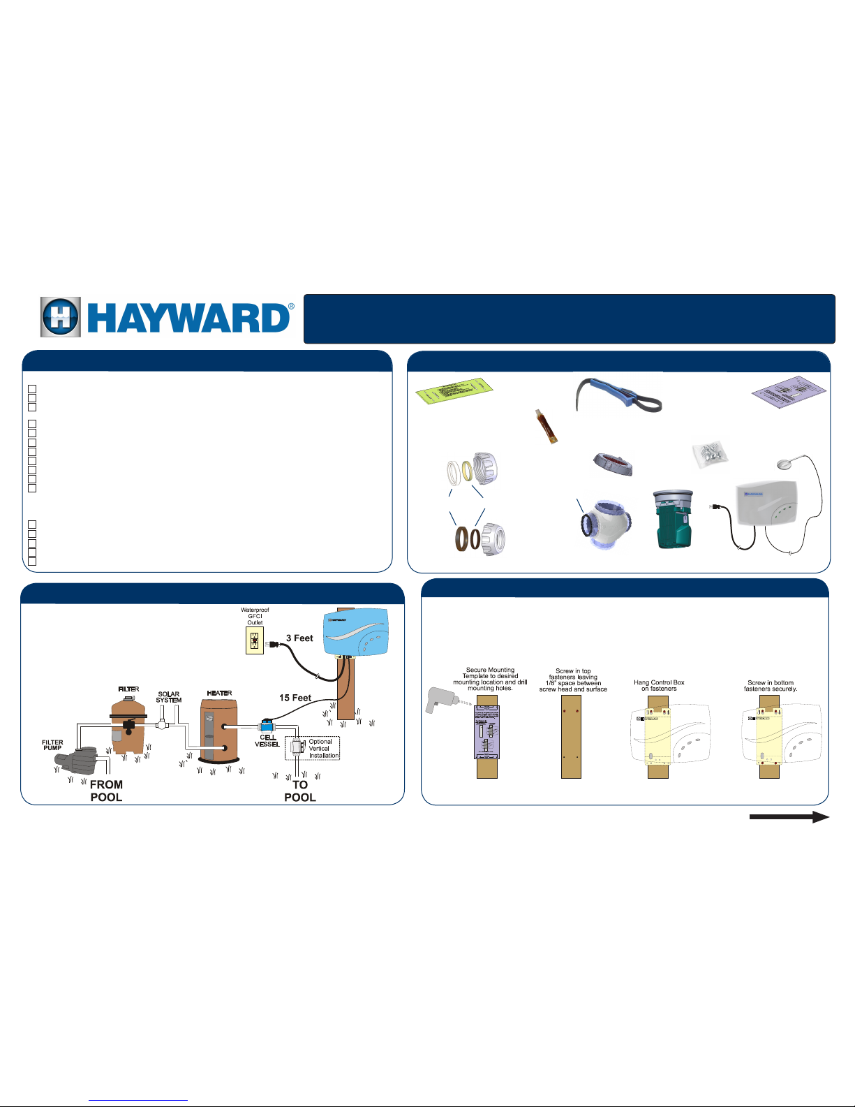
The Control Box will be mounted within 3 feet of a 120V GFCI outlet
The Control Box will be mounted within 15 feet of the installed Cell Vessel
The Control Box will be installed at least 10 feet away from the pool.
Pool plumbing is 1½” or 2” PVC (If black polyethylene pipe is used, see manual)
You have a saw suitable for cutting PVC
You have tools for mounting the Control Box (drill, drill bits, screwdriver)
You have a permanent marker to mark the PVC pipe
You have balanced your pool chemistry and have 3200ppm salt in your pool (see Chemistry
Quick Start Guide)
Read this entire Quick Start Guide
Remove power to lter pump
Drain water from pool piping
Verify that all parts are included in the box
You are wearing safety glasses and have read the safety precautions in the owner’s manual
Before you begin
Overview
WWW.HAYWARD.COM 855-429-9274
Pre-Installation Checklist
Installation Preparation
Turn Over
Spread out parts on ground
2” Nut Assembly (2)
1.5” Nut Assembly (2)
Control Box
Screws
Strap Wrench
Compression
Ring
Collar
STEP 1: Mount Control Box
Mount the Control Box to a wall or post within 3 feet of a GFCI outlet, making sure that the cord will
reach. The Control Box will also have to be mounted within 15 feet of the Cell Vessel as shown in the
Overview.
Use the included Mounting Template to help locate the mounting holes and fasten the Control Box to the
intended surface.
Control Box
Mounting
Template
Cell Cap & Cord
Cell Vessel
Cutting Template
Grease
Retaining Nut
Cell Vessel
Gasket (2)
SAS-CELL
(sold separately)
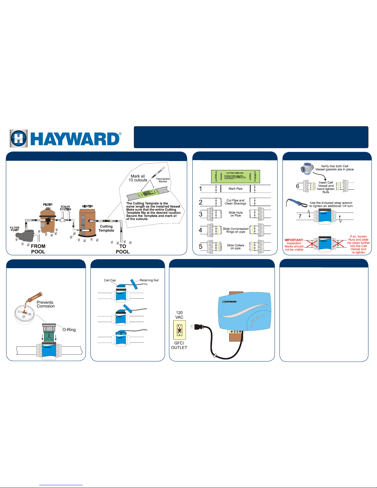
With the pump off and water chemistry adjusted (see Water
Chemistry Quick Start Guide), plug linecord into a 120 VAC
ground fault circuit interrupter (GFCI) safety outlet or an outlet
protected by a ground fault circuit breaker (GFCB). If local
codes require bonding, see manual.
092509 RevA
STEP 8: Calibrate Flow Switch
STEP 7: Plug in Linecord
1. After being powered on for the rst time, the Salt
& Swim will display a blinking INADEQUATE
WATER FLOW LED and a solid STANDING BY
LED. Keep the Salt & Swim powered for the
remainder of this procedure.
2. Turn the lter pump ON. Make sure that full ow
is achieved (no air in the system) and run the
pump for at least 15 seconds.
3. Turn the lter pump OFF for 15 seconds.
4. The Salt & Swim should now display a solid
INADEQUATE WATER FLOW and a solid
STANDING BY LED. The Flow Switch Calibration procedure is complete. You can now turn on
your lter pump and begin normal operation.
STEP 3: Install Nut Assembly
Follow the procedure below to install the Nut
Assembly.
Remove the foam protector from the SASCELL. Fully cover Cell pins with supplied
grease. Verify that the O-ring is attached to
the Cell before inserting the Cell into the Cell
Vessel as shown.
STEP 5: Insert Cell
STEP 4: Install Cell Vessel
STEP 6: Attach Cap
Plug in Cell Cap and secure with
Retaining Nut.
Run the pump for 5 minutes or until all air
is out of the system. Check for leaks and
then turn the pump off.
STEP 2: Determine where Cell Vessel will be installed
The Cell Vessel must be the very last component installed in the
pool’s return piping before the water returns back to the pool. It can be
installed vertically or horizontally and requires approximately 10 inches
of straight pipe at the installation location.
Use the included Cutting Template to aid in marking and cutting
the pipe. The entire Cutting Template must t on the pipe
otherwise the Cell Vessel will not t. Secure the Template and
use a permanent marker to mark all 10 cutouts.
Salt & SwimTM 3C Installation Quick Start
IMPORTANT!
 Loading...