

HAYWARD 210T1580 User Manual

Your Hayward Pro Series high-rate sand filter is a high
performance, totally corrosion-proof filter that blends superior
flow characteristics and features with ease of operation. It
represents the very latest in high-rate sand filter technology . It
is virtually foolproof in design and operation. When installed,
operated and maintained according to instructions, your filter
will produce clear, sparkling water with minimal attention and
care.
HOW IT WORKS
Your filter uses special filter sand to remove dirt particles from
pool water. The filter sand is loaded into the filter tank and
functions as the permanent dirt removing media. The pool
water, which contains suspended dirt particles, is pumped
through your piping system and is automatically directed by
the patented filter control valve to the top of the filter tank. As
the pool water is pumped through the filter sand, dirt particles
are trapped by the sand bed, and filtered out. The cleaned
pool water is returned from the bottom of the filter tank,
through the control valve and back to the pool through the
piping system. This entire sequence is continuous and
automatic and provides for total recirculation of pool water
through your filter and piping system.
After a period of time, the accumulated dirt in the filter causes
a resistance to flow, and the flow diminishes and the pressure
gauge rises. This means it is time to clean (backwash) your
filter. With the control valve in the backwash position, the
water flow is automatically reversed through the filter so that is
directed to the bottom of the tank, up through the sand,
flushing the previously trapped dirt and debris out the waste
line. Once the filter is backwashed (cleaned) of dirt, the
control valve is manually positioned to Rinse, and then
positioned to Filter to resume normal operation.
INSTALLATION
Only simple tools (screwdriver and wrenches), plus pipe
sealant for plastic adapters, are required to install and/or
service filter.
The filter system must be placed on level, very firm,
ground. Position the filter so that the piping connections,
control valve and winter drain are convenient and
accessible for operation, service and winterizing.
Assemble the Pump to the platform base. The adapters
must now be installed to connect the pump/filter system.
Apply Teflon pipe sealant tape or Permatex No. 2
sealant to straight adapter. Screw adapter into pump
discharge port. (Do not overtighten.)
Apply Teflon pipe sealant tape or Permatex No. 2
sealant to elbow adapter. Screw adapter securely into
opening in control valve marked PUMP. (Do not
overtighten.)
Loading sand media. Filter sand media is loaded through
the top opening of the filter.
Loosen flange clamp and remove Filter Control Valve
(if previously installed).
Cap internal pipe with sand shield to prevent sand from
entering it. Be sure pipe is securely in place in bottom
underdrain hub.
We recommend filling tank approximately 1/2 way with
water to provide a cushioning effect when the filter
sand is poured in. This helps protect the underdrain
laterals from excessive shock. (Be sure the winter drain
cap is securely in place on drain pipe.)
1.
2.
a.
b.
IS210T1580-01
3.
a.
b.
39-1/2”
(100 cm)
29-1/2”
(75 cm)
16” (41 cm)
c.
SPECIFICATIONS
MODEL
NUMBER
EFFECTIVE
FILTRATION
AREA
DESIGN
FLOW
RATE*
PRESSURE
LOSS AT
DESIGN
FLOW RATE
MAXIMUM
WORKING
PRESSURE
REQUIRED CLEARANCE
SIDE ABOVE
MEDIA REQUIRED
TYPE AMOUNT
*Based on 20 GPM/ft.2/ 813.98 LPM/m2(maximum allowable NSF rating).
S210T1580
FT
2
0.21
M
2
2.2
GPM LPM
44
167
PSI BAR
2
0.14
PSI
BAR INCH MM
INCH
MM
200
91
KGSLBS
50
3.45
457
18 457
18
FILTER SAND
0.45-0.55 mm
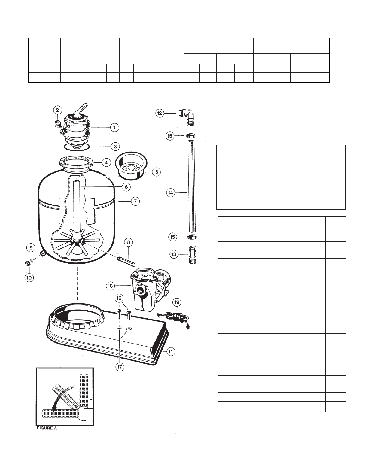
PARTS
S210T1580
Filter Systems
NOTE: NSPI-4 Article V, standard for above-ground and
on-ground pools, advises that components such as the
filtration system, pumps and heater be positioned so as
to prevent their being used as a means of access to the
pool by young children.
NOTE: The System Base has provisions for mounting optional
timer and optional automatic chlorinator. See dealer for details.
REF.
NO.
1
2
3
4
5
6
7
8
9
10
11
12
13
14
15
16
17
18
19a
19b
NO.
REQ’D.
1
1
1
1
1
1
1
10
1
1
1
1
1
1
2
2
2
1
1
1
PART NO.
SP0714T
ECX27081
GMX600F
GMX600N
SX202S
SX180DA
SX210AA2
SX200Q
SX180G
SX180H
SX180K
SPX1105Z4
SPX1091Z2
SX160Z3
ECX18028
ECX1108
ECX1109
-----------SPX1250WA
SPXI550WA
DESCRIPTION
Multiport Valve
Pressure Gauge
Valve/Tank O-Ring
Flange Clamp (Valve-Tank)
Sand Shield
Lateral Assembly with
Center Pipe
Filter Tank with
Complete Lateral Assembly
Lateral
Gasket
Drain Cap
System Mounting Base
1-1/2” Elbow Adapter
1-1/2” Straight Hose Adapter
1-1/2” Hose
Hose Clamp
5/16” x 3/4” Mounting Screw
5/16” Washer
Power-Flo LX Pump
6 ft. Cord Set
3 ft. Twist Lock Cord Set
a
b
 Loading...