

Page 1

H15/40
HERITAGE TRACTOR
CODE145S
INSTRUCTION BOOK
FROM SERIAL NO:145S001251 MANUAL PART NO:145010 (REV.0.)
F–000794J
Page 2
5 (0011x3)
1
2
4 (711758)
6
3
3
2
1
2
1
3
4 (711644)
1 (711719)
2 (711663)
1
2
5 (711747)
4
3
5
3
5
1
6
7
6 (711636)
7 (711680)
3
10
2
9
8
11
7
5
6
6
4
1
F–000794J
2
2
Page 3
10
12
11
7
7
2
5
6
3
8
1
4
9
1
2
6
5
2
1
8
3
7
7
2
1
8
3
11
1
10
6
5
12
F–000794J
2
1
2
3
4
5
3
Page 4
13
12
4
11
5
2
1
9
3
10
8
14
F–000794J
15
1
1
2
3
2
16
4
Page 5
17
2
18
3
1
4
1
19
1
2
F–000794J
20
3
2
1
3
4
4
5
1
21
Page 6
22
23
3
2
1
24
1
2
1
2
25
1
3 (711909)
2
4 (711632)
2
1
3
26
711653
711653
27
2
F–000794J
3
6
Page 7
28
29
5
30
3
6
1
6
5
7 (711741)
31
F–000794J
4
1
32
33
2
1
7
Page 8
34
1
2
35
1
1
2
1
3
37
4
3
2
36
F–000794J
4
3
2
5
8
Page 9
38
J
8
4
2
1
A
2
1
4
6
5
E
B
3
11
C
F
3
9
F–000794J
D
10
H
9
Page 10
39
12 3 5467
9
16 18
10
17
1211 13
14 15
8
40
12 3456 78 9
10 11 12 13 14 15
0011x3
711758
711719
711663
711644
711680
41
327350
711747
711636
F–000794J
711909
711653
10
711632
711741
Page 11
LIMITED WARRANTY
Hayter Limited warrants to the original user / purchaser that this unit shall be free from defects in material and
workmanship under normal use and service for a period of three years from the date of purchase. The manufacturers of the engine and battery pack system (where applicable) furnish their own warranty and services are provided through their authorised network (Refer to “Engine/Battery Pack Warranty Statement”). To qualify for the
full benefit of the warranty , the warranty registration card must be returned within 60 days of purchase. Subject to
the conditions and exclusions noted in this limited warranty, we shall at our option, repair or replace any warranted part during the applicable period. If you are in doubt or experience any difficulty, please consult a Hayter
Authorised Service Dealer for clarification..
To qualify for the extended warranty (second and third year) of the three year limited warranty , the machine must
have annual services carried out by an Authorised Hayter Service Dealer. These chargeable services should be
carried out within 12 and 24 months of the date of purchase.
Excluded from the extended warranty period are those items which are subject to normal wear and tear e.g. tyres,
wheels, cutterbars, cables, batteries and other consumable wearing parts.
All consumer machines which are fitted with a genuine Hayter friction disc as original equipment, before use, are
covered by a Lifetime Warranty against the engine crankshaft bending. Note: friction washers, blade brake
units and other such devices are not applicable. Only machines fitted with a genuine Hayter friction disc, which
are used in accordance with the recommended operating and maintenance procedures, are covered.
This warranty does not apply to any unit that has been tampered with, altered, misused, abused or used for hire,
and will become invalid if non genuine Hayter parts are fitted. This warranty does not cover minor mechanical
adjustments unless they are due to defective materials or workmanship. Consult the Owner’s Handbook or a
Hayter Authorised Service Dealer for assistance when making these adjustments.
A warranty period of 90 days applies to machines used for commercial purposes.
To make a warranty claim, return the unit to a Hayter authorised dealer along with proof of purchase stating the
machine serial number and date of purchase. The service receipt(s) or this Owner’s Handbook with the 1st/2nd
year service boxes fully completed, must be produced as proof of entitlement to the extended warranty period.
Subject to the conditions and exclusions in this limited warranty , the authorised dealer will, at our option, repair or
replace any warranted part within the duration of the warranty period.
This limited warranty gives you specific legal rights and is in addition to any statutory rights to which you may be
entitled and your statutory rights are not affected by this warranty. If you need additional information concerning
this written warranty, or assistance in obtaining services, please write to:
HAYTER LIMITED, Service Department, Spellbrook, Bishop’s Stortford, Hertfordshire. CM23 4BU.
GB
F–000794J
UK ONLY: Details of your local Hayter authorised dealer are contained in Y ellow Pages or contact: Freephone 0800 616298.
1st
Year
Service
Record
Date . . . . . . . . . . . . . . . . . . . . . . . . . . . . . . . . . . . . . . . . .
Signed . . . . . . . . . . . . . . . . . . . . . . . . . . . . . . . . . . . . . . . .
2nd
Year
Service
Record
Date . . . . . . . . . . . . . . . . . . . . . . . . . . . . . . . . . . . . . . . . .
Signed . . . . . . . . . . . . . . . . . . . . . . . . . . . . . . . . . . . . . . . .
11
Page 12

CONTENTS
LIMITED WARRANTY 11
INTERNATIONAL PICTORIALS 12
OWNER’S INFORMATION 13
SAFE OPERATION PRACTICES 13
ASSEMBLY 14
OPERATION 15
MAINTENANCE 17
TROUBLE SHOOTING CHART 20
GB
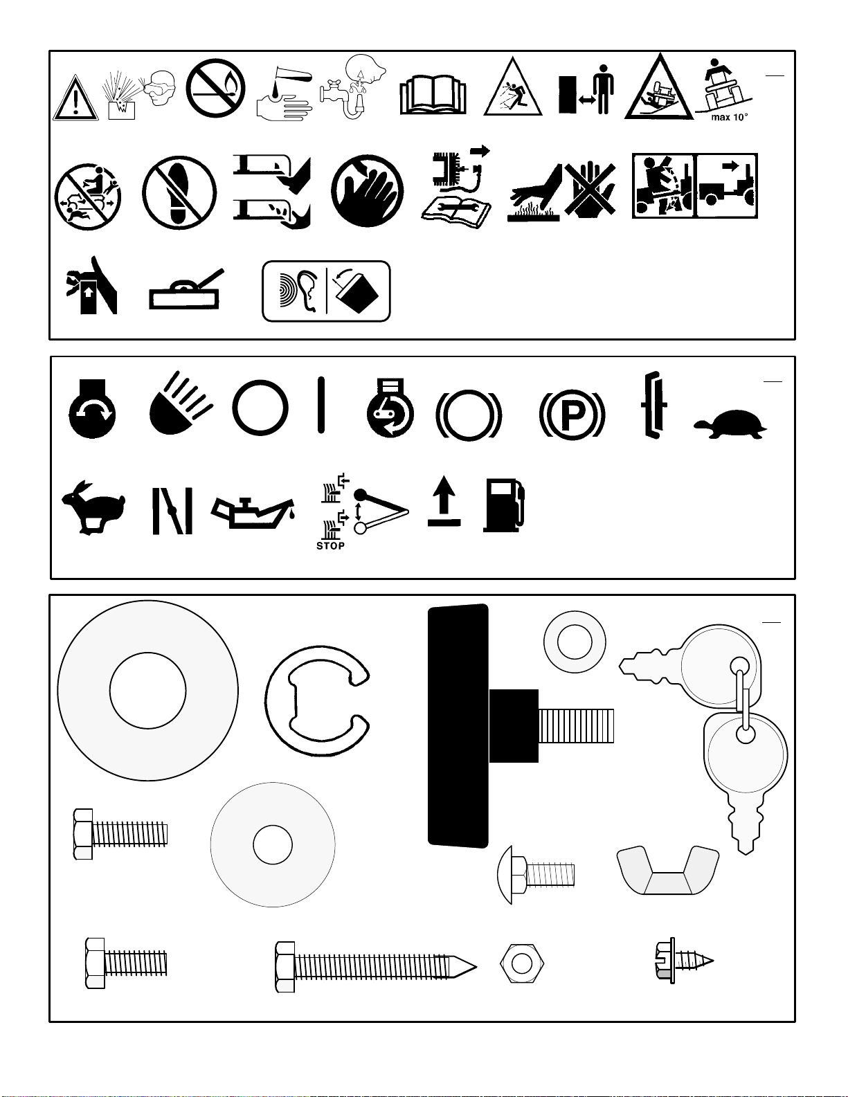
INTERNATIONAL PICTORIALS
IMPORTANT: The following pictorials are located on your unit or on literature supplied
with the product. Before you operate the
unit, learn and understand the purpose for
each pictorial.
NOTE: Illustrations and pictorials begin
on page 2.
Safety Warning Pictorials
1 WARNING
2 Shield Eyes. Explosive Gases Can Cause
Blindness Or Injury.
3 No Sparks, Flames or Smoking.
4 Sulphuric Acid Can Cause Blindness Or
Severe Burns
5 Flush Eyes Immediately With Water. Get
Medical Help Fast.
6 IMPORTANT: Read Owner’s Manual
Before Operating This Machine.
7 WARNING: Thrown Objects. Keep
(Figure 39)
Bystanders Away. Read User Instructions
Before Operating This Machine.
8 WARNING: Do Not Use This Machine On
Slopes Greater Than 10 Degrees.
9 DANGER: Keep People, Especially
Children, Away From Unit.
10 DANGER: No Step.
11 DANGER: Keep Feet And Hands Away
From Rotating Blade.
12 DANGER: Keep Hands Away From
Rotating Blade.
13 DANGER: Disconnect Spark Plug Wire
Before Servicing Unit.
14 WARNING: Hot Surface.
15 WARNING: Use Caution When Connecting
Or Disconnecting Accessories.
16 WARNING: Crushed Fingers.
17 IMPORTANT: Follow Instructions In
Owner’s Manual To Level The Deck.
18 WARNING: When you hear the audible
alarm it is time to empty the grass bagger.
Control And Operating Pictorials
(Figure 40)
1 Engine Start
2 Lights
3 Engine Run
4 Engine Stop
5 Engine Run
6 Brake
7 Parking Brake
8 Clutch
9 Slow
10 Fast
11 Choke
12 Oil
13 Blade Rotation Control
14 Raise
15 Fuel
MADE IN USA BY MURRAY INC.
JACKSON, TENNESSEE
FOR
CODE145S
15/40 TRACTOR
HYDRO/REAR COLLECT
249
F–000794J
RPM 2600
2000
145S001251
Declared vibration emission values in accordance with Directive 89/392/EEC.
Vibration Emission according to BS EN 1032: Seat < 0,50 m/s2,
Right Running Board < 0,50 m/s2, Left Running Board 0,54 m/s2
Vibration Emission according to BS EN 1033: Steering Wheel 3,85 m/s
Values determined with operator in operating position when the machine was
operated stationary on a grass covered surface at 2600 min–1.
Declared airborne noise emissions in accordance with Directive 84/538/EEC.
Sound Power Level 100 dB(A)
Sound Pressure Levels
at operator ears 85,3 dB(A) left; 85,2 dB(A) right.
Values determined at ear according to the specifications of 81/1051/EEC.
2
12
Page 13

OWNER’S INFORMATION
Know your product: If you understand the unit
and how the unit operates, you will get the best
performance. As you read this manual, compare
the illustrations to the unit. Learn the location
and the function of the controls. To help prevent
an accident, follow the operating instructions
and the safety rules. Keep this manual for future
reference.
WARNING: Look for this symbol to indicate
important safety precautions. This symbol
indicates: “Attention! Become Alert! Your
Safety Is At Risk.”
Responsibility Of The Owner
WARNING: This cutting machine is
capable of amputating hands and
feet and throwing objects. Failure
to observe the following safety instructions
could result in serious injury or death to
the operator or bystanders.
The responsibility of the owner is to
follow the instructions below.
SAFE OPERATION PRACTICES
For Ride–On (Riding)
Rotary Mower Machines
Training
1. Read the instructions carefully. Be familiar
with the controls and the proper use of the
equipment.
2. Never allow children or people unfamiliar
with these instructions to use the mower.
Local regulations may restrict the age of
the operator.
3. Never mow while people, especially
children, or pets are nearby.
4. Keep in mind that the operator or user is
responsible for accidents or hazards occurring to other people or their property.
5. Do not carry passengers.
6. All drivers should seek and obtain professional and practical instruction. Such
instruction should emphasize:
a. the need for care and concentration
when working with ride–on machines;
b. control of a ride–on machine sliding
on a slope will not be regained by the
application of the brake. The main
reasons for loss of control are:
insufficient wheel grip;
being driven too fast;
inadequate braking
the type of machine is unsuitable
for its task;
lack of awareness of the effect of
ground conditions, especially
slopes;
incorrect hitching and load dis-
tribution.
Preparation
1. While mowing, always wear substantial
footwear and long trousers. Do not operate
the equipment when barefoot or wearing
open sandals.
F–000794J
2. Thoroughly inspect the area where the
equipment is to be used and remove all objects which may be thrown by the machine.
3. WARNING – Petrol is highly flammable.
a. Store fuel in containers specifically de-
signed for this purpose.
b. Refuel outdoors only and do not
smoke while refuelling.
c. Add fuel before starting the engine.
Never remove the cap of the fuel tank
or add petrol while the engine is running or when the engine is hot.
d. If petrol is spilled, do not attempt to
start the engine but move the machine
away from the area of spillage and
avoid creating any source of ignition
until petrol vapours have dissipated.
e. Replace all fuel tanks and container
caps securely.
4. Replace faulty silencers.
5. Before using, always visually inspect to see
that the blades, blade bolts and cutter assembly are not worn or damaged. Replace
worn or damaged blades and bolts in sets
to preserve balance.
6. On multi–blade machines, take care as rotating one blade can cause other blades to
rotate.
Operation
1. Do not operate the engine in a confined
space where dangerous carbon monoxide
fumes can collect.
2. Mow only in daylight or in good artificial
light.
3. Before attempting to start the engine, disengage all blade attachment clutches and
shift into neutral.
4. Do not use on slopes of more than 10 degrees.
5. Remember there is no such thing as a
“safe” slope. Travel on grass slopes requires particular care. To guard against
overturning:
a. do not stop or start suddenly when
going up or downhill;
b. engage clutch slowly, always keep
machine in gear, especially when travelling downhill;
c. machine speeds should be kept low
on slopes and during tight turns;
d. stay alert for humps and hollows and
other hidden hazards;
e. never mow across the face of the
slope, unless the mower is designed
for this purpose.
6. Use care when pulling loads or using heavy
equipment.
a. Use only approved drawbar hitch
points.
b. Limit loads to those you can safely
control.
c. Do not turn sharply. Use care when
reversing.
d. Use counterweight(s) or wheel
weights when suggested in the Instruction Book.
7. Watch out for traffic when crossing or near
roadways.
8. Stop the blades rotating before crossing
surfaces other than grass.
9. When using any attachments, never direct
discharge of material toward bystanders
13
GB
nor allow anyone near the machine while in
operation.
10. Never operate the mower with defective
guards or shields, or without safety protective devices in place.
11. Do not change the engine governor settings or overspeed the engine. Operating
an engine at excessive speed may increase the hazard of personal injury.
12. Before leaving the operator’s position
a. disengage the power take–off and
lower the attachments;
b. change into neutral and set the park-
ing brake;
c. stop the engine and remove the key.
13. Disengage drive to attachments, stop the
engine, and disconnect the spark plug
wire(s) or remove the ignition key
a. before cleaning blockages or unclog-
ging chute;
b. before checking, cleaning or working
on the mower;
c. after striking a foreign object. Inspect
the mower for damage and make repairs before restarting and operating
the equipment;
d. if the machine starts to vibrate abnor-
mally (check immediately).
14. Disengage drive to attachments when
transporting or not in use.
15. Stop the engine and disengage drive to attachment
a. before refuelling;
b. before removing the grass catcher;
c. before making height adjustment un-
less adjustment can be made from the
operator’s position.
16. Reduce the throttle setting during engine
run–out and, if the engine is provided with a
shut–off valve, turn the fuel off at the conclusion of mowing.
17. Before and when backing, look behind and
down for small children.
18. Use extra care when approaching blind
corners, shrubs, trees or other objects that
may obscure vision.
Maintenance and Storage
1. On multi–blade machines, take care as rotating one blade can cause other blades to
rotate.
2. When machine is to be parked, stored or
left unattended, lower the cutting means
unless a positive mechanical lock is used.
3. Keep all nuts, bolts, and screws tight to be
sure the equipment is in safe working
condition.
4. Never store the equipment with petrol in the
tank inside a building where fumes may
reach an open flame or spark.
5. Allow the engine to cool before storing in
any enclosure.
6. To reduce the fire hazard, keep the engine,
silencer, battery compartment and petrol
storage area free of grass, leaves, or excessive grease.
7. Check the grass catcher frequently for
wear or deterioration.
8. Replace worn or damaged parts for safety.
9. If the fuel tank has to be drained, this
should be done outdoors.
Page 14

ASSEMBLY
n
f
All fasteners are in the parts bag. Do not discard
any parts or material until the unit is assembled.
WARNING: Before doing any assembly or maintenance to the
mower, remove the wire from the
spark plug.
NOTE: In this instruction book, left and right
describe the location of a part with the operator on the seat.
NOTE: Illustrations and pictorials begin on
page 2.
NOTE: To assemble the following loose
parts, use the fasteners shown at full size in
Figure 41.
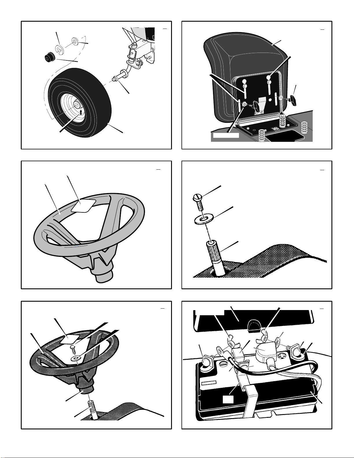
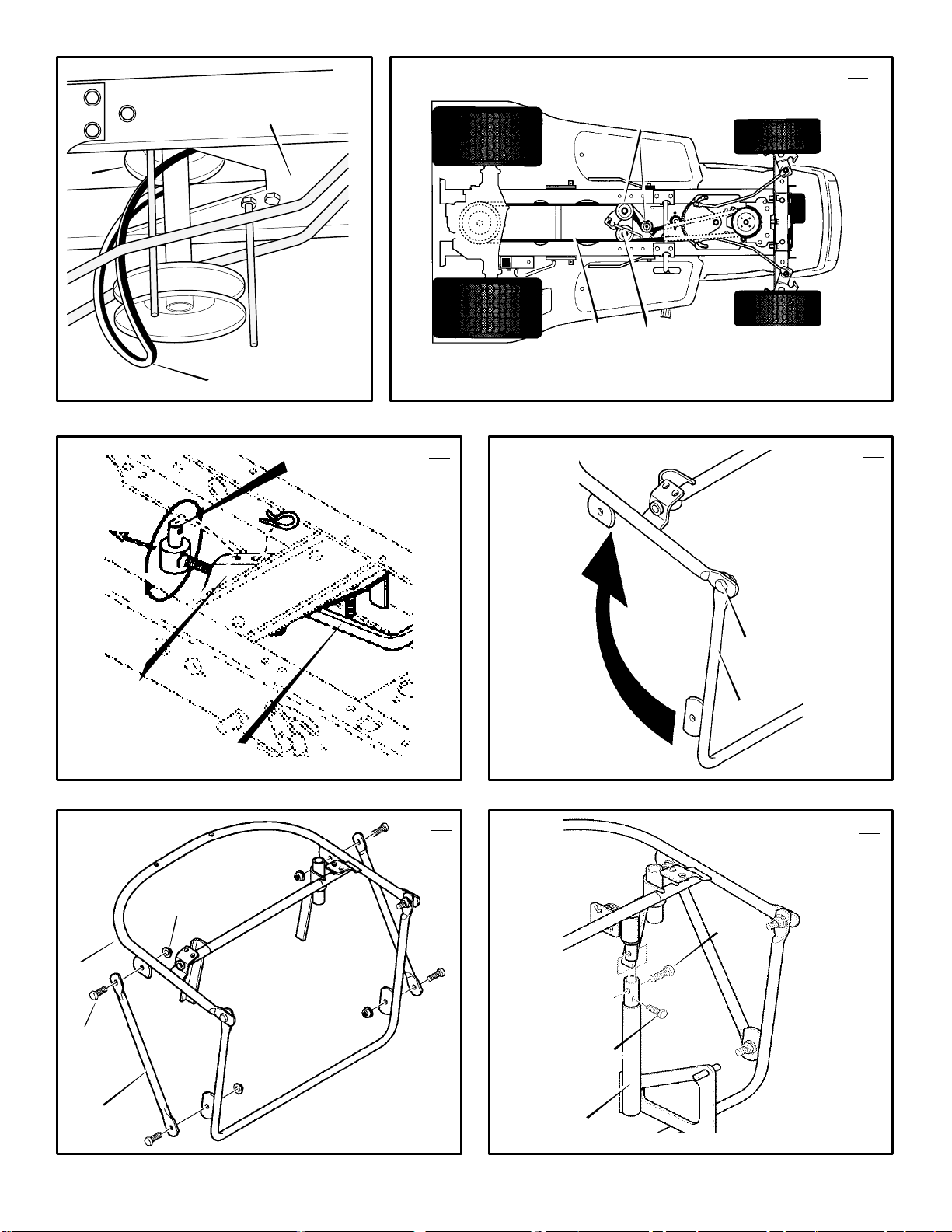
How To Install The Front Wheels
(Figure 1)
Use a knife and cut the four sides of the container.
Install the front wheels (1) in the container.
NOTE: Use a piece of wood about 4 feet (1.25
meters) long to raise the front of the tractor.
If a piece of wood cannot be found, get
another person to help lift the tractor. Be
careful, do not let the tractor fall.
1. Raise the front of the tractor. Set a support
(block of wood) under the tractor.
2. Make sure the valve stem (2) is to the outside of the tractor. Slide the front wheel (1)
on the spindle (3).
3. Fasten each front wheel (1) with washer (4)
and e–ring (5).
4. After the front wheels (1) are installed, lift
the tractor from the support. Roll the tractor
off of the container.
5. If your tractor has hub caps (6), install the
hub caps (6). Make sure the washers (4)
hold the hub caps (6) in place.
How To Install The Seat
1. Carefully remove the plastic bag from the
seat (1).
NOTE: For shipping purposes, the fas-
teners may be attached to the seat. Before proceeding, remove the fasteners.
2. Align the holes in the seat hinge (2) to the
bolts in the seat (1). Fasten the seat (1) to
the seat hinge (2) with the fasteners (4) and
(5).
3. Check the operating position of the seat (1).
If the seat (1) needs to be adjusted, loosen
the two wing bolts (5). Slide the seat (1) for-
ward or backward along the seat adjusting
holes (3). Tighten the wing bolts (5).
How To Assemble The Steering Wheel
1.
(Figure 3)
cover (1) is taped to the center of the steer-
ing wheel (2). Remove the hub cover (1)
and set aside.
2.
(Figure 4)
(2) from the steering post (3) and set aside.
3. Make sure the front wheels point forward.
4.
(Figure 5)
make sure the split spoke (5) of the steering
wheel in pointing toward you. Slide the steer-
ing wheel (1) onto the steering post (2).
5. Use screw (6) and washer (7), set aside
earlier, to secure the steering wheel (1).
Tighten the screw (6). DO NOT over tighten.
F–000794J
For shipping purposes, the hub
Remove screw (1) and washers
From the operator’s position,
(Figure 2)
6. Remove the adhesive backing from the hub
cover (3) that was set aside earlier. Attach
the hub cover (3) to the center of the steering wheel (1).
7. Some models have an
parts bag. Attach the decal to the center of
the steering wheel (1).
Maintenance Free Battery
IMPORTANT: Before you attach the battery
cables to the battery, check the battery date.
The battery date tells if the battery must be
charged.
1. Check the top of the battery (1) for the location of the battery date.
2. If the battery (1) is put into service
the battery date, the battery cables can be
attached without charging the battery (1).
See “How To Install The Battery Cables”.
3. If the battery (1) is put into service
battery date, the battery (1) must be
charged. See “How To Charge The Maintenance Free Battery”.
optional
(Figure 6)
decal in the
before
after
the
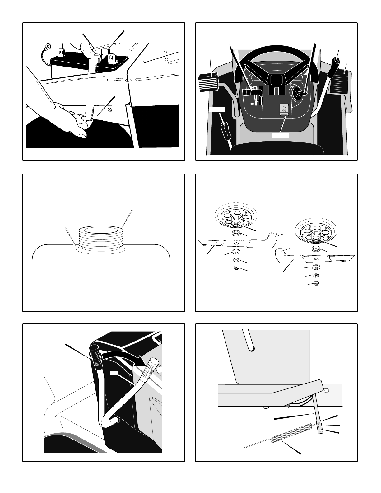
How To Charge The Battery
WARNING: When you charge the
battery, do not smoke. Keep the bat-
fumes from the battery acid can cause an
explosion.
1.
2. Remove the fasteners (9) from the battery
3.
4. Remove battery bracket (11).
5. Remove the battery (1).
6. Remove the protective caps from the battery
7. Use a 12 volt battery charger to charge the
8. Install the battery (1).
9. Install battery brackets (10, 11).
NOTE: Make sure battery brackets (10, 11)
are installed into the slots in the frame (12)
before tightening the fasteners.
tery away from any sparks. The
(Figure 6)
brackets (10, 11).
(Figure 7)
(10) and remove battery bracket (10) from
frame (12) as shown.
terminals.
battery (1). Charge at a rate of 6 amperes
for one hour. If you do not have a battery
charger, have an authorized service centre
charge the battery.
Remove the battery cover (3).
WARNING: To prevent sparks, do
not touch the battery brackets to
the terminals.
Apply pressure to battery bracket
How To Install The Battery Cables
(Figure 6)
WARNING: To prevent sparks, faste
the red cable to the positive (+) ter-
cable.
1. Remove the protective caps from the battery
2. Fasten the red cable (5) to the positive (+)
minal before you connect the black
terminals.
NOTE: For shipping purposes, the fasteners may be attached to the battery terminals. Remove the fasteners before
proceeding.
terminal (4) with the fasteners (6) and (7).
Slide the terminal cover (2) onto the positive (+) terminal (4).
14
GB
3. Fasten the black cable 8 to the negative (–)
terminal with the fasteners (6) and (7).
4. Install the battery cover (3).
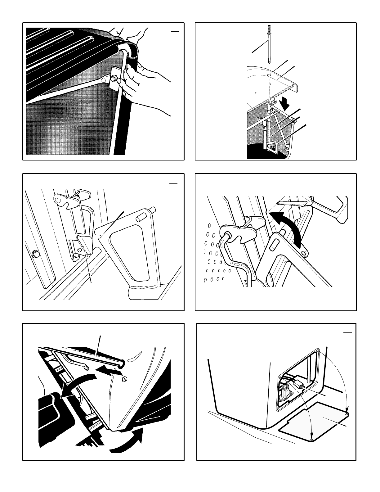
How To Assemble The Grass Bagger
1. Put the grass bagger on a flat surface.
2.
(Figure 25)
teners (2).
3.
(Figure 26)
assembly (1) with screws (3) and nuts (4).
Make sure all fasteners are tight.
4.
(Figure 27)
brackets (3) with the fasteners as shown.
5.
(Figure 28)
6.
(Figure 29)
bagger assembly (1), slide the handle (5) in
the tube (6).
7. Fasten the handle (5) with screw (7).
How To Mount
The Grass Bagger On The Tractor
1.
(Figure 30)
brackets (3) onto the pins (4) on the back
plate of the tractor.
2.
(Figure 31)
grass bagger in operating position. Snap into
place.
How To Prepare The Engine
NOTE: The engine was shipped from the factory filled with oil. Check the level of the oil.
Add oil as needed.
See the engine manufacturer’s instructions for the
type of petrol and oil to use. Before you use the
unit, read the information on safety, operation,
maintenance, and storage.
safety petrol container. Do not smoke when
adding petrol to the engine. When inside an
enclosure, do not fill with petrol. Before you
add petrol, stop the engine. Let the engine
cool for several minutes.
Check The Tyres
Check the air pressure in the tyres. Tyres with too
much air pressure will cause the unit to ride rough.
Also, the wrong air pressure will keep the mower
housing from cutting level. The correct air pressure is: Front Tyres 1,38 BAR (20 PSI), Rear
Tyres 0,97 BAR (14 PSI). The tyres were over inflated for shipment.
Check The Level Of The Mower Housing
Make sure the level of cut is still correct. After you
mow a short distance, look at the area that was cut.
If the mower housing does not cut level, see the instructions on “How To Level The Mower Housing”
in the Maintenance section of this instruction book.
Important! Before You Start Mowing
Check the engine oil.
Fill the fuel tank with petrol.
Check the level of the mower housing.
Check the air pressure of the tyres.
Attach the battery cables.
Open the frame (1). Tighten fas-
Attach braces (2) to the frame
Attach the bag support
Secure the bag to the frame.
On the left side of the grass
Mount the slots on the support
Hold rear handle and rotate the
WARNING: Follow the engine manufacturer’s instructions for the type o
petrol and oil to use. Always use a
Page 15

OPERATION
NOTE: Illustrations and pictorials begin on
page 2.
Location Of Controls
Blade Rotation Control (1): Use the blade
rotation control to start and stop the rotation of the
blade.
Brake Pedal (2): Use the brake pedal to quickly
stop.
Headlight Switch (3): The headlight switch is the
first part of the ignition switch. T o use the lights with
the engine running, turn the key to the position for
the lights.
Ignition Switch (3): Use the ignition switch to
start and stop the engine.
Speed Control Pedal (4): Use the speed control
pedal to change the speed and the direction of the
unit.
Lift Lever (5): Use the lift lever to change the
height of cut.
Parking Brake Lever (6): Use the parking brake
lever to engage the brake when you leave the unit.
Throttle Control Lever (7): Use the throttle
control lever to increase or decrease the speed of
the engine. For models without a choke control
button, the choke is regulated with the throttle
control lever.
Choke Control Button (9): If equipped, used to
start cold engine.
(Figure 35)
Use the automatic drive disconnect, located at the
left back corner of the seat, to disengage the
transmission.
Grass Bagger Full Indicator (10): When you
hear the audible alarm the grass bagger is full.
Move the blade rotation control (1) to the
DISENGAGE position to turn audible alarm off and
see the “How To Empty The Grass Bagger”
instructions in this section.
IMPORTANT: For the diagnostic dash to operate properly the engine MUST use a resistor spark plug. When replacing the spark
plug see the engine owner’s manual for the
correct spark plug.
Automatic Drive Disconnect (1):
Diagnostic Dash
PTO/Clutch engaged. To start the
engine, disengage the
PTO/Clutch.
Service Light. Refer to Hour
Meter, Instruction Book and
Engine Manual for scheduled
service. Service Light stays ON
until reset procedure is followed.
25
F–000794J
Hour Meter. Records the engine
runtime in hours.
Low Fuel. Fill fuel tank.
Low Oil Pressure. STOP
ENGINE!. Check and add oil.
Low Battery Voltage. Check
battery, battery cables and engine
charging system.
(Figure 8)
How To Reset The Service Light
To alert the operator that scheduled service is due,
the service light will automatically come ON. After
the scheduled service is performed, the service
light can be easily reset as follows.
1. Raise the hood. Locate the reset button. The
reset button is above the fuel tank on the
right side of the console. The following decal
is next to the reset button.
2. Turn the ignition key to the ON/RUN position.
Do not turn the ignition key to the START
position. Do not start the engine.
3. All indicator lights will come on for two seconds.
4. After two seconds, the service light will begin
flashing for ten seconds.
5. Depress and release the reset switch while
the service light is flashing. The service light
will go off.
6. The reset switch will only turn off the service
light. The hour meter cannot be reset.
Diagnostic Fuse
Replace fuse only with a 3 AMP 32 volt fuse. For
location of fuse see “How To Replace The Fuse”
in the Maintenance section.
Attachments
This unit can use many different attachments. This
unit can pull attachments like a lawn sweeper, a
lawn aerator, or a hopper spreader. This unit can
not use attachments that engage the ground like
a plough, a disk harrow, or a cultivator.
For trailer and pull–behind attachments, the
maximum weight is 113 kg (250 lbs.).
How To Use The Throttle Control
(Figure 8)
Use the throttle control (7) to increase or
decrease the speed of the engine.
1. The FAST position is marked with a detent.
For normal operation and when using a
grass bagger, move the throttle control to the
FAST position. For maximum charging of the
battery and for a cooler running engine, operate the engine in the FAST position.
2. The engine governor is set at the factory for
maximum performance. Do not adjust the
governor to increase the speed of the engine.
How To Use The Blade Rotation Control
(Figure 8)
Use the blade rotation control (1) to engage the
blade(s).
1. Before you start the engine, make sure the
blade rotation control (1) is in the DISENGAGE position.
2. Move the blade rotation control (1) to the
ENGAGE position to rotate the blade(s).
NOTE: If the engine stops when you engage the blade(s), the seat switch is not
activated or the bag is not closed properly. Make sure you sit in the middle of the
seat.
3. Move the blade rotation control (1) to the
DISENGAGE position to stop the blade(s).
15
GB
Before you leave the operator’s position,
make sure the blade(s) has stopped rotating.
4. Before you ride the unit across a sidewalk or
a road, move the blade rotation control (1)
to the DISENGAGE position.
WARNING: Always keep your
hands and feet away from the
blade, deflector opening, and the
mower housing when the engine runs.
How To Use The Speed Control Pedal
(Figure 8)
The drive system uses a Hydrostatic Automatic
Drive transmission. The Hydrostatic transmission
is very easy to operate. This type of drive system
does not require a shift lever or a clutch pedal.
The speed and direction of travel is controlled by
a single speed control pedal (4) operated with
your right foot. Do not use the left brake pedal in
normal operation. Only use the left brake pedal to
quickly stop in an emergency.
How To Drive Forward
1.
(Figure 35)
nect (1) must be in the DRIVE position (2).
2. Slowly release your left foot from the brake
pedal.
3. Move the throttle control to the FAST position.
4.
(Figure 36)
pedal (1) forward (4) to the desired speed.
5. To increase forward speed, slowly move the
speed control pedal (1) forward. To reduce
forward speed, slowly release the speed
control pedal (1) until the unit slows to the
desired speed.
How To Drive In Reverse
1. Look to the rear.
2. Slowly push the speed control pedal (1) to
the REVERSE position (2).
How To Change Directions
CAUTION: To change directions, do not use
the left brake pedal. Use only the speed control pedal.
1. Slowly remove your foot from the speed
control pedal (1). The speed control pedal
(1) will automatically return to the NEUTRAL
position (3).
2. When the unit stops, slowly move the speed
control pedal (1) to the desired direction.
How To Disconnect The Transmission
(Figure 35)
To push the unit, use the automatic drive
disconnect (1) to release the transmission. The
automatic drive disconnect (1) is at the left rear
corner of the seat.
1. The engine must be off.
2. Raise the seat. The automatic drive dis-
connect (1) is at the left rear corner of the
seat.
3. Raise the automatic drive disconnect (1) to
the PUSH position (3). The transmission is
now
NOTE: In cold weather, the heavy viscosity oil in the transmission will make the
unit difficult to push.
4. To engage the transmission, lower the automatic drive disconnect (1) to the DRIVE
The automatic drive discon-
Slowly push the speed control
released
and the unit can be pushed.
Page 16

position (2). The transmission is now
nected
and ready to operate.
con-
How To Use The Parking Brake
(Figure 8)
1. Completely push the brake pedal (2) forward.
2. Lift the parking brake lever (6).
3. Remove your foot from the brake pedal (2)
and then release the parking brake lever
(6). Make sure the parking brake will hold the
unit.
4. To release the parking brake (6), completely
push the brake pedal (2) forward. The parking brake will automatically release.
WARNING: Before you leave the
operator’s position, set the parking
brake. Move the blade rotation control to the DISENGAGE position. Stop the
engine and remove the ignition key.
How To Change The Cutting Height
(Figure 8)
T o change the cutting height, raise or lower the lift
lever (5) as follows.
1. Move the lift lever (5) forward to lower the
mower housing and back to raise the mower
housing.
2. When you ride on a sidewalk or road, move
the lift lever (5) to the highest position and
move the blade rotation control to the DISENGAGE position.
How To Stop The Unit
1. Slowly remove your foot from the speed
control pedal (4). The speed control pedal
(1) will automatically return to the NEUTRAL
position and the unit will stop.
2. Move the blade rotation control (1) to the
DISENGAGE position.
3. Set the parking brake (6).
WARNING: Make sure the parking
brake will hold the unit.
4. Move the throttle control (7) to the SLOW
position.
5. To stop the engine, turn the ignition key (3)
to the OFF position. Remove the key.
(Figure 8)
How To Transport The Unit
To transport the unit, follow the steps below.
1. Move the blade rotation control to the DISENGAGE position.
2. Raise the lift lever to the highest position.
3. Move the throttle control to a position between SLOW and FAST.
4. Slowly push the speed control pedal forward
to the desired speed.
How To Operate With The Mower
Housing
IMPORTANT: When you operate with the
mower housing, always operate with the
throttle control in the FAST position.
1. Start the engine.
2. Release the parking brake.
F–000794J
3. Move the lift lever to a height of cut position.
In high or thick grass, cut the grass in the
highest position first and then lower the
mower housing to a lower position.
4. Move the throttle control to the SLOW position.
5. Slowly move the blade rotation control to the
ENGAGE position.
6. Slowly push the speed control pedal to the
desired speed.
7. Make sure the level of cut is still correct.
After you mow a short distance, look at the
area that was cut. If the mower housing does
not cut level, see the instructions on “How To
Level The Mower Housing” in the Maintenance section.
WARNING: For better control of the
unit, select a safe speed.
How To Operate On Hills
WARNING: Do not ride up or down
slopes that are too steep to back
straight up. Never ride the unit
across a slope.
1. Control the speed only with the speed control
pedal. Do not use the brake pedal on a hill.
2. To help prevent an accident, slowly move the
speed control pedal. Avoid sudden turns or
changes in speed.
3. To reduce forward speed when going down a
hill, slowly release the speed control pedal
until the unit slows to the desired speed.
How To Stop On a Hill
1. Avoid stopping on a hill. If you must quickly
stop in an emergency, remove your right foot
from the speed control pedal and quickly depress the left brake pedal.
2. Set the parking brake.
3. Before you dismount from the seat, move the
throttle control to SLOW position, move the
blade rotation control to the DISENGAGED
position, turn off the engine and set the parking brake.
How To Start Operation On A Hill
1. Start the engine
2. Move the blade rotation control to the ENGAGED position.
3. Move the throttle control to the FAST position.
4. Depress the brake pedal and release the
parking brake. As you release the parking
brake, push the speed control pedal to the
desired speed.
Slowly push the speed control
pedal as you release the parking
brake. The parking brake must be
disengaged before the speed control pedal
is able to engage the transmission.
WARNING: Do not operate unless
the entire grass bagger attachment
is in place.
16
GB
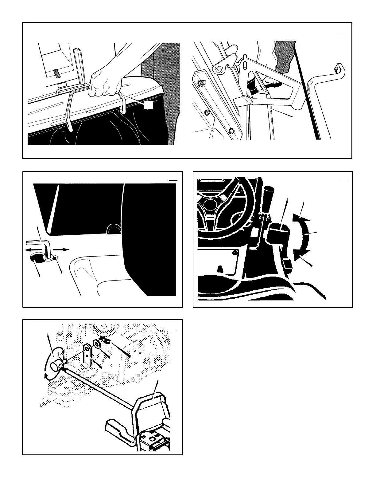
How To Empty The Grass Bagger
(Figure 32)
1. Move the blade rotation control to the DISENGAGED position.
2. While sitting on the seat, lift and pull the
handle (1) forward to the DUMP position.
3. Drive slowly forward to allow the grass to fall
out of the bag.
4. Push the handle rearward and down to the
OPERATING position.
NOTE: If the engine stops when you engage
the blade(s), the seat switch is not activated
or the grass bagger is not locked in place.
Before Starting The Engine
Check the oil
NOTE: The engine was shipped from the factory filled with oil. Check the level of the oil.
Add oil as needed. See the engine manufacturer’s instructions for the type of petrol and
oil to use.
1. Make sure the unit is level.
NOTE: Do not check the level of the oil
while the engine runs.
2. Check the oil. Follow the procedure in the
engine manufacturer’s instructions.
3. If necessary, add oil until the oil reaches the
FULL mark on the dipstick. The quantity of oil
needed from ADD to FULL is shown on the
dipstick. Do not add too much oil.
Add Petrol
WARNING: Always use a safety
petrol container. Do not smoke
when adding petrol to the fuel tank.
Do not add petrol when you are inside an
enclosure. Before you add petrol, stop the
engine and let the engine cool for several
minutes.
(Figure 9)
position with regular unleaded petrol. Do not use
premium unleaded petrol. Make sure the petrol is
fresh and clean. Leaded petrol will increase
deposits and shorten the life of the valves.
How To Start The Engine
the seat. These components tell the
electrical system if the operator is sitting
on the seat. This system will stop the
engine when the operator leaves the seat if
the blade rotation control is engaged or if
the transmission is engaged. For your
protection, always make sure this system
operates correctly.
NOTE: The engine will not start unless you
depress the brake pedal or engage the
parking brake and move the blade rotation
control to the DISENGAGE position.
1. Push the brake pedal completely forward.
2. Make sure the blade rotation control is in the
3. Move the throttle control completely forward
Fill the fuel tank (1) to the FULL (2)
WARNING: The electrical system
has an operator presence system
that includes a sensor switch for
Keep your foot on the pedal.
DISENGAGE position.
to the CHOKE or FAST position. Some models have a separate choke knob. Pull the
choke knob to the full CHOKE position.
Page 17

4. Turn the ignition key to the START position.
NOTE: If the engine does not start after
four or five tries, move the throttle control
to the FAST position. Again try to start the
engine. If the engine will not start, see the
TROUBLE SHOOTING CHART.
5. Slowly move the throttle control to the SLOW
position.
6. To start a hot engine, move the throttle control to a position between FAST and SLOW.
Mowing And Bagging Tips
1. For a lawn to look better, check the cutting
level of the mower housing. See “How To
Level The Mower Housing” in the Maintenance section.
2. For the mower housing to cut level, make
sure the tyres have the correct amount of air
pressure.
3. Every time you use the unit, check the blade.
If the blade is bent or damaged, immediately
replace the blade. Also, make sure the nut
for the blade is tight.
4. Keep the blade(s) sharpened. Worn blades
will cause the ends of the grass to turn
brown.
5. Do not cut or bag grass that is wet. Wet
grass will not discharge correctly. Let the
grass dry before cutting.
6. If the grass is very high, cut two times to decrease the load on the engine. First cut with
the mower housing in the highest position
and then lower the mower housing for the
second cut.
7. Operate the engine with the throttle in FAST
position and the shift lever in first or second
gear.
8. After each use, clean the bottom and top of
the mower housing for better performance.
Also, a clean mower housing will help prevent a fire.
MAINTENANCE
NOTE: Illustrations and pictorials begin on
page 2.
General Recommendations
1. The owner’s responsibility is to maintain this
product. This will extend the life of the product and is also necessary to maintain warranty coverage.
2. Check the spark plug, drive brake, lubricate
the unit, and clean the air filter once a year.
3. Check the fasteners. Make sure all fasteners
are tight.
4. Follow the Maintenance section to keep the
unit in good operating condition.
WARNING: Before you make an inspection, adjustment, or repair to
the unit, disconnect the wire to the
spark plug. Remove the wire from the
spark plug to prevent the engine from
starting by accident.
NOTE: Torque is measured in foot pounds
(metric Nm). This measurement describes
how tight a nut or bolt must be. The torque is
measured with a torque wrench.
F–000794J
Inspect Blade
hits an object, stop the engine. Check the
unit for damage. The blade has sharp
edges. When you hold the blade, use
gloves or cloth material to protect your
hands.
If you keep the blade (1) sharp and inspect the
blade for damage, the blade will cut better and be
more safe to operate. Frequently check the blade
for excessive wear, cracks, or other damage.
Frequently check the nut (3) that holds the blade
(1). Keep the nut (3) tight. If the blade hits an
object, stop the engine. Disconnect the wire to the
spark plug. See if the blade is bent or damaged.
Check the blade adapter (5) for damage. Before
you operate the unit, replace damaged parts with
original equipment parts. See the authorized
service centre in your area. Every three years,
have an authorized service person inspect the
blade or replace the old blade with an original
equipment part.
(Figure 10)
WARNING: Before you inspect or
remove the blade, disconnect the
wire to the spark plug. If the blade
How To Remove And Install The Blade
(Figure 10)
1. Remove the mower housing. See the instructions on “How To Remove The Mower Housing”.
2. Use a piece of wood to keep the blade from
rotating.
3. Remove the nut (3) that holds the blade (1).
4. Check the blade (1) and the blade adapter
(5) according to the instructions for “Inspect
Blade”. Replace a badly worn or damaged
blade with an original equipment blade. See
an authorized service centre in your area.
5. Clean the top and bottom of the mower housing. Remove all the grass and debris.
6. Mount the blade (1) and blade adapter (5)
on the mandrel (6).
7. Mount the left blade (1) and the right blade
(1) so that the hi–lift edges (7) are up. If the
blade is upside down, the blade will not cut
correctly and can cause an accident.
8. Fasten the blade (1) with the original
washers (2,8) and nut (3). Make sure the
outside rim of the Belleville washer (2) is
against the blade (1).
WARNING: Always keep the nut (3)
tight that holds the blade (1). A
accident.
9. Tighten the nut (3) that holds the blade (1) to
10.Install the mower housing. See “How To Re-
loose nut or blade can cause an
a torque of 45 foot pounds (62 Nm).
move The Mower Housing”.
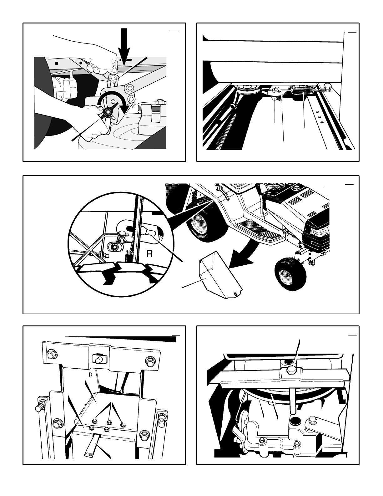
How To Adjust The Blade Rotation
Control
WARNING: To prevent an injury, the
blade rotation control must operate
correctly.
In normal usage, the blade rotation control will not
require an adjustment. However, if the cutting
performance decreases or the quality of cut is
poor, make the following changes.
1. When you mow, make sure the throttle control is in the FAST position.
17
GB
2.
(Figure 11
to the DISENGAGE position (1).
3. Stop the engine. Disconnect the wire from
the spark plug.
4. Check the blade(s). Keep a sharp edge on
the blade(s). A blade that is not sharp will
cause the tips of the grass to become brown.
5.
(Figure 12)
spring (2) from the blade control rod (1).
Move the blade drive spring (2) to the
middle hole (4). This will increase the ten-
sion on the mower drive belt.
6. Attach the wire to the spark plug. Mow for a
short distance and again check the quality of
cut. If necessary, move the blade drive
spring (2) to the bottom hole (5)
7. Again check the quality of cut. If the quality of
cut has not improved, replace the mower
drive belt. See “How To Replace The Mower
Drive Belt”. If the replacing the belt does not
correct the problem, take the unit to an authorized service centre.
8. Move the blade rotation control to the DISENGAGE position. Stop the engine.
9.
(Figure 13)
brake. Rotate the pulleys with your hand.
Make sure the brake pads (12) are pressed
tightly against the pulleys
ized service centre.
10.
(Figure 11)
to the ENGAGE position (2).
11.
(Figure 13)
brake (12). If the pads are excessively worn
or damaged, replace the brake pad assemblies. Correct replacement parts and assistance are available from an authorized
service centre.
12.Attach the wire to the spark plug. Mow for a
short distance and again check the operation
of the blade rotation control.
13.When you move the blade rotation control to
the DISENGAGE position, all movement will
stop within five seconds. If there is movement of the belt or the blades continue to rotate, engage and disengage the blade
rotation control five times to remove any excess rubber from a new mower drive belt. If
you need assistance, take the unit to an
authorized service centre.
14.
(Figure 12)
belt, move the blade drive spring (2) to the
top hole
How To Adjust The Speed Control Pedal
(Figure 37)
If the unit will not go into REVERSE or if the unit
moves very slowly in REVERSE, adjust the speed
control pedal as follows.
1. Stop the engine.
2. Set the parking brake.
3. Remove the hair pin (2) from the adjuster
nut (1). Disconnect the adjuster nut (1) from
the transaxle lever (3).
4. Rotate the adjuster nut (1)
direction shown in Figure 37.
NOTE: Too much adjustment will cause
REVERSE speed to be too fast and the
FORWARD speed to be reduced.
5. Attach the adjuster nut (1) to the transaxle
lever (3) with the hair pin (2).
) Move the blade rotation control
Disconnect the blade drive
Check the operation of the blade
WARNING: If the brake pads (12) do
not press tightly against the
pulleys, take the unit to an author-
Move the blade rotation control
Check the pads for the blade
If you replace the mower drive
(3).
one turn
in the
Page 18

6. To check the adjustment, drive the unit. If the
adjustment is correct, the unit will now go
into REVERSE.
IMPORTANT: If you need assistance, go to
the nearest Authorized Service Centre. They
have the equipment and experience to make
the adjustment.
How To Check And Adjust The Motion
Drive Belt
If the motion drive belt is loose, the belt will slip
when; going up a hill, pulling a heavy load, or the
unit will not move forward.
IMPORTANT: Always operate with the engine
speed in the FAST position. If the engine
speed is in a slow or moderate position, the
engine and transmission can become too hot
and cause problems that are similar to a
loose motion drive belt.
spark plug. Remove the wire from the
spark plug to prevent the engine from
starting by accident.
1. Check the routing of the motion drive belt.
Make sure the belt is installed correctly and
is inside all the belt guides.
2. Disconnect the adjustable nut (1) from the
motion drive idler assembly (2).
3. Pull the clutch rod (3) until tight. Turn the
adjustable nut (1) until the nut will fit through
the hole in the motion drive idler assembly
(2).
4. Remove the adjustable nut (1) from the
hole. To lengthen the clutch rod (3), rotate
the adjustable nut (1) 3 to 4 turns counter–
clockwise.
5. Assemble the adjustable nut (1) to the mo-
tion drive idler assembly (2).
6. If the belt still slips after the belt has been
adjusted, then the motion drive belt is worn
or damaged and must be replaced. See
“How To Replace The Motion Drive Belt”.
(Figure 24)
WARNING: Before you make an inspection, adjustment, or repair to
the unit, disconnect the wire to the
How To Check And Adjust The Drive
(Figure 15)
Brake
Completely push the brake pedal forward. Set the
parking brake. Push the unit. If the rear wheels
rotate, adjust or replace the brake pads. Adjust the
drive brake (1) as follows.
1. The location of the drive brake (1) is on the
side of the gearbox (3).
2. Make sure the parking brake is set. Turn the
hex nut (2) in a clockwise direction until the
rear wheels do not turn when the unit is
pushed forward.
3. Release the parking brake and push the unit.
If the unit does not roll, turn the hex nut (2)
in a counter–clockwise direction until the unit
rolls.
4. Set the parking brake. Push the unit. If the
rear wheels do not turn, the drive brake (1)
is correctly adjusted. Release the parking
brake.
WARNING: If you cannot correctly
adjust the drive brake, replace the
brake pads. Correct replacement
parts and assistance are available from an
authorized service centre.
F–000794J
How To Remove The Battery
To charge or clean the battery (1), remove the
battery (1) from the unit as follows.
WARNING: To prevent sparks, disconnect the black battery cable (8)
from the negative (–) terminal be-
fore you disconnect the red cable (5).
WARNING: The battery contains
sulphuric acid which is harmful to
the skin, eyes and clothing. If the
acid gets on the body or clothing, wash
with water.
1. Remove the battery cover (3).
2. Remove the fasteners (9) from the battery
brackets (10,11).
To prevent sparks, do not touch
battery brackets to terminals.
3. Apply pressure to the left hand battery
bracket (10) and remove bracket from frame
(12) as shown.
4. Remove the right hand battery bracket
(11).
5. Disconnect the black cable (8) from the
negative (–) terminal.
6. Disconnect the red cable (5) from the posi-
tive (+) terminal (4).
7. Lift the battery (1) out of the unit.
How To Charge The Battery
WARNING: When you charge the
battery, do not smoke. Keep the
battery away from any sparks. The
fumes from the battery acid can cause an
explosion.
1. Before you charge the battery (1), remove
the battery (1).
2. To charge the battery (1), use a 12 volt battery charger. Charge at a rate of 6 amperes
for 1 hour.
3. Install the battery (1).
WARNING: To prevent sparks,
fasten the red cable to the positive
(+) terminal before you connect the
black cable.
4. Fasten the red cable (5) to the positive (+)
terminal (4) with the fasteners as shown.
Slide the terminal cover (2) over the posi-
tive terminal (4).
5. Fasten the black cable (8) to the negative
(–) terminal with the fasteners as shown.
(Figure 6
(Figure 6)
)
How To Level The Mower Housing
(Figure 16 and Figure 17)
If the mower housing is level, the blade will cut
easier and the lawn will look better.
WARNING: Before you make an inspection, adjustment, or repair to
spark plug. Remove the spark plug wire to
prevent the engine from starting by accident
1. Make sure the unit is on a hard flat surface.
2. Check the air pressure in the tyres. If the air
3. If equipped, remove the gauge wheels.
the unit, disconnect the wire to the
pressure is incorrect, the mower housing will
not cut level. The correct air pressure is:
Front Tyres 1,38 BAR (20 PSI), Rear Tyres
0,97 BAR (14 PSI).
18
GB
4.
(Figure 16)
level adjustment position (2).
justment position (2).
5.
(Figure 17)
juster knobs (1). Push down on each side of
the mower housing. Make sure both sides of
the mower housing are setting on a flat surface. Also, make sure the lift links (2) are
loose and can easily move up or down
6. Push down on the lift links (2) and tighten
the left and right adjuster knobs (1). If
necessary, use a wrench to tighten the ad-
juster knobs (1)
7.
(Figure 16)
8. If equipped, attach the gauge wheels.
9. Mow for a short distance. If the height of cut
is not level, repeat the above steps.
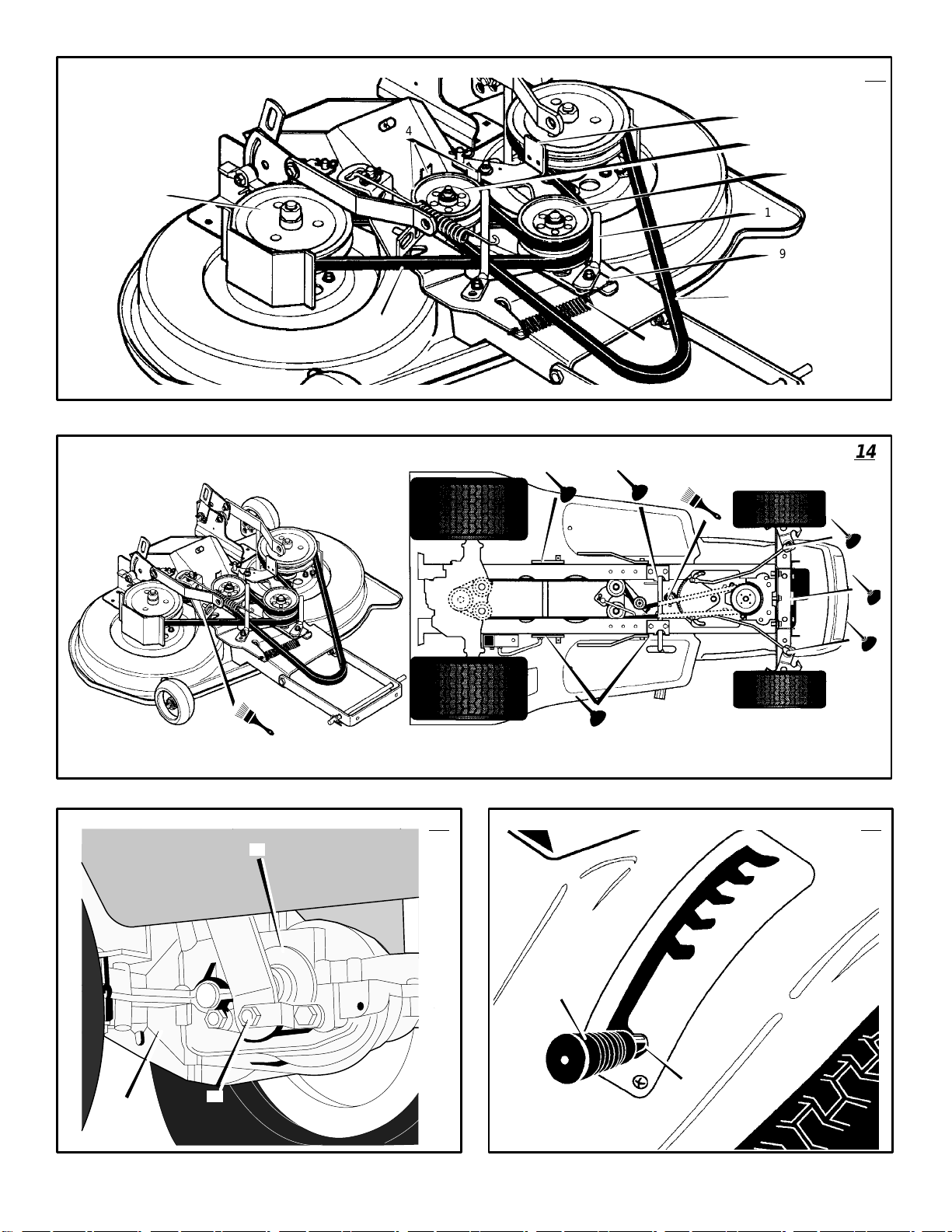
Where To Lubricate
NOTE: Apply grease to the steering gear assembly.
CAUTION: If the unit is operated in dry areas
that have sand, use a dry graphite spray to
lubricate the unit.
Check The Tyres
Check the air pressure in the tyres. Tyres with too
much air pressure will cause the unit to ride rough.
Also, the wrong air pressure will keep the mower
housing from cutting level. The correct air
pressure is: Front Tyres 1,38 BAR (20 PSI), Rear
Tyres 0,97 BAR (14 PSI).
How To Replace The Motion Drive Belt
1. Remove the mower housing. See the instructions on “How To Remove The Mower Housing”.
2.
(Figure 19)
hold each side of the middle discharge
chute (2). Remove the middle discharge
chute (2)..
3.
(Figure 18)
spring (1).
4.
(Figure 23)
(2).
5.
(Figure 18)
from the idler bracket (4).
6.
(Figure 20)
from the transaxle sheild (2). Place the
transaxle shield (2) in the tunnel (3). The
bag full indicator (4) wire harness will limit
the transaxle sheild (2) movement.
7.
(Figure 21)
drive pulley (3).
8. Remove the motion drive belt (4) from the
drive pulley (3).
9.
(Figure 22)
(1) from the stack pulley (2), pull the front
end of the belt under the stack pulley (2)
Move the lift lever (1) to the
WARNING: The lifter lever (1) is
spring loaded. Make sure the lift
lever (1) is locked in the level ad-
Loosen the left and right ad-
Raise the lift lever (1).
(Figure 14)
Models with grease fittings:
Lubricate with grease gun.
Apply grease with a brush to
the areas shown.
Lubricate the areas shown
with engine oil.
Remove the screws (1), that
Disconnect the belt tension
Remove the three idler pulleys
Remove the adjuster nut (3)
Remove the three screws (1)
Loosen the belt guide (1) at the
To remove the motion drive belt
Page 19

and then back between the stack pulley and
the steering plate (3).
10.Remove the motion drive belt. A correct replacement part or assistance is available
from an Authorized Service Centre in your
area.
11.To install the motion drive belt, reverse the
above steps.
12.
(Figure 23)
drive belt (1). Make sure the motion drive
belt is installed correctly on the idler pulleys
(2).
Check the routing of the motion
How To Replace The Mower Drive Belts
(Figure 13)
1. Remove the mower housing. See the instructions on “How To Remove The Mower Housing”.
2. Loosen and pull the belt retainer (1) away
from the double idler pulley (2). Remove
the primary mower drive belt (3) from the
double idler pulley (2).
3. Pull the belt retainers (4) away from the
single idler pulley (5). Remove the primary
mower drive belt (3) from the single idler
pulley (5).
4. Remove the primary mower drive belt (3)
from the mower housing.
5. To release tension on the secondary belt,
remove the spring (8) from the double idler
mount (9).
6. Remove the secondary mower drive belt
(10) from the double idler pulley (2) and
from the right mandrel pulley (11).
7. A correct replacement part or assistance is
available from an Authorized Service Centre
in your area.
8. To install the mower drive belt, reverse the
above steps.
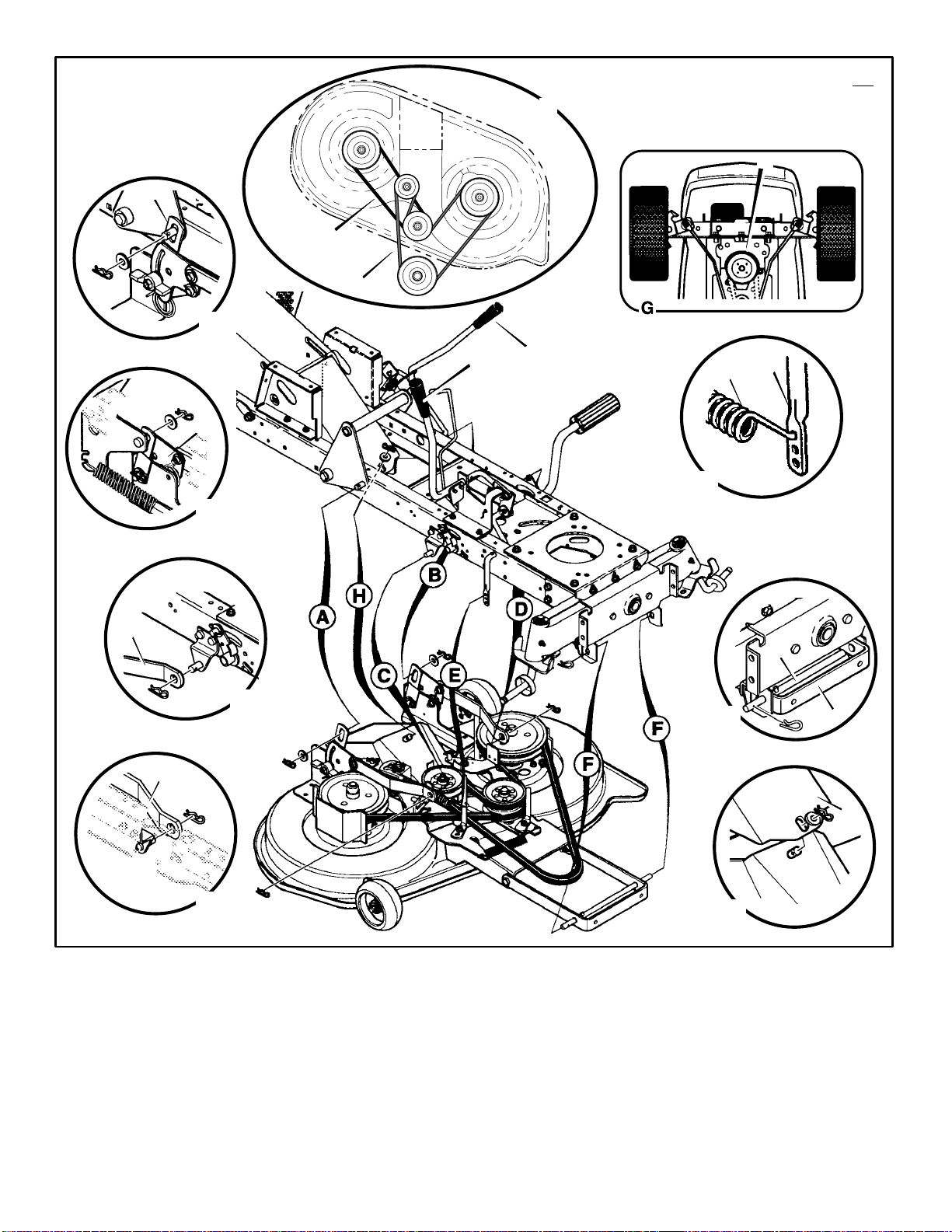
How To Remove The Mower Housing
(Figure 38)
1. Move the blade rotation control (1) to the
DISENGAGE position.
2. Move the lift lever (2) to the level adjustment position.
3. Remove the hair pins and the washers from
the adjuster arms (3). See illustrations “C”
and “D”.
4. Remove the hair pins and washers from the
suspension links (4). See illustrations “A”
and “B”.
5. Disconnect the extension spring (5) from
the blade control rod (6). See illustration
“E”.
6. Disconnect the front hanger (9) from the
axle support. See illustration “F”.
NOTE: The hanger rod (11) is made with a
bend.
7. Remove the mower drive belt (7) from the
stack pulley (8). See illustration “G”.
8. Disconnect the middle discharge chute
(10) from the mower housing. See illustration
“H”.
9. Pull the mower housing away from the right
side of the unit.
10.To install the mower housing, reverse the
above steps.
11.Check belt routing of the primary mower
drive belt (1) and the secondary mower drive
belt (2). See illustration “J”.
How To Replace The Fuse
If the fuse is blown, the engine will not start.
Remove the fuse and replace with a 15 amp.
automotive fuse.
Storage (over 30 days)
At the end of each year, prepare the unit for
storage as follows.
1. Drain the fuel from the carburettor and the
fuel tank. Change the engine oil. See the engine manufacturer’s instructions.
2. Clean the entire unit.
3. Charge the battery.
GB
WARNING: Never store the grass
bagger with grass clippings in the
bags. Even a small amount of
grass or debris can generate enough heat
to start a fire.
WARNING: Do not operate unless
the entire grass bagger attachment
is in place.
How To Order Replacement Parts
Use only manufacturer’s authorized or approved
replacement parts. The letter placed on the end of
the part number denotes the type of finish for the
part, C for chrome, Z for zinc, a PA for purchased
assembly. It i s important that you include this when
ordering a part. Do not use attachments or
accessories not specifically recommended for this
unit. In order to obtain proper replacement parts
you must supply the model number of your mower
(see nameplate).
Replacement parts, except for the engine, transmission, transaxle or differential, are available
from the store where the mower was purchased or
a service shop recommended by the store.
If you are unable to obtain parts or service in the
manner outlined above, then contact:
HAYTER LIMITED, Service Department, Spellbrook, Bishop’s Stortford, Hertfordshire.
CM23 4BU.
UK ONLY : Details of your local Hayter authorised
dealer are contained in Yellow Pages or contact:
Freephone 0800 616298.
Replacement parts for the engine, transaxle, or
transmission, are available from the manufacturer’s authorized service centre found in the commercial pages of the telephone directory. Also, see
the individual engine or transmission warranties to
order replacement parts.
When ordering the following information is
required:
(1) The Model Number
(2) Serial Number
(3) Part Number
(4) Quantity
F–000794J
19
Page 20

TROUBLE SHOOTING CHART
PROBLEM: The engine will not start.
1. Follow the steps, “How To Start The Engine”
in this book.
2. Electric–Start Models: Clean the battery terminals. Tighten the cables.
3. Check for a loose wire. Tighten the limit
switches. (See the wiring diagram.)
4. Drain the fuel tank. Clean the fuel line. Replace the fuel filter.
5. Remove the spark plug(s). Move the throttle
to the SLOW position. Turn the ignition key to
the ON position. Try to start the engine several times. Install the spark plug.
6. Replace the spark plug.
7. Adjust the carburettor.
PROBLEM: The engine will not turn
over.
1. Follow the steps, “How To Start The Engine”
in this book.
2. Electric–Start Models: Check the level of the
acid in the battery. If needed, add water.
Charge the battery.
3. Replace the fuse.
4. Check the wiring harness for damage or a
loose connection. Repair the damaged wire.
5. Electric–Start Models: replace the solenoid.
Recoil–Start Models: replace the module.
PROBLEM: The engine does not run
smooth at fast speed.
1. Replace the spark plug.
2. Adjust the throttle control.
3. Clean the air filter.
4. Replace the fuel filter.
PROBLEM: The engine stops when the
blades are engaged.
1. To activate the seat sensor, always sit in the
middle of the seat.
2. Check the wiring harness for damage or a
loose connection. Repair the damaged wire.
3. Grass Bagger not closed properly. (only
applies to rear grass baggers.)
PROBLEM: On slopes, the engine
stops.
1. Mow up and down slopes. Never mow
across a slope.
2. To activate the seat sensor, always sit in the
middle of the seat.
PROBLEM: The engine will not idle.
1. Replace the spark plug.
2. Clean the air filter.
3. Adjust the carburettor.
4. Adjust the throttle control.
5. Drain the fuel tank. Clean the fuel line. Replace the fuel filter.
GB
2. Raise the height of cut.
3. Replace or sharpen the blade(s).
4. Move the shift lever to a slower speed.
5. Move the throttle control to the FAST position.
6. Replace the spring for the blade idler.
PROBLEM: The mower housing does
not cut level.
1. Check the air pressure in the tyres.
2. Adjust the level of the mower housing.
3. Check the front axle. If the front axle does
not freely pivot, loosen the axle bolt(s).
PROBLEM: The mower blades will not
rotate.
1. Check the mower drive belt. Make sure the
belt is installed correctly.
2. Replace the mower drive belt.
PROBLEM: The unit will not move when
the brake is released and the speed
control pedal is depressed.
1. Check the motion drive belt. Make sure the
belt is installed correctly.
2. Adjust the clutch.
3. Replace the motion drive belt.
4. Release the Automatic Drive Disconnect
under the seat.
PROBLEM: The engine is difficult to
start.
1. Adjust the carburettor.
2. Replace the spark plug.
3. Replace the fuel filter.
PROBLEM: The engine does not run
smooth or has a loss of power.
1. Check the oil.
2. Clean the air filter.
3. Clean the air screen.
4. Replace the spark plug.
5. The engine is working too hard. Use a slower
speed.
6. Adjust the carburettor.
7. Replace the fuel filter.
PROBLEM: A hot engine causes a decrease in power.
1. Clean the air screen.
2. Check the oil.
3. Adjust the carburettor.
4. Replace the fuel filter.
PROBLEM: Excessive vibration.
1. Replace the blade.
2. Check for loose engine bolts.
3. Decrease the air pressure in the tyres.
4. Adjust the carburettor.
5. Check for a damaged belt or damaged
pulley. Replace the damaged parts.
PROBLEM: The grass does not discharge correctly.
1. Stop the engine. Clean the mower housing.
PROBLEM: The unit moves slower or
stops when the speed control pedal is
depressed.
1. Adjust the clutch.
2. Replace the motion drive belt.
PROBLEM: When the brake pedal is released, belt noise can be heard.
1. Temporary belt noise does not change the
operation of the unit. If belt noise is continuous, check the routing of the belt. Make sure
the belt is inside all belt guides.
2. If the noise is continuous, adjust the clutch.
PROBLEM: The rear wheels spin over
uneven terrain.
1. Check the front axle. If the front axle does
not freely pivot, loosen the axle bolt(s).
F–000794J
20
Page 21

NOTES
F–000794J
21
Page 22

REPAIR PARTSCODE145S
CHASSIS & HOOD ASSEMBLY
34
46
51
33
50
26–4
36
35
49
44
26–4
26–3
32
26–4
48
26–4
47
26
27
15
19
26–3
48
26–1
17
13
21
12
22
16
20
14
10
8–2
8
8–1
REF.
CHASSIS REAR PG.
(SEAT DECK ASSY.)
EDGE TO OUTSIDE
REF.
KEY#17
NOTE
MOUNT KEY# 17 WITH EDGE FACING OUTSIDE HOOD.
23
18
5
42
40
1
2
7
6
41
F–000794J
345105A
22
Page 23

REPAIR PARTSCODE145S
CHASSIS & HOOD ASSEMBLY
Key
No. Description Part No.
1 Bracket, Grille RH MU69011–853
2 Screw, 5/16–18x1.50 MU711653
5 Grille MU94455–848
6 Nut, “J” Tinnerman MU710313
7 Screw, 1/4–20x.63 MU711642
8 Lens & Reflector MU95234
8–1 Lens MU94459
8–2 Reflector MU94460
10 Screw, 1/4–14x.50 MU710197
12 Hood Asm. MU690052–848
13 Panel, Side RH MU94458–848
Key
No. Description Part No.
26–2 Bracket, LH MU94465
26–3 Bracket, RH MU94464
26–4 Screw, 10–24x.500 MU710196
27 Screw, 5/16–18x.75 MU711606
32 Dash MU690110
33 Screw, 10–24x.500 MU711629
34 Screw, 10–24x.500 MU711629
35 Steering Bracket MU94075
36 Screw, 1/4–14x.50 MU710197
40 Strut, Grille MU94519–848
41 Screw, 1/4–20x.50 MU711642
14 Panel, Side LH MU94457–848
15 Bolt, HHSH 3/8–16 MU711625
16 Washer, Plastic MU710067
17 Pivot Base MU690114
18 Nut, 3/8–16 MU711622
19 Pivot Cap MU690113
20 Quick Release MU94474
21 Spring, Comp. MU710314
22 Nut, Wing MU325232
23 Screw, 1/4–20x1.25 MU313674
26 Console Asm. MU95291–848
26 Console Asm. MU95291–848
42 Speed Nut MU711652
44 Lanyard Hood MU643129
45 Nut, 1/4–20 MU73826
46 Screw, 1/4–20x.63 MU711674
47 Nut, “J” Tinnerman MU710313
48 Trim 9.50 Inches MU55021
49 Trim, 26.80 Inches MU55021
50 Access Panel MU95366–848
51 Screw, 10–24x.500 MU711629
–– Decal, Hayters 15/40 RH MU712184
–– Decal, Hayters 15/40 LH MU712183
–– Instruction Book & Parts List MUF–000794J
26–1 Lower Console MU95173
F–000794J
23
Page 24

30
REPAIR PARTSCODE145S
REAR CHASSIS ASSEMBLY
20–2
REF .
ELECTRICAL PG.
(TAPE SWITCH)
12
12
5
14
(4–1)
4
21
81
90
16
7
12
12
25
19
20–3
80
7
31
22
7
17
26
31
20
(20–1)
15
13
18
4–3
13
4–4
7
24
27
29
REF.
FINAL ASSEMBLED DECK PG.
(MOWER DECK)
91
4–2
344862B
F–000794J
15
13
8
9
SUB ASSY. FRAME PG.
REF.
(FRAME ASSY .)
6
7
23
344862A
24
Page 25

REPAIR PARTSCODE145S
REAR CHASSIS ASSEMBLY
Key
No. Description Part No.
4 Assy., Back Plate/Battery MU343678–853
4–1 Assy. Back Plate Flat MU95162
4–2 Battery Tray Assembly MU94563
4–3 Screw, 5/16–18x.50 MU180073
4–4 Nut, 5/16–18 Hexwdfllk MU45174
5 Weldment–Latch Lever MU95359–853
6 Rod, Brace MU690097
7 Nut, 3/8–16 Hwdfl Whiz–lock MU711906
8 Rod, Brace MU94231
9 Screw, 5/16–18x.75 MU711606
12 Screw, 5/16–18x.75 MU9357
Key
No. Description Part No.
20 Asm., T/A Shield & Chute MU690102–853
20–1 Chute Weld Asm. Upper MU94350
20–2 Shield, Transaxle MU95367
20–3 Screw, 1/4–20x.63 MU711642
21 Screw, 5/16–18x.75 MU711606
22 Bolt, Carriage 5/16–18x.75 MU340720
23 Nut, 5/16–18 MU710026
24 Middle Chute Assembly MU94296–853
25 Shoulder Bolt MU009x57
26 Flap, Chute MU94264
27 Fastener, Ratchet MU309235
13 Nut, 5/16–18 Hexwdfllk MU710026
14 Screw, 5/16–18x.75 MU711606
15 Nut, 5/16–18 Hexwdfllk MU710026
16 Bracket, Flex Switch Mting MU690245
17 Wire Clip, Adhesive MU55939
18 Flatwasher MU711666
19 Pad, Adhesive MU318197
29 Pin, Hair MU711682
30 Bolt, Carriage 5/16–18x.75 MU340720
31 Nut, 5/16–18 MU710026
80 Tape, Dble Sided Foam 3/4” MU712009
81 Tape, Dble Sided Foam 3/4” MU712009
90 Screw, 1/4–20x.63 MU711642
91 Cable Tie MU57444
F–000794J
25
Page 26

CUSTOMER
SPEC PAGE
REPAIR PARTSCODE145S
REAR CHASSIS ASSEMBLY
38
45
100
44
43
39
CUSTOMER
SPEC PAGE
42
53
35
36
84
37
85
CUSTOMER
SPEC PAGE
82
52
34
84
83
40
41
CUSTOMER
SPEC PAGE
45
46
48
47
49
2
84
3
75
75
33
F–000794J
74
NOTE
74
344862B
26
Page 27

REPAIR PARTSCODE145S
REAR CHASSIS ASSEMBLY
Key
No. Description Part No.
2 Plate, Lift Detent MU95190–853
3 Screw, #12x.50 MU711741
33 Screw, 5/16–18x.75 MU711606
34 Spring, Compression MU710136–853
35 Shoulder Bolt 1/4–20 MU711610
36 Zinc Washer Cup MU95293
37 Nut, 1/4–20 Centerlock MU302635
38 Cover, Battery MU94200
39 Support, Seat MU94154–848
40 Spring–Leaf MU94057
41 Screw, 1/4–20x.50 MU711592
Key
No. Description Part No.
45 Nut, Push Cap MU711627
46 Battery Bracket, LH MU95393–853
47 Battery Bracket, RH MU95394–853
48 Bolt, Carriage 1/4–20x.63 MU711680
49 Nut, Wing 1/4–20 MU711636
52 Washer, Flat MU711644
53 Bolt, Wing 5/16–18x.50 MU711747
74 Nut, 5/16–18 MU710026
75 Bolt, Carriage 5/16–18x.75 MU711891
82 Seat Deck Pedal MU94311–848
83 Bracket, Pivot Seat MU94153–848
42 Spring, Compression MU710109–853
43 Screw, 5/16–18x.75 MU711606
44 Hinge Seat Pivot MU95294
84 Screw, 5/16–18x.75 MU711606
85 Nut, 5/16–18 MU711634
100 Trim 41.00 Inches MU55021
F–000794J
27
Page 28

REPAIR PARTSCODE145S
GRASS BAGGER ASSEMBLY
73
72
54
104
89
REF.
DETAIL ’A’
87
57
87
101
97
56
59
102
62
71
89
87
69
86
61
67
88
68
58
DETAIL ’A’
55
58
57
59
64
63
64
70
61
64
62
60
66
103
344862B
F–000794J
28
Page 29

REPAIR PARTSCODE145S
GRASS BAGGER ASSEMBLY
Key
No. Description Part No.
54 Asm. Weld Upper Frame MU690044–853
55 Spring, Torsion RH MU690003
56 Spring, Torsion LH MU690004
57 Bracket, Spring Collector MU95339–853
58 Screw, 1/4–20x.50 MU313686
59 Nut, 1/4–20 MU73826
60 Brace, Frame Collector MU94850–853
61 Screw, 1/4–20x.62 MU711909
62 Nut, 1/4–20 MU711632
63 Asm. Support Collector MU95343–853
64 Screw, 1/4–20x1.50 MU711653
Key
No. Description Part No.
69 Top Collector Assembly MU94908–848
70 Handle, Dump Collector MU690019
71 Handle, Reba Collector MU690506–853
72 Reba Collector Bag MU95389
73 Rubber Grip MU94854
86 Washer MU712129
87 Washer MU711921
88 Nut, 1/4–20 Tinnerman MU578107
89 Screw, 1/4–20x.63 MU711674
97 Brace, Bagger MU690010–853
101 Screw, 1/4–20x1.50 MU712068
66 Asm. Front Frame Collect MU95349–853
67 Screw, 1/4–20x.62 MU711909
68 Nut, 1/4–20 MU711632
102 Nut, 1/4–20 MU711632
103 Screw, #12x.50 MU711741
104 Screw, #12x.50 MU711741
F–000794J
29
Page 30

REPAIR PARTSCODE145S
FRAME ASSEMBLY
34
6
8
12
10
5
35
7
38
4
3
41
11
1
14
17
13
39
9
2
37
40
32
29
43
44
45
37
21
33
19
32 16
30
31
20
26
18
15
36
23
36
24
27
28
343650A
F–000794J
30
Page 31

REPAIR PARTSCODE145S
FRAME ASSEMBLY
Key
No. Description Part No.
1 Frame, Rail RH MU94564
2 Frame, Rail LH MU94565
3 Support, Seat RH MU94634
4 Support, Seat LH MU94633
5 Screw, .312–18x.75 MU26X249
6 Brace, BackPlate RH MU94561
7 Brace, BackPlate LH MU94562
8 Screw, 5.312–18x.75 MU26X249
9 Bracket, Transaxle MU94008
10 Bracket, TA RH–VST LH–MS MU94234
11 Asm. Idler Mount Rear MU94236
Key
No. Description Part No.
23 Bracket, Hanger Rear MU94013
24 Screw, .312–18x.75 MU26X249
26 Gear, Sector MU94121
27 Bearing, Sector Gear MU94123
28 Screw, 5/16–18x1.00 MU001X84
29 Nut, 5/16–18 MU15X113
30 Clutch/Brake Pedal MU690033
31 Screw, .312–18x.75 MU26X249
32 Bracket, Suspension Asm. MU94285
33 Screw, .312–18x.75 MU26X249
34 Brace, Rail MU94566
12 Screw, .312–18x.75 MU26X249
13 Assy., Idler Mount, Front MU94237
14 Screw, .312–18x.75 MU26X249
15 Plate, Steering MU1001024
16 Screw, .312–18x.75 MU26X249
17 Crank, PTO MU690394
18 Bracket, Bell Crank MU94005
19 Screw, .312–18x.75 MU26X249
20 Washer, Flat MU120395
21 Bracket, Seat Deck RH MU690035
35 Screw, .312–18x.75 MU26X249
36 Zinc Screw Guide MU93349
37 Nut, 5/16–18 MU015X79
38 Bracket, Pivot MU94015
39 Washer, Flat MU845
40 Bolt, Shoulder 3/8–16 MU009X53
41 Nut, 3/8–16 MU015X84
43 Bracket, Seat Deck LH MU690036
44 Screw, .312–18x.75 MU26X249
45 Nut, 5/16–18 MU015X79
F–000794J
31
Page 32

REPAIR PARTSCODE145S
FRAME ASSEMBLY
SUB. ASSY. FRAME PG.
REF.
(SECTOR GEAR)
71
74
90
73
88
87
62
91
67
73
89
75
76
70
83
86
61
81
68
84
60
65
64
69
72
77
80
79
F–000794J
82
78
343650A
32
Page 33

REPAIR PARTSCODE145S
FRAME ASSEMBLY
Key
No. Description Part No.
60 Engine Plate MU94006
61 Screw, .312–18x.75 MU26X249
62 Nut, 5/16–18 MU015X88
64 Bracket, Muffler Mount MU94307
65 Screw, .312–18x.75 MU26X249
67 Nut, 5/16–18 MU015X79
68 Guide–Stack Pulley Belt MU94310
69 Zerk, Grease MU706
70 Axle, Cast Machined MU95405
71 Spindle, Long RH MU95182
72 Spindle, Long LH MU95183
Key
No. Description Part No.
77 Hanger, Axle MU94007
78 Hanger, Deck RH MU690199
79 Hanger, Deck LH MU690198
80 Screw, 5/16–18x3.00 MU180113
81 Nut, 5/16–18 MU015X88
82 Screw, .312–18x.75 MU26X249
83 Drag Link, LH MU95329
84 Drag Link, RH MU95328
86 Nut, 3/8–16 MU015X84
87 Shoulder Bolt MU009X57
88 Nut, 3/8–16 MU015X84
73 Bearing, Spindle MU92527
74 Washer, .766IDx1.62ID MU17X1 13
75 E–Ring MU0011X3
76 Washer, Flat MU17X195
89 Screw, 3/8–16x1.50 MU01X111
90 Flatwasher MU17X104
91 Flatwasher MU017X53
F–000794J
33
Page 34

REF.
CUSTOMER
SPEC PAGE
43
44
REPAIR PARTSCODE145S
STEERING
REF.
CUSTOMER
SPEC PAGE
26
28
31–2
34
29
30
27
SUB. ASSY. FRAME PG.
REF.
(FRAME)
9
31–3
F–000794J
35
31
31–4
31–3
31–1
344861A
34
Page 35

REPAIR PARTSCODE145S
STEERING
Key
No. Description
9 Dust Hub Cap MU094618
26 Shaft, Steering MU94520
27 Bearing–Lower MU94124
28 Screw, 5/16–18x.75 MU711606
29 Gear, Pinion MU94122
30 Retaining Ring MU710102
31 Tire & Rim MU692641
31–1 Valve Stem MU338512
31–2 Rim MU338517
31–3 Bearing MU338513
31–4 Tire MU338514
Part
No.
F–000794J
34 Flatwasher MU711758
35 E–Ring MU0011X3
43 Screw, 1/4–20x.75 MU711719
44 Flatwasher MU711663
–– Hub Cap MU094618
35
Page 36

REPAIR PARTSCODE145S
MOTION DRIVE
63
62
38
43
15
REF.
SUB. ASSY. FRAME PG.
(SUPPORT BRKT.)
71
4
47
5
6
12
14
64
61
SUB. ASSY. FRAME PG.
(FRAME ASSY .)
62
2
REF. KEY# 17
16
13
58
17
REF.
5
29
75
70
NOTE
18
28
KEY# 33 & 43 ARE MOUNTED WITH
HUB FACING DOWN.
44
66
67
REF.
CUSTOMER SPEC
PAGE
54
45
21
65
46
71
23
19
20
53
22
43
26
37
39
37
49
38
6
42
35
72
40
1
33
41
REF. KEY# 42
32
F–000794J
48
31
3
36
39
37
59
37
ENGINE & CONTROL PG.
55–355–2
9
CHASSIS FRONT PG.
68
REF.
(ENGINE PULLEY)
REF.
(SEAT DECK)
10
69
61
60
50
55–1
55
345098B
36
Page 37

Key
No. Description Part No.
1 Transaxle, VST205 *
REPAIR PARTSCODE145S
MOTION DRIVE
Key
No. Description Part No.
42 Belt, V 4L 112.75 MU94609
2 Screw, 5/16–18X2.50 MU711669
3 Nut, 5/16–18 MU711634
4 Bracket, Stabilizer MU94224–853
5 Screw, 5/16–18x1.00 MU711893
6 Screw, 5/16–18x.75 MU710268
9 Pedal Assy., Hydro MU690134–853
10 Rod, Foot Control MU690018
12 Bracket, Shift MU323212
13 Washer, Transaxle MU711895
14 Screw, 1/4–28x.75 MU01x145
15 Spring, Transaxle MU94622
16 Spring MU326780
17 Disconnect Bracket MU94621–853
18 Bolt, HHSH 5/16–18 MU711896
19 Spring, Brake MU95424
20 Washer, Flat MU711921
43 Pulley, Idler MU1001065
44 Rod–Parking Brake MU95108
45 Nut, 5/16–18 Adjusting MU711898
46 Extension Spring MU165x107
47 Adjusting Nut 1/2–13 MU711594
48 E–Ring MU0011X3
49 Pin, Hair MU711659
50 Pin, Hair MU711676
53 Pin, Cotter MU71081
54 Pin, Cotter MU71081
55 T ire & Rim MU692511
55–1 Valve Stem MU338512
55–2 Rim MU338524
55–3 Tire MU338525
58 Bracket, Stabilizer MU94225–853
59 Bolt, Carr. 5/16–18x.75 MU711688
21 Rod, Clutch MU690016
22 Pin, Clevis MU711903
23 Latch, Park Brake MU690048
26 Spring, Tension MU711522
28 Rod, Disconnect Ctrl MU690015
29 Grip, Hydro Disconnect MU690032
31 Screw, 3/8–16x1.25 MU711905
32 Key, Square MU52928
33 Pulley, Idler MU1001065
35 Assy, Idler Arm Traction MU94238–853
36 Washer, Flat MU711758
37 Washer, Flat MU711904
38 Screw, 3/8–16x1.25 MU711905
39 Spacer MU95274
40 Pulley, Idler MU690409
41 Nut, 3/8–16 MU711920
60 Nut, 5/16–18 MU710026
61 Flatwasher MU711894
62 Nut, 1/4–20 MU710026
63 Screw Guide MU711745
64 Nut, 5/16–18 MU710026
65 Screw, 1/4–20x.50 MU313686
66 Retainer, Wire MU711742
67 Nut, 1/4–20 MU780285
68 Pad, Speed Ctrl Pedal MU94798
69 Pad, Toe Sandpaper MU93249
70 Pushnut MU711691
71 Washer, Flat MU71067
72 Spacer 1/2 to 17MM MU690369
75 Parking Brake Knob MU95315
–– Hubcap MU094618
* Contact your nearest transaxle dealer for parts and service.
For information on Replacement Parts see the Central Parts Distributor in your area.
F–000794J
37
Page 38

REPAIR PARTSCODE145S
MOWER SUSPENSION ASSEMBLY
25
26
28
SUB. ASSY. FRAME PG.
REF.
(CONTROL ARM)
20
18
21
16
1
19
15
17
24
31
16
32
35
34
38
33
3
40
2
41
36
37
34
33
10
4
5
6
29
30
SUB. ASSY. FRAME PG.
REF .
(FRAME ASSY .)
F–000794J
27
REF.
FINAL ASSEMBLED DECK PG.
(LIFT ARM)
9
REF .
FINAL ASSEMBLED DECK PG.
(SPRING)
344419A
38
Page 39

REPAIR PARTSCODE145S
MOWER SUSPENSION ASSEMBLY
Key
No. Description Part No.
1 Assembly, Lift Arm MU95233–853
2 Screw, 1/2–13x1.50 MU711917
3 Nut, 1/2–13 Lock MU711918
4 Bracket. Lift Link MU94262–853
5 Washer, Flat MU711617
6 Hair Pin MU711676
9 Hair Pin MU711676
10 Spring, Extension MU710235
15 Link–Lift Handle MU711981
16 Washer, Flat MU711617
17 Hair Pin MU711676
Key
No. Description Part No.
25 Grip MU94496
26 PTO Handle MU690126
27 Paddle, Switch MU95284
28 Screw, Thread Form MU711621
29 Bracket, PTO MU94018–853
30 Screw, 5/16–18x.50 MU780055
31 Lever, PTO MU95283
32 Bolt, Shoulder 3/8–16 MU711613
33 Hair Pin MU711659
34 Washer, Flat MU711615
35 Link PTO MU95282
18 Handle, Lift MU690532
19 Torsion Spring MU710111
20 Hair Pin MU711676
21 Grip, Lift MU94497
24 Washer, Flat MU711616
36 Nut, 3/8–16 MU711622
37 Screw 5/16–18x.75 MU711606
38 Torsion Spring MU710141
40 Spacer MU94309
41 Spacer, Sleeve MU56150
F–000794J
39
Page 40

39
REPAIR PARTSCODE145S
ENGINE AND CONTROL ASSEMBLY
REF.
CHASSIS FRONT PG.
(HOOD)
28
REF.
CHASSIS FRONT PG.
(DASH & SUPPORT )
SUB. ASSY. FRAME PG.
REF.
(FRAME)
SUB. ASSY. FRAME PG.
(FRONT AXLE ASSY.)
REF.
30
28
46
32
27
32
34
38
59
54
REF.
31
DETAIL ’A’
1
35
36
11
10
REF. KEY #1
45
8
29
5
33
F–000794J
12
18
57
9
9
2
4
INSET ’A’
24
50
25
26
344901B
40
Page 41

REPAIR PARTSCODE145S
ENGINE AND CONTROL ASSEMBLY
Key
No. Description Part No.
1 15.5HP (See Engine Manual) Engine
–– Clip, Speed MU94951
2 Engine Bolt 3/8x1.25 MU0025X7
4 Muffler MU94654
5 Exhaust Tube MU94657
8 Screw, 5/16–18x.75 MU313676
9 Screw, 5/16–18x.75 MU711606
10 Washer, Regsptlk MU313679
11 Gasket, Muffler MU91309
12 Shield, Anti–Dehydration MU95192–853
18 Screw, 1/4–20x.63 MU711642
24 Stack Pulley Assembly MU690456
Key
No. Description Part No.
30 Gas Line Tubing 16 In. MU41007
31 Cable Tie MU57444
32 Clamp, Fuel Line Yellow MU336890
33 Screw, 1/4–20x.50 MU711592
34 Fuel Cap MU92317
35 Oil Drain Valve Assy. MU325547
36 Cap, Oil Drain Valve MU327422
38 Throttle Control MU95263
39 Screw, #8–16x.50 MU71 1686
45 Screw, 10–16x.50 MU71 1593
46 Nut, 1/4–20 Reghexjam MU711601
50 Flat washer MU17x170
25 Washer, Regsptlk MU120383
26 Bolt, 7/16–20x1.75 MU1x169
27 Fuel Tank w/Sensor MU94484
28 Screw, 15TPIX MU711681
29 Heat Shield, Side MU333772–853
54 Pushnut MU711677
56 Washer, Flat MU17x170
57 Washer, Exlk MU711668
59 Plenum MU95324
F–000794J
41
Page 42

REPAIR PARTSCODE145S
DECK ASSEMBLY
24
15
24–2
24–3
15
39
43
39
24–4
40
36
77
38
40
36–1
36–2
42
37
76
REF.
KEY#24
78
21
41
36–3
23
61–1
REF.
KEY#61
17
1515
61
39
31
40
32
30
61–2
61–361–4
17–2
17–4
17–3
35
17–1
33
34
29
28
REF.
KEY#17
64
29
50–1
50–3
REF.
KEY#50
24–1
55
50–2
57
56
50
50–4
56
51
REF.
KEY#75
58
52
75–1
60
15
75–2
80
54
29
67
65
15
1
73
72
75
71
74
F–000794J
75–3
344274C
42
Page 43

Key
No. Description Part No.
1 Housing, 40” Deck MU690156–853
REPAIR PARTSCODE145S
DECK ASSEMBLY
Key
No. Description Part No.
50–1 Plate–Suspension MU94128
17 Brake Arm Assembly LH MU94665–853
17–1 Brake Support Assembly LH MU94293
17–2 Brake Arm MU94291
17–3 Spring, Torsion MU710110
17–4 Nut, 5/16–18 MU710205
21 Link, Brake LH MU690021
23 Nut, Adjusting MU711591
24 Brake Arm Assembly RH MU94664–853
24–1 Brake Support RH MU94294
24–2 Brake Arm RH MU94292
24–3 Spring, Torsion MU710077
24–4 Nut, 5/16–18 MU710205
28 Belt Guide MU711912
29 Screw, 5/16–18x.50 MU780055
30 Bolt, Shoulder MU711613
50–2 Suspension Bracket Rear MU94055
50–3 Bolt, Shoulder MU710095
50–4 Nut, 3/8–16 MU710140
51 Bolt, Shoulder MU711611
52 Spring, Torsion RH MU710112
53 Spring, Torsion LH MU710113
54 Nut, 3/8–16 MU711622
55 Wingnut, 5/16–18 MU711600
56 Pad, Friction MU94137
57 Washer MU711628
58 Pin, Hanger MU711595
60 Nut, 3/8–16 MU711622
61 Assy., Plate Rear Sus Brkt., LH MU690159–853
61–1 Plate–Suspension MU94128
61–2 Suspension Bracket, Rear MU94055
31 Arm, Double Idler MU94261–853
32 Nut, 3/8–16 MU711622
33 Pulley, Idler Double Vee MU94279
34 Spacer MU94269
35 Screw, 3/8–16x3.00 MU711915
36 Idler Arm Assembly MU94973–853
36–1 Spring,–Belt Guide MU94312
36–2 Screw, 1/4–20x.50 MU710264
36–3 Idler Arm MU94298
37 Bolt, Shoulder MU711613
38 Link, Brake RH MU690023
39 Washer, Flat MU712480
40 Hair Pin MU711682
41 Pulley, Idler MU690024
42 Nut, 3/8–16 MU711622
61–3 Bolt, Shoulder MU710095
61–4 Nut, 3/8–16 MU710140
64 Spring, Extension MU710233
65 Belt Guide MU711913
67 Belt Guide MU690030
71 Shoulder Bolt MU711611
72 Nut, 3/8–16 MU711622
73 Rod, Hanger MU95295
74 Hair Pin MU711676
75 Assembly, Bracket & Stiffener MU690058–853
75–1 Bracket, Front Suspension MU94058
75–2 Stiffener MU95057
75–3 Screw, 5/16–18x.75 MU710079
76 Flatwasher MU583409
77 Spring, Extension MU710658
43 Spring, Extension MU710234
50 Assy, Plate,Rear Sus Bkt RH MU690158–853
F–000794J
78 Washer, Flat MU712480
80 Pad, Adhesive MU318197
43
Page 44

REPAIR PARTSCODE145S
DECK ASSEMBLY
45
3
16
15
44
15
8
5
3
5
4
6
79
15
REF.
DECK ASSEMBLY
F–000794J
47
46
48
81
49
10
13
14
9
12
82
2–3
2
REF.
KEY#2
11
344274C
44
2–1
2–4
2–2
Page 45

REPAIR PARTSCODE145S
DECK ASSEMBLY
Key
No. Description Part No.
2 Assembly, Jackshaft Housing MU94305
2–1 Housing, Jackshaft MU94282
2–2 Bearing, Lower Jackshaft MU92282
2–3 Bearing, Upper Jackshaft MU92281
2–4 Spacer MU90904
3 Pulley, Deck MU690020
4 Jackshaft MU91922
5 Flatwasher MU17x165
6 Spacer MU91903
8 Nut, 9/16–18 MU711910
9 Adapter, Deck MU94207
Key
No. Description Part No.
13 Flatwasher MU17x165
14 Nut, 9/16–18 MU711910
15 Screw, 3/8–16x1.00 MU711911
16 Pulley Cover MU94288–853
44 Belt, V 46.5LG MU710231
45 Belt, Deck MU690071
46 Gauge Wheel MU92265
47 Shoulder Bolt MU711657
48 Spacer MU95188
49 Nut, 3/8–16 MU590
79 Rod, Belt Guide MU95280
10 Blade, LH MU690499
11 Blade, RH MU690500
12 Washer, Bellville MU17x166
81 Rod, Gage Short MU95187–853
82 Pin, Lynch MU711797
F–000794J
45
Page 46

REPAIR PARTSCODE145S
ELECTRICAL ASSEMBLY
6
10–2
10–3
10
19
27
BLACK
SUB. ASSY. FRAME PG.
REF.
(FRAME)
DETAIL ’A’
21
10–1
16
17
20
20
BLACK
BLACK
25
GREY/YELLOW
6
CUSTOMER
SPEC PG
REF.
CHASSIS REAR PG.
(SEAT PAN)
18
21
RED
GREEN/BLACK
REF.
DETAIL ’A’
REF.
ENGINE & CONTROL PG.
(NUT)
3
6
6
12
12
REF.
22
8
PURPLE/PURPLE
14
YELLOW
BLUE/BLACK
TO STARTER
RED
29
REF.
DETAIL ’B’
WHITE/RED
REF.
CHASSIS FRONT PG.
(DASH SUPPORT HOLE)
3 AMP FUSE
RED
13
7
37
24
15
25 AMP FUSE
RED
RED
PURPLE/BLACK
MULTI–COLORED
BLACK/BLACK/GREY
28
28
REF.
CHASSIS FRONT PG
(ACCESS PANEL)
1
BLUE/BLACK
32
4
5
F–000794J
DETAIL ’B’
46
6
RED
REF.
ENGINE & CONTROL PG.
(NUT)
345030A
Page 47

REPAIR PARTSCODE145S
ELECTRICAL ASSEMBLY
Key
No. Description Part No.
1 Wire Harness MU95379
3 Rear Harness MU95381
4 Socket, Lamp MU92372
5 Bulb, Light MU90084
6 Cable Tie MU57444
7 Wire Clip, Adhesive MU55939
8 Switch, Ignition MU94762
10 Assy, Switch Double Pole Delta MU690106
10–1 Switch, Double MU320082
10–2 Boot, Switch MU690074
10–3 Switch Cap MU690075
Key
No. Description Part No.
16 Ground Wire MU95420
17 Screw, 1/4x.50 MU711619
18 Seat Switch MU94159
19 Battery 5 Plate MU92739
20 Bolt, 1/4–20x.63 MU711680
21 Wing Nut MU711636
22 Boot, Battery MU335417
24 Nut, Plastic MU711376
25 Washer, Flat MU711666
27 Tape Switch MU95330
28 Buzzer, For Bag Full MU95391
12 Switch, Limit MU94136
13 Solenoid MU94613
14 Screw 1/4x.50 MU711619
15 Nut, 1/4–20 MU711632
29 Wire, Lead Solenoid to Starter MU711579
32 Wire Harness Headlights MU340513
37 Elect. Diagnostic MU690111
–– 15 Amp Fuse MU302031
F–000794J
47
Page 48

REPAIR PARTSCODE145S
CUSTOMER SPEC
2
1
4
3
6
7
5
7
8
F–000794J
9
345014A
48
Page 49

CUSTOMER SPEC
Key
No. Description Part No.
1 Ignition Key MU327350
2 Pad, Brake/Clutch MU95220
3 Steering Wheel MU95185
4 Insert, 4–Spoke MU711326
5 Foot Pad RH MU95409
6 Foot Pad LH MU95408
7 Ratchet Fastener MU309325
REPAIR PARTSCODE145S
8 Seat MU95415
9 Shoulder Bolt 5/16–18 MU711654
F–000794J
49
Page 50

F–000794J
50
Page 51

F–000794J
51
Page 52

D
Übereinstimmungs–Bescheinigung
P
Declaração de conformidade
GB
Certificate of conformity
F
Certificat de conformité
I
Certificato di conformità
E
Certificado de conformidad
NL
Conformiteitsverklaring
Der Unterzeichnete / I the undersigned / Le soussigné / Il firmatario / El abajo
firmante / Ondergetekende / O abaixo assinado / Undertecknad /
Undertegnede / Undertegnet / Allekirjoittanut MURRAY, INC.
bestätigt, daß der Rasenmäher / certify that the lawn mower / certifie que la
tondeuse à gazon / certifica che il tosaerba / certifica que la cortadora de
césped / bevestigt dat de grasmaaimachine / certifica que o cortador de grama
/ bekräftar härmed att gräsklipparen / attesterer at gressklipperen / bekraeftiger
hermed at denne græsslåmaskine / todistaa, että ruoholeikkuri
1. Bauart
Category
Categorie
Categoria
Categoría
Categorie
Categoria
Kategori
Kategori
Kategori
Kategoria
S
Konformitetsintyg
N
Konformitetserklæring
DK
Overensstemmelseserklæring
Vaatimustenmukaisuusilmoitus
SF
RASENTRAKTOR
LAWNMOWER
TONDEUSE A GAZON
TORSAERBA
CORTADORA DE CESPED
GRASMAAIMACHINE
CORTADOR DE GRAMA
GRÄSKLIPPARE
GRESSKLIPPER
GRÆSSLÅMASKINE
RUOHONLEIKKURI
2. Fabrikmarke / Make / Marque / Marca / Marca / Merk / Marca
/Fabriksmärke / Merke / Mærke / Merkki
3. Typ / Type / Type / Tipo / Tipo / Model / Tipo / Typ / Type / Type / Tyyppi 15.5 HP / 40
4. Serienidentifizierung / Line Specification / Numéro de Série / Numero di
serie / Número de serie / Serienummer / Número de série / Serienummer /
Serienummer / Serienummer / Sarjanumero
5. Motor / Engine / Moteur / Motore / Motor / Motor / Motor / Motor / Motor /
Motor / Moottori
– Hersteller / Manufacturer / Fabricant / Produttore / Fabricante /
Fabrikant / Fabricante / / Fabrikant / Fabrikant / Fabrikant / Valmistaja
– Typ / Type / Type / Tipo / Tipo / Model / Tipo / Typ / Type / Type / Tyyppi
– Prüfdrehzahl u/min
– Control of the speed’s rotation rpm
– Contrôle du régime de rotation t/mn
– Controllo del regime di giri al minuto
– Control de la velocidad de rotación rpm
– Controle van de rotatie snelheid t/min.
– Controle de velocidade de rotação rpm
– Rotationhastighet varv per minut
– Roteringshastighet rpm
– Rotationshastighed rpm
– Kiertonopeuden kontrolli kierrosta/min.
F–000794J
52
MURRAY
40377x11B (CODE145S)
BRIGGS & STRATTON
28S777–1148–E1
2600
Page 53

mit den Vorschriften der Richtlinie 84/538 EWG übereinstimmt / conforms to the specifications of Directive 84/538 EEG /
est conforme aux spécifications de la directive CEE 84/538 / è conforme alle specifiche della direttiva CEE 84/538 / se
conforma a las especificaciones de la directiva CEE 84/538 / in overeenstemming is met de specificaties van de Richtlijn
84/538 EEG / obedece as especificações da diretiva 84/538 C.E.E. / överensstämmer med specifikationerna i EWGs
direktiv 84/538 / samsvarer med spesifikasjonene ifølge EF forskrift 84/538 / møder specifications direktivet 84/538 EØF /
on direktiivin 84/538 EY spesifikaatioiden mukainen.
Garantierter Schalleistungspegel
Guaranteed sound power level
Niveau de puissance acoustique garanti
Livello di potenza acustica garantito
Nivel garantizado de potencia acústica
100 dB (A)
Gewaarborgd niveau van geluidssterkte
Nível de ruído motriz garantido
Garanterad ljudstyrksnivå
Garantert lydnivå
Lydniveau garanti
Taattu äänenvoiman taso
Art der Schneidevorrichtung
Type of cutting device
Genre du dispositif de coupe
Tipo di dispositivo di taglio
Tipo de dispositivo de corte
Soort snijmiddel
Tipo de dispositivo cortante
Typ av skäranordning
Type klipperedskap
Bladtype
Leikkurityyppi
Schnittbreite / Width of cut / Largeur de coupe / Ampiezza di
taglio / Ancho de corte / Snijbreedte / Extensão do corte / Skärbredd /
Snittbredde / Skærebrede / Leikkuujäljen leveys
Umdrehungszahl der Schneidevorrichtung
Speed of rotation of the cutting device
Vitesse de rotation du dispositif de coupe
Velocità di rotazione del dispositivo di taglio
Velocidad de rotación del dispositivo de corte
Rotatiesnelheid van het snijmidde
Velocidade de rotação do dispositivo cortado
Skäranordningens rotationshastighet
Rotasjonsfart klipperedskap
Rotationshastighed
Leikkurin pyörimisnopeus
SICHELMESSER
ROT ATING BLADE
LAME ROTATIVE
LAMA ROTANTE
CUCHILLA GIRATORIA
ROTEREND BLAD
LÂMINA ROTATIVA
ROTERANDE BLAD
ROTERENDE BLAD
ROTERENDE BLADE
PYÖRIVÄ TERÄ
102 cm
2388 u/min.
rpm
t/mn
g/min
rpm
t/min.
rpm
varv per minut
rpm
rpm
kierrosta/min.
Geschehen zu / Done at / Fait á / Prodotto a / Hecho en / Opgemaakt te /
Fabricado em / Intygad / Fullført / fremstillet i / Tehty
Brentwood, Tennessee
U.S.A. 37027
am / on / le / Il / el / op / em / den /den / dato / a.p. 22.11.99
DIRECTOR - INTERNATIONAL SALES
(Unterschrift / Signature / Signature / Firma / Firma / Handtekening / Firma / Underskrift
/ Underskrift / Underskift / Allekirjoitus)
F–000794J
53
(Amtsbezeichnung / Position / Fonction / Funzione / Puesto
/ Functie / Título / Yrke / Stilling / Stilling / Asema)
Page 54

EG–Konformitätserklärung
D
entsprechend der Richtlinie 98/37/EG
entsprechend der EG–Richtlinien 89/336
GB
F
I
E
NL
P
S
EC Certificate of Conformity
conforming to Directive 98/37/EC
conforming to EEC Directives 89/336
Déclaration de conformité pour la CEE
conforme à la directive 98/37/CE
conforme aux directives CEE 89/336
Certificato di conformita’ comunitario
conforme alla Direttiva 98/37/CE
conforme alle Direttive CEE 89/336
Declaración de Conformidad
según la directiva 98/37/CE
según las directivas de la CEE 89/336
EG–Conformiteitsverklaring
overeenkomstig de Richtlijn 98/37/EG
overeenkomstig de EG–Richtlijn 89/336
Declaração de conformidade
conforme com a Diretiva 98/37/EC
conforme com as Diretivas da C.E.E. 89/336
EU–konformitetsintyg
överensstämmande med föreskrift 98/37/EC
överensstämmande med EU–föreskrifter 89/336
Wir
(Name des Anbieters)
Nosotros
(nombre del fabricante)
Vi
(Tilbyerens navn)
EU–konformitetserklæring
N
overholder direktiv 98/37/EC
overholder EU–direktiver 89/336
DK
EU–overensstemmelseserklæring
overholder direktiv 98/37/EC
overholder EU–direktiver 89/336
EY: n V aatimustenmukaisuusilmoitus
SF
noudattaa direktiiviä 98/37/EY
noudattaa EY–direktiivin 89/336
We
(Name of supplier)
Wij
(naam van de leverancier)
Vi
(Udbyderens navn)
MURRAY, INC.
Nous
(Nom du vendeur)
Nós
(nome do fornecedor)
Me
(Tuotteen toimittaja)
Noi
(Nome del fornitore)
Vi
(anbudsgivarens namn)
F–000794J
54
Page 55

219 FRANKLIN ROAD, BRENTWOOD, TN USA 37027
(vollständige Anschrift der Firma - bei in der Gemeinschaft niedergelassenen Bevollmächtigten ebenfalls Angabe der Firma und Anschrift des Herstellers)
(full address of company - where this concerns authorized agents within the Common Market, also state the company name and manufacturer)
(Adresse complète de la firme - en cas de mandataires établis dans la CEE, prière d'indiquer également la raison sociale et l'adresse du fabricant)
(indirizzo completo della Società operante nell'ambito del mercato comune, indicazione della Società e indirizzo del Costruttore)
(dirección completa de la empresa, al tratarse del representante legal dentro de la comunidad, indiquese igualmente el nombre del fabricante)
(volledig adres van de firma - bij een in de gemeenschap toegelaten gemachtigde eveneens de firma en het adres van de fabricant aangeven)
(direcção completa de empresa - no caso de representantes estabelecidos na comunidade indicar também o norme da empresa e a direcção do fabricante)
(fullständig företagsadress - vid befullmäktigade samarbetspartner med säte inom EU uppges även tillverkarens företagsnamn och adress)
(Firmaets fullstendige adresse - såfremt representant finnes etablert i EU skal fabrikantens firmanavn og adresse opplyses)
(fuldstændig firmaadresse - såfremt repræsentant findes etableret i EF skal fabrikantens firmanavn og adresse ligeledes oplyses)
(Yhtiön täydellinen osoite - jos tämä koskee valtuutettua agenttia yhteisön alueelia, ilmoita myös yhtiön nimi ja valmistaja)
erklären in alleiniger Verantwortung, daß das Produkt
declare in sole responsibility, that the product
déclarons sous notre seule responsabilité que le produit
dichiariamo sotto la nostra piena responsabilità che il prodotto
declaramos bajo responsabilidad propia que el producto
verklaren enig in verantwoording, dat het produkt
(Fabrikat, Typ) (Make, model) (Marque, modèle) (Marca, tipo)
(Marca, modelo) (Fabricant, type) (Marca, modelo) (Fabrikat, typ)
(Fabrikat, type) (Mærke, type) (Merkki, malli)
40377x11B (CODE145S)
declaramos com responsabilidade própria que o produto
intygar med ensamansvar att nedanstående produkt
erklærer som eneansvarlig at produktet
erklærer som eneansvarlig, at produktet
ilmoitamme yksin vastaavamme, että tuote
auf das sich diese Erklärung bezieht, den einschlägigen grundlegenden Sicherheits– und Gesundheitsanforderungen der Richtlinie
98/37/EC,
to which this certificate applies, conforms to the basic health and safety requirements of Directive 98/37/EC,
(falls zutreffend) sowie den Anforderungen der anderen einschlägigen EG–Richtlinien entspricht
(if applicable) and to the
other relevant EEC Directives
faisant l’objet de la déclaration est conforme aux prescriptions fondamentales en matière de sécurité et de santé stipulées dans la
Directive 98/37/CE,
cui la presente dichiarazione si riferisce, è conforme ai requisiti de Direttiva 98/37/CE in materia di sicurezza e sanità,
(le cas échéant) ainsi qu’aux prescriptions des autres Directives de la CEE établies dans ce domaine
(nel caso specifico)
nonchè a quelli di altre direttive CE pertinenti
al cual se refiere la presente declaración corresponde a las exigencias básicas de la directiva 98/37/CE, referentes a la seguridad y a la
sanidad, (en caso dado), asi como a las exigencias de las demás normativas de la CEE
waarop deze verklaring betrekking heeft, overeenkomt met de basiseisen van de richtlijn 98/37/EG m.b.t. veiligheid en gezondheid,
(indien van toepassing) alsook met de eisen van de andere EG–richtijnen terzake geldig
a que se refere esta declaração corresponde às exigencias fundamentais respectivas à segurança e à saúde da Diretiva 98/37/CE
(quando aplicável)
för vilket detta intyg gäller, uppfyller de grundläggande säkerhets– och hälsoskyddskraven enligt föreskrift 98/37/EC,
, assim como às exigencias das outras diretivas relevantes da C.E.E.
(om tillämplig) samt
uppfyller kraven enligt andra relevanta EU–föreskrifter
som denne erklæring vedrører, oppfyller de grunnleggende sikkerhets– og sunnhetskrav i direktivet 98/37/EC, (hvis relevant) samt
kravene i andre relevante EU–direktiver
som denne erklæring vedrører, overholder de grundlæggende sikkerheds– og sunnhedskrav i direktiv 98/37/CE samt (hvis relevant), samt
kravene i andre relevante EU–direktiver
johon tämä ilmoitus liittyy, vastaa direktiivissä 98/37/EY mainittuja perusturvallisuus– ja terveysvaatimuksia
(soveltuvin osin) sekä muita
siihen kuuluvia EY direktiivejä
89/336 EEC
(Titel und/oder Nummer sowie Ausgabedatum der anderen EG–Richtlinien)
(Title and/or number and date of issue of the other EEC Directives)
(Titre et/ou numéro et date de publication des autres directives de la CEE)
(Titolo e/o numero, data di promulgazione delle altre direttive CEE)
(Titulo y/o número asi como fecha de publicación de las demás normativas de la CEE)
(Titel en/of nummer alsook datum van uitgave van de andere EG–richtlijnen)
(Título a/ou número assim como data de publicação das outras normas da C.E.E.)
(Titel och/eller nummer samt publikationsdatum för övriga EU–normer)
(Titel og/eller nummer og utgave datum på de andre vedkommende EF–retningslinjene)
(Titel og/eller nummer samt udgivelsesdato på de andre EF–direktiver)
(Otsikko ja/tai numero ja päiväys muista EY direktiiveistä)
(falls zutreffend) (if applicable) (le cas échéant) (nel caso specifico) (en caso dado) (indien van toepassing) (em caso afirmativo)
(om tillämpligt) (dersom dette tiltreffer) (hvis relevant) (soveltuvin oin)
F–000794J
55
Page 56

Zur sachgerechten Umsetzung der in den EG–Richtlinien genannten Sicherheits– und Gesundheitsanforderungen wurde(n) folgende
Norm(en) und/oder technische Spezifikation(en) herangezogen: BS EN 386:1997, BS EN 1033:1996 und/oder BS EN 1032:1997
To effect correct application of the safety and health requirements stated in the EEC Directions, the following standards and/or technical
specifications were consulted: BS EN 386:1997, BS EN 1033:1996 and/or BS EN 1032:1997
Pour mettre en pratique dans les règles de l’art les prescriptions en matière de sécurité et de santé stipulées dans les Directives de la
CEE, il a été tenu compte de la/des norme(s) et/ou de la/des spécification(s) technique(s) suivante(s): BS EN 386:1997, BS EN
1033:1996 et/ou BS EN 1032:1997
Per un’appropriato riscontro nell’ambito della normativa CEE delle norme di sicurezza e sanitarie sopra citate, è (sono) stata(e)
consultata(e) la(e) seguente(i) norma(e) e/o specifica(che) tecnica(che): BS EN 386:1997, BS EN 1033:1996 e/o BS EN 1032:1997
Con el fin de realizar de forma adecuada las exigencias referentes a la seguridad y a la sanidad mencionadas en las normativas de la
CEE (fué(ron) consultada(s) la(s) siguiente(s) normativa(s) y especificación(es) técnica(s): BS EN 386:1997, BS EN 1033:1996 y/o BS
EN 1032:1997
Om de veiligheids– en gezondheidseisen, die in de EG–richtlijnen vermeld zijn, in juiste vorm om te zetten, is/zijn van volgende
norm(en) en/of technische specificatie(s) gebruik gemaakt: BS EN 386:1997, BS EN 1033:1996 en/of BS EN 1032:1997
Com o fim de realizar de forma apropriada as exigencias referentes à segurança e à saúde mencionadas nas normas da C.E.E.
consultou–se a(s) seguinte(s) norma(s) e/ou especificação(ões) técnica(s): BS EN 386:1997, BS EN 1033:1996 e/ou BS EN 1032:1997
Följande norm(er) och/eller teknisk(a) specifikation(er) har legat till grund för ett fackmässigt införande av de i EU–normerna angivna
säkerhets– och hälsoskyddsföreskrifterna: BS EN 386:1997, BS EN 1033:1996 och/eller BS EN 1032:1997
Følgende normer og/eller tekniske spesifikasjoner er lagt til grunn for gjennomførelse av EU–retningslinjenes nevnte sikkerhets– og
sunnhetskrav: BS EN 386:1997, BS EN 1033:1996 og/eller BS EN 1032:1997
Til gennemførelse af de i EF–direktivet nævnte sikkerheds– og sundhedskrav er følgende standard(er) og/eller tekniske
specifikation(er) anvendt: BS EN 386:1997, BS EN 1033:1996 og/eller BS EN 1032:1997
EY direktiiveissä mainittujen turvallisuus– ja terveysvaatimusten oikean käytön varmistamiseksi on seuraavia standardeja ja/tai taknisiä
erittelyjä käytetty: BS EN 386:1997, BS EN 1033:1996 ja/tai BS EN 1032:1997
98/37/EC 89/336 EEC
(Titel und/oder Nummer sowie Ausgabedatum der Norm(en) und/oder der technischen Spezifikation(en))
(Title and/or number and date of issue of standards and/or specifications)
(Titre et/ou numéro et date de publication de la/des norme(s) et/ou de la/des specification(s) technique(s))
(Titolo e/o numero, data di promulgazione della(e) norma(e) e/o specifica(che) tecnica(che))
(Titulo y/o número asi como fecha de publicación de la(s) normativa(s) y/o de la(s) especificación(es) técnica(s))
(Titel en/of nummer alsook datum van uitgave van de norm(en) en/of van de technische specificatie(s))
(Título a/ou número assim como data de publicação da(s) norma(s) e/ou especificação(ões) técnica(s))
(Titel och/eller nummer samt publikationsdatum för norm(er) och/eller teknisk(a) specifikation(er))
(Titel og/eller nummer, samt utgivelsesdato på standarden(e) og/eller den (de) tekniske spesifikasjone (er))
(Titel og/eller nummer samt udgivelsesdato på standarden(erne) og/eller den(de) tekniske specifikation(er))
(Otsikko ja/tai numero ja päiväys käytetyistä standardeista ja/tai teknisistä erittelyistä)
Brentwood, TN USA 22.11.99 Director, International Sales
(Ort und Datum der Ausstellung) (Name, Funktion und Unterschrift des Befugten)
(Place and date of issue) (Name and job function of authorized person)
(Lieu et date) (Nom, fonction et signature de la personne autorisée)
(Luogo e data del rilascio) (Nome, qualifica e firma dell’incaricato)
(Lugar y fecha de expedición) (Nombre, función y firma del encargado)
(Plaats en datum van de verklaring) (Naam, functie en handtekening van bevoegd persoon)
(Lugar e data de emissåo) (Nome, cargo e assinatura do responsavel)
(Utfärdat ort/datum) (Namn, befattning och underskrift av behörig medarbetare)
(Sted og datum) (Bemyndigtes navn, funksjon og underskrift)
(Sted og dato) (Bemyndigedes navn, funktion og underskrift)
(Ilmoitus annettu paikka ja päiväys) (Valtuutetun henkilön nimi ja tehtävä)
F–000794J
56
 Loading...