

Page 1
01/14
9326/9327
Page 1 of 12
INSTALLATION, OPERATION
&
MAINTENANCE INSTRUCTIONS
1455 Kleppe Lane Sparks, NV 89431-6467 (775) 359-4712 Fax (775) 359-7424
E-mail: haws@hawsco.com website: www.hawsco.com
NOTE TO INSTALLER: Please leave this information with the Maintenance Department.
HAWS warrants that this specific product is guaranteed against defective material or poor
workmanship for a period of one year from date of shipment. HAWS liability under this
warranty shall be discharged by furnishing without charge F.O.B. HAWS Factory any goods,
or part thereof, which shall appear to the Company upon inspection to be of defective
material or not of first class workmanship, provided that claim is made in writing to Haws
within a reasonable period after receipt of the product. Where claims for defects are made,
the defective part or parts shall be delivered to the Company, prepaid, for inspection. HAWS
will not be liable for the cost of repairs, alterations or replacements, or for any expense
connected therewith made by the owner or his agents, except upon written authority from
HAWS, Sparks, Nevada. HAWS will not be liable for any damages caused by defective
materials or poor workmanship, except for replacements, as provided above. Buyer agrees
that Haws has made no other warranties either expressed or implied in addition to those
above stated, except that of title with respect to any of the products or equipment sold
hereunder and that HAWS shall not be liable for general, special, or consequential damages
claimed to arise under the contract of sale.
The emergency equipment manufactured by HAWS is warranted to function if installation
and maintenance instructions provided are adhered to. The units also must be used for the
purpose for which they were intended. This product is intended to supplement first-aid
treatment. Due to widely varying conditions, Haws cannot guarantee that the use of this
emergency equipment will prevent serious injury or the aggravation of existing or prior
injuries.
NO OTHER WARRANTIES EXPRESSED OR IMPLIED ARE AUTHORIZED, PROVIDED
OR GIVEN BY HAWS.
SHOULD YOU EXPERIENCE DIFFICULTY WITH THE INSTALLATION OF THIS
MODEL PLEASE CALL:
TECHNICAL SUPPORT: 1-800-766-5612
FOR CUSTOMER SERVICE: 1-888-640-4297
Instantaneous Water Heater
Model 9326/9327
LIMITED WARRANTY
No. 2080089(0)
Page 2
C
01/14
9326/9327
Page 2 of 12
Haws Cor por ation - All Rights Reserved.
2014
HAWS and other tradem ark s us ed in these materials ar e t he ex c lusive property of Haws Cor poration.
1
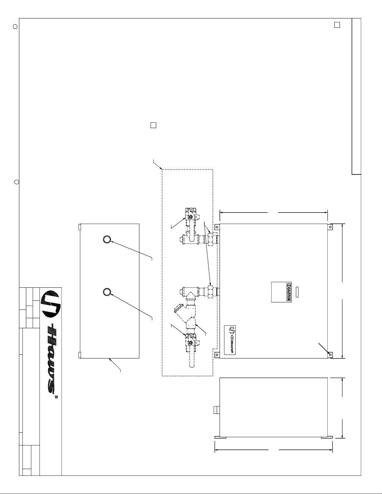
NOT SUPPLIED
MAKE SPECIFICATIONS AND MEASUREMENTS SUBJECT TO CHANGE WITHOUT NOTICE.
1 ITEMS SHOWN DASHED (IN BOX) ARE SHOWN FOR REFERENCE ONLY AND ARE
NOT SUPPLIED. MANUFACTURER REQUIRES "Y" STRAINER INSTALLATION FOR
UNIT DEBRIS PROTECTION AND WARRANTY COVERAGE. OTHER PARTS (UNIONS,
PLUGS, FULL-FLOW BALL VALVES, ETC., ARE RECOMMENDED TO PROVIDE
FUTURE SERVICEABILITY.
2. REFER TO EEMAX OWNER'S MANUAL FOR INSTALLATION INSTRUCTIONS.
THIS DOCUMENT IS TRUE AND CORRECT AT TIME OF PUBLICATION. CONTINUED PRODUCT IMPROVEMENTS
NOTES: (UNLESS OTHERWISE SPECIFIED)
R
1 1/4" NPT - HOT
WATER O UTLET
APPROVED:
DRAWN:
4886
VWC
REVISE D PER
ECN:
DATE:
1-30-14
DATE:
CHK'D.:
BY:ECN NO.
SCALE:
MODEL(S)
NA
INSTANTANEOUS HEATER
DRAWING TYPE: SIZE: A
1 1/4" NPT - COLD
WATER INLET
LOCKABLE BALL VALVE
LOCKABLE BALL VALVE
1 1/4" UNION
24.00
30.00
(MOUNTING HARDWARE
NOT SUPPLIED.)
4X ø.406 THRU
"Y" STRAINER
9326, 9327
INSTA LLATION
0002080089.D
DRAWING NO.
SHEET OF
16308A 0
11
REV
MODEL 9326 IS NEMA 4
MODEL 9327 IS NEMA 4X.
WATER HEATING UNIT
2X 13.47
(775) 359-4712 FAX (775) 359-7424
E-MAIL: HAWS@HAWSCO.COM
WEBSITE: WWW.HAWSCO.COM
SPARKS, NEVADA 89431
1455 KLEPPE LANE
PART NUMBER
26.25
Page 3
INSTALLATION INSTRUCTIONS
01/14
9326/9327
Page 3 of 12
AND
OWNER’S MANUAL
ELECTRIC INSTANTANEOUS WATER HEATERS WITH PhD
208 and 480 VAC three phase 32 – 126 kW
BEFORE ATTEMPTING ANY INSTALLATION OR SERVICE OF THIS
HEATER, MAKE SURE THE ELECTRICAL POWER IS DISCONNECTED.
FAILURE TO FOLLOW THESE INSTRUCTIONS CAN RESULT IN
SERIOUS INJURY, DEATH AND/OR PROPERTY DAMAGE.
Read and understand these instructions thoroughly before attempting the installation or service of this water
heater. This heater must be used to heat water only and be in a location where it is not subject to freezing
temperatures. If a water softener is used, the softener must be well-maintained and in good working order.
Any maintenance issues with a water softener could be detrimental to the operation or longevity of your
Eemax tankless water heater. The manufacturer is not liable for any damages resulting from improper
installation or misuse. The warranty of this water heater will depend upon the proper installation according
to these instructions.
This installation must conform to the latest requirements of the National Electrical Code and all applicable
state and local codes. This information is available through your local authorities. You must understand and
comply with these requirements before beginning this installation. Eemax recommends your heater be
installed by a licensed plumber and electrician. User instructions for the unit controls start on page 6.
This unit is not required by UL 499 to have a Temperature and Pressure relief valve (T&P). You should check
with local codes to find out if one is required in your area. If it is, it must be installed in the outlet hot water
pipe between the heater and the isolation valve.
This heater features a user friendly digital interface for ease of operation. Information is displayed through
a 16 character alpha numeric LCD and is controlled by 4 simple push buttons. The unit features silent
operation and internal diagnostics. The desired temperature can easily be set or altered as necessary. Once
the desired temperature is achieved, the control can be locked to avoid tampering.
EX07200-15 Rev. 1
1
Page 4
SAVE THESE INSTRUCTIONS
1) MOUNTING THE HEATER TO THE WALL
PAGE 3
2) PLUMBING HOOK-UP
PAGE 3
3) ELECTRICAL HOOK-UP
PAGE 4
4) COMMISSIONING THE HEATER
PAGE 5
5) CONTROL FEATURES
PAGE 6
6) REPAIR PARTS
PAGE 9
01/14
9326/9327
Page 4 of 12
TABLE OF CONTENTS
IMPORTANT SAFETY INSTRUCTIONS
The following instructions are provided pursuant to Canadian UL/Electrical Code requirements:
A green terminal (or a wire connector marked “G”, “GR, “Ground”, or “GROUNDING”) is provided within
the control box. To reduce the risk of electric shock, connect this terminal or connector to the grounding
terminal of the electric service or supply panel with a continuous copper wire in accordance with the
Canadian Electrical Code, Part I. (Canadian Installations Only)
Connect only to a circuit protected by a Class A ground fault circuit interrupter.
Attention: Brancher uniquement à un circuit protégé par un disjoncteur de fuite de
terre de Classe A. (Canadian Installations Only)
Do not install in a bath enclosure or shower stall or connect to a salt-regenerated water
softener or a water supply of salt water. Attention: Ne pas installer dans une baignoire
ou une cabine de douche et ne pas brancher à un adoucisseur d’eau régénéré avec du
sel ou à un approvisionnement en eau salée. (Canadian Installations Only)
Use copper conductors only. Use bonding conductor in accordance with the Canadian Electrical Code Part I.
Utilisez dez conducteurs en cuive uniquement. Utilisez des conducteurs de mize à la masse conformement
au Code Canadien de L’Électricité, Partie I. (Canadian Installations Only)
2
Page 5

1) MOUNTING THE HEATER TO THE WALL
01/14
9326/9327
Page 5 of 12
Please follow the mounting instructions as appropriate to your installation. Whenever possible, locate the
heater as close to the point of hot water use as possible. Time-to-temperature performance will improve
the closer the heater is installed to the point of use.
This heater must be installed in a location where
it is not subject to freezing temperatures.**
Make sure the brass fittings are at the bottom of the
heater and pointing “DOWN”. No other heater
orientation is permitted.
Install the heater with cabinet using the supplied
mounting feet following the instructions provided with
the cabinet. Be sure to use appropriately rated fasteners
to hold the cabinet/heater in place.
2) PLUMBING HOOK-UP
The heater is equipped with NPT brass fittings. Make
sure ONLY NPT fittings are used for connection to this
heater.
Make the cold water inlet connection to the lower RIGHT
fitting and the hot water outlet connection to the lower
LEFT fitting. Reversed connections will cause erratic
operation and premature heater failure.
HOT
WATER
OUT
NEVER USE PIPE DOPE WHEN MAKING PLUMBING CONNECTIONS TO THIS HEATER.
FOLLOW STANDARD INDUSTRY PRACTICE WITH CAREFUL APPLICATION OF TEFLON
TAPE. DO NOT ALLOW TEFLON TAPE TO GET INTO THE HEATER.
NEVER SOLDER ANY PIPE CONNECTIONS WHILE ATTACHED TO THIS HEATER - DAMAGE
TO THE HEATER WILL RESULT. DOING THIS WILL VOID THE WARRANTY.
** Does not apply to SafeAdvantage with
Freeze Protection option.
COLD
WATER
IN
3
Page 6

Eemax requires an inlet Y-strainer be installed for
01/14
9326/9327
Page 6 of 12
unit debris protection and warranty coverage.
Eemax also commends 2 unions, 2 full flow ball valves
and two drain plugs be installed for future
serviceability. These components are supplied by
others. (See photo to right.)
Run water through the cold water inlet pipe to purge
it of any debris before making final plumbing
connections to the heater.
Open both ball valves, check for leaks and repair as needed. Finally, open all hot water outlets – one at a time
– and purge the system from any air pockets. Allow water to run until water flow is continuous and then close
the hot water outlets
3) ELECTRICAL HOOK-UP
Installation and service is to be performed by a licensed
electrician or qualified serviceman.
BEFORE BEGINNING ANY WORK ON THIS INSTALLATION, BE SURE THAT THE
ELECTRICAL BREAKER IS “OFF” AND THAT ALL MOUNTING AND PLUMBING
WORK HAS BEEN COMPLETED PER THESE INSTRUCTIONS.
This heater must have its own independent circuit using insulated, UL listed wire conductors of the
appropriate size suitable for up to 75° C and protected by the correctly rated circuit breaker.
See chart on next page.
Before starting any electrical work VERIFY there is no
power at the heater before proceeding !
L1 L2 L3 gnd
The power conductors are to be secured to the L1, L2
and L3 connectors on the terminal block. The ground
is to be secured to the GND connector to the right of
the terminal block.
FAILURE TO GROUND THE SYSTEM MAY RESULT IN SERIOUS INJURY,
DEATH AND/OR PROPERTY DAMAGE.
4
Page 7

4) COMMISSIONING THE HEATER
ELECTRICAL SPECIFICATIONS
VOLTS
AMPS
RECOMMENDED
MODEL
3-PHASE DELTA
Kw
PER PHASE
WIRE SIZE (CU) 75° C
AP032208
208
32
89
3 AWG
AP041208
208
41
114
2 AWG
AP054208
208
54
150
1/0
AP064208
208
64
178
3/0
AP036480
480
36
44
8 AWG
AP048480
480
48
58
6 AWG
AP054480
480
54
65
6 AWG
AP072480
480
72
86
3 AWG
AP108480
480
108
130
1 AWG
AP126480
480
126
152
2/0
01/14
9326/9327
Page 7 of 12
BEFORE SWITCHING THE ELECTRICAL BREAKER “ON”, MAKE SURE
THE INLET AND OUTLET BALL VALVES ARE FULLY OPEN AND WATER
IS FLOWING THROUGH ALL POINTS OF USE FOR A MINUTE OR TWO
UNTIL THE FLOW IS CONTINUOUS AND FREE FROM AIR POCKETS.
DO NOT SWITCH THE BREAKER “ON” IF THERE IS ANY POSSIBILITY
THE WATER IN THE HEATER IS FROZEN.
After verifying the heater has been
purged of air (see above) turn the circuit
breaker/disconnect “ON” and observe
the start-up sequence on the display.
The LCD screen will display the SETPOINT
TEMPERATURE in degrees F.
Below the display are 4 push buttons that
are used to control the function of the
heater. Press the UP or DOWN buttons to
establish your desired temperature. Refer
to the CONTROL FEATURES section of this
manual for additional information.
The heater is fully installed and ready for use.
5
Page 8

TEMPERATURE RISE AT SPECIFIED FLOW RATE, DEGREES F:
TURN-ON
3.0
4.0
6.0
8.0
12.0
20.0
25.0
30.0
MODEL
GPM
GPM
GPM
GPM
GPM
GPM
GPM
GPM
GPM
AP032208
1.5
7355362718
---
AP041208
1.5
9370473523
---
AP054208
1.5
*
9261463118
-
-
AP064208
1.5
*
*
7355362217
-
AP036480
1.5
8261413120
12
-
-
AP048480
1.5
*
8255412716
-
-
AP054480
1.5
*
92
614631
18
-
-
AP072480
2.5
*
*
8261412520
-
AP108480
2.5
***
926137
30
-
AP126480
2.5
***
*
724334
29
* Temperature limited to preset value
1) The SETPOINT TEMP or ACTUAL TEMP screen can be
selected for display as the home screen. Either of these
screens will remain on the display when the backlight timer
expires.
2) There is a 5 minute time delay built into the control.
Regardless of which screen is being displayed, after 5
minutes of inactivity, the display will revert to the SETPOINT
TEMP screen.
3) The 4 push buttons are used to control the operation of
the heater. The LEFT and RIGHT buttons shift the display
from one screen to another. The DOWN and UP buttons
may change the values within selected screens.
4) As an example, when the screen displays SETPOINT
TEMP, the desired hot water temperature will increase 1
degree for each press of the UP button and decrease 1
degree for each press of the DOWN button. Note that
minimum and maximum setpoint temperatures are
established at the factory.
01/14
9326/9327
Page 8 of 12
5) CONTROL FEATURES
BEFORE USING THIS CONTROL, MAKE SURE ALL PRIOR INSTALLATION STEPS HAVE
BEEN PROPERLY COMPLETED, ELECTRICAL POWER IS ON AND WATER IS PRESENT
IN THE HEATER.
PUSH BUTTON FLOW CHART
OR
6
Page 9

5) The LEFT and RIGHT buttons shift the display from one
screen to another. From the INLET TEMP screen, one
press of the RIGHT button will shift the display to the
SETPOINT TEMP screen. INLET TEMP shows the actual
temperature of the water entering the heater.
6) From the SETPOINT TEMP screen, one press of the
RIGHT button will shift the display to the ACTUAL TEMP
screen. This shows the actual temperature of the water
leaving the heater.
7) From the ACTUAL TEMP screen, one press of the RIGHT
button will shift the display to the LOAD PCT screen. This
shows the electrical power consumption as a percentage
of full power.
8) From the LOAD PCT screen, one press of the RIGHT
button will shift the display to the FLOWRATE screen. This
shows the rate of flow of water through the heater.
9) From the FLOWRATE screen, one press of the RIGHT
button will shift the display to the UNITS screen. This
shows the units of measure in either the ENGLISH or
METRIC systems. ENGLISH units are degrees Fahrenheit
and gallons per minute. METRIC units are degrees Celsius
and liters per second. Use the UP and Down buttons to
select the desired units of measure.
10) From the UNITS screen, one press of the RIGHT button
will shift the display to the SOFTWARE REVISION screen.
This shows the revision level of the software in the
control.
11) From the SOFTWARE REVISION screen, one press of
the RIGHT button will shift the display to the ERRORS
screen. This shows the error history of the heater.
“0 ERRORS” means that no errors have occurred.
If the heater has an error history of 4 errors; this history
will be displayed on the screen as shown. “CODE 1:E0”
refers to the first error and indicates it to be an E0 error.
One press of the UP button will show the second error as
“CODE 2:E0” and having the same E0 error.
Continued pressing of the UP or Down buttons will scroll
through each of the errors in the history (in this case a
total of 4). ERRORS indicate an undesirable condition but
will not shut down the operation of the heater.
01/14
9326/9327
Page 9 of 12
7
Page 10

12) FAULTS are communicated through the LCD display.
The display will switch from the SETPOINT screen to the
FAULT screen and back again every 3 seconds. FAULTS
indicate an undesirable condition and will immediately
shut down the operation of the heater. If faults are
appearing on your heater call Eemax Technical Support
for assistance.
ERROR CODES:
13) The security of the heater settings is provided by
pressing and holding the LEFT and UP buttons for 3
seconds to lock the buttons. Once locked, the buttons
have no function. Press and hold the same LEFT and UP
buttons for 3 seconds to unlock the buttons.
The security status can be checked at any time by
pressing any one button. If the system is locked, the
screen will display “BUTTONS LOCKED”.
[ + ] =
01/14
9326/9327
Page 10 of 12
E0: Excessive water flow detected
Corrective action: Using the OUTLET BALL VALVE, slowly reduce water flow until
the desired temperature is achieved. The temperature is proportional to the flow through the
heater; the lower the flow, the higher the temperature and vice versa.
Keep the INLET BALL VALVE fully “OPEN”. NEVER RESTRICT THE WATER
FLOW USING THE INLET VALVE.
E1: Inlet temperature too hot to generate heat
FAULT CODES:
F0: Thermistor out of range
F1: No change in water temperature detected
F2: Leak detected
8
Page 11

6) REPAIR PARTS
13) The display can be turned off or on. Press and hold
the DOWN and RIGHT buttons for 3 seconds. If the
display is off, it can be turned on by pressing and
holding the same DOWN and RIGHT buttons for 3
seconds.
+[+ + ]=
01/14
9326/9327
Page 11 of 12
Service and repairs are to be performed by licensed
electricians or qualified servicemen.
BEFORE ATTEMPTING ANY REPAIRS TO THE HEATER, MAKE SURE THAT THE
ELECTRICAL BREAKER IS “OFF” AND CONFIRM THAT THERE IS NO VOLTAGE AT
THE HEATER.
Contactor
Emergency
Cut Off
Optical
Sensor
Board
Heating
Element
Assembly *
Transformer
Control
Board
Fuse
Hall Effect Board
(behind Flow Meter)
Flow Meter Kit **
Triac
* Heating element assembly consists of one heater core and wire element(s) complete.
** Flow meter kit consists of paddle wheel, dowel pin, O ring and 4 mounting screws.
9
Page 12

REPAIR PARTS
Control
Flow Meter
Hall Effect
Model
Transformer
Board
Fuse
Kit
Board
AP032208
EX08303-07
EX08300-00
EX198
EX78000-00
EX08601-00
AP041208
EX08303-07
EX08300-00
EX08200-11
EX78000-00
EX08601-00
AP054208
EX08303-07
EX08300-00
EX198
EX78000-00
EX08601-00
AP064208
EX08303-07
EX08300-00
EX08200-11
EX78000-01
EX08601-00
AP036480
EX08303-05
EX08300-00
N/A
EX78000-00
EX08601-00
AP048480
EX08303-05
EX08300-00
N/A
EX78000-00
EX08601-00
AP054480
EX08303-08
EX08300-00
EX08200-07
EX78000-00
EX08601-00
AP072480
EX08303-08
EX08300-00
EX198
EX78000-01
EX08601-00
AP108480
EX08303-08
EX08300-00
EX198
EX78000-01
EX08601-00
AP126480
EX08303-08
EX08300-00
EX08200-11
EX78000-01
EX08601-00
Heating
Optical
Element
Sensor
Emergency
Model
Triac
Assembly
Board
Cut Off **
Contactor
AP032208
EX78002-00
EX77000-08.2
EX78001-00
EX278A-KIT
EX08306-02
AP041208
EX78002-00
EX77000-06.4
EX78001-00
EX278A-KIT
EX08306-00
AP054208
EX78002-00
EX77000-04.8
EX78001-00
EX278A-KIT
EX08306-02
AP064208
EX78002-00
EX77000-04.1
EX78001-00
EX278A-KIT
EX08306-02
AP036480
EX78002-00
EX77000-09.6
EX78001-00
EX278A-KIT
EX08306-02
AP048480
EX78002-00
EX77000-14.4
EX78001-00
EX278A-KIT
EX08306-00
AP054480
EX78002-00
EX77000-06.4
EX78001-00
EX278A-KIT
EX08309-00
AP072480
EX78002-00
EX77000-09.6
EX78001-00
EX278A-KIT
EX08309-00
AP108480
EX78002-00
EX77000-06.4
EX78001-00
EX278A-KIT
EX08309-00
AP126480
EX78002-00
EX77000-05.5
EX78001-00
EX278A-KIT
EX08309-00
01/14
9326/9327
Page 12 of 12
** Use EX278-A for all models EXCEPT:
- ‘S’ and ‘DB’ options use EX278D-KIT
-‘EE’ and ‘EFD’ options use EX278E-KIT
If you need any assistance from our Technical Service Department,
make sure you can identify this water heater by having the model no: ____________________
and serial number: _____________________. Call 203-267-7890 or toll free: 800-543-6163.
Email: info@eemaxinc.com Web: www.Eemax.com
Eemax Inc., 400 Captain Neville Drive, Waterbury, CT 06705
10
 Loading...