

Page 1
INSTALLATION INSTRUCTIONS
AND OWNER’S MANUAL
FOR
ELECTRIC ON-DEMAND TANKLESS WATER HEATERS:
SpecAdvantage with PhD Technology
SafeAdvantage with PhD Technology
208 and 480 VAC three phase 32 – 144 kW
600 VAC three phase 130 / 150 kW
BEFORE ATTEMPTING INSTALLATION OR SERVICE OF THIS
HEATER, DISCONNECT ELECTRICAL POWER AT THE SERVICE BREAKER
PANEL. FAILURE TO DO SO CAN RESULT IN SERIOUS INJURY, DEATH
AND/OR PROPERTY DAMAGE.
1
IMPORTANT SAFETY INSTRUCTIONS
A green terminal (or a wire connector marked “G”, “GR, “Ground”, or “GROUNDING”) is provided within the
control box. To reduce the risk of electric shock, connect this terminal or connector to the grounding terminal of
the electric service or supply panel with a continuous copper wire in accordance with your local electrical code.
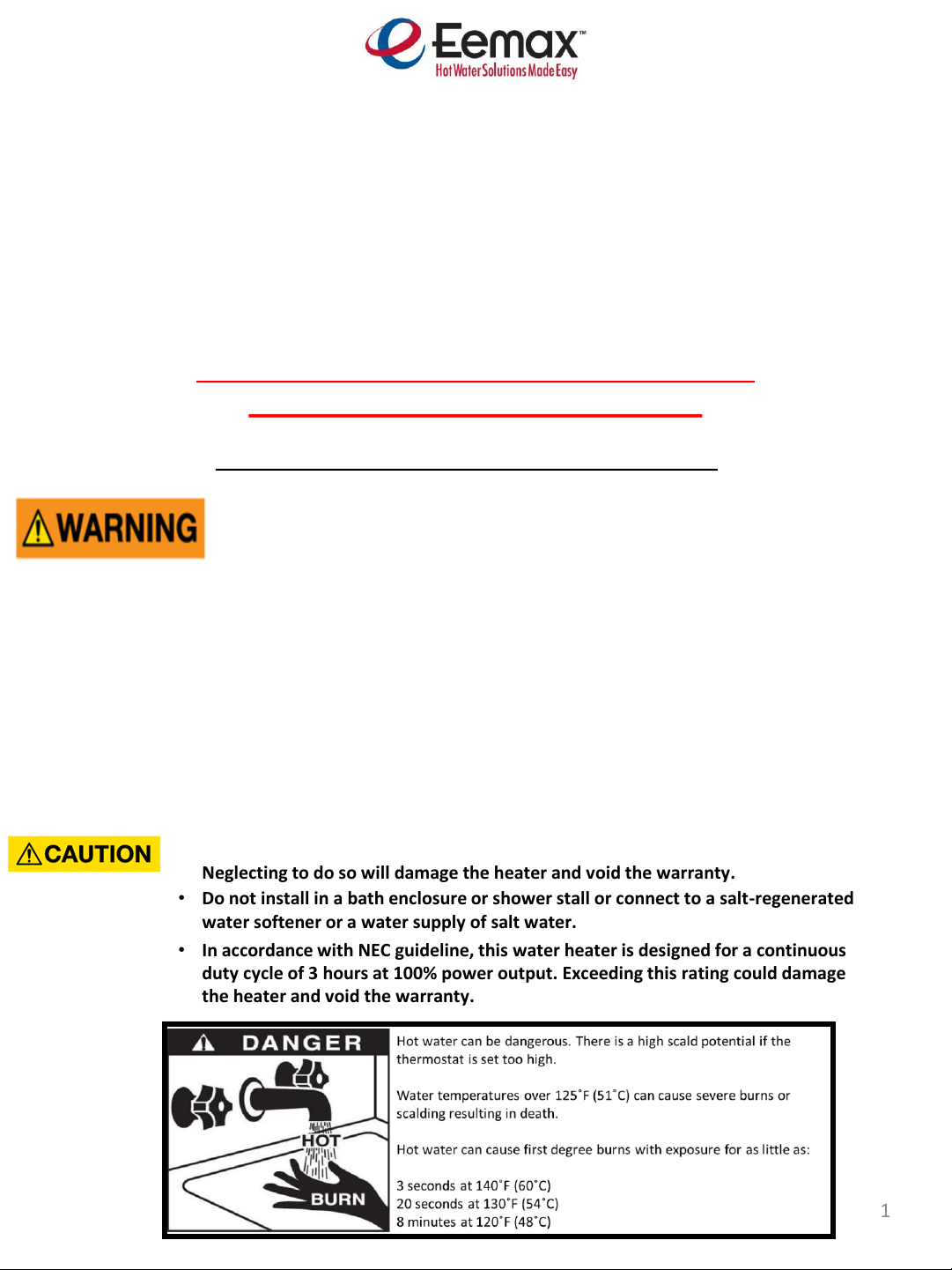
• Do not install in a bath enclosure or shower stall or connect to a salt-regenerated
water softener or a water supply of salt water.
• Use copper conductors only.
• Use Water Hammer Arrestors in applications with excess pipe lengths or fast acting
valves, neglecting to do so will damage the heater and void the warranty.
• Use appropriate water conditioning to prevent water hardness in excess of 10 grains
per gallon. Also ensure that the pH level of the water is between 6.5 – 7.5.
Neglecting to do so will damage the heater and void the warranty.
• In accordance with NEC guideline, this water heater is designed for a continuous
duty cycle of 3 hours at 100% power output. Exceeding this rating could damage
the heater and void the warranty.
• Provide your heater with potable, uninterrupted supply of water at a constant
minimum pressure of 25 or 45 PSI (based on model) and maximum pressure of 150 PSI.
Page 2

2
This page intentionally left blank
Page 3

TABLE OF CONTENTS
1) MOUNTING THE HEATER TO THE WALL …………………………………………………………
PAGE 4
2) PLUMBING HOOK-UP ……………………………………………………………………………………
PAGE 5
3) ELECTRICAL HOOK-UP …………………………………………………………………………………..
PAGE 7
4) COMMISSIONING THE HEATER ……………………………………………………………………..
PAGE 8
5) CONTROL FEATURES …………………………………………………………………………………….
PAGE 9
6) REPAIR
PARTS …………………………………………………………………………………………….
7) OPTIONS …...……………………………………………………………………………………………...
PAGE 12
PAGE
14
Read and understand these instructions thoroughly before attempting the installation or service of this water
heater. This heater must be used to heat water only and be in a location where it is not subject to freezing
temperatures unless supplied with factory installed freeze protection. If a water softener is used, the
softener must be well-maintained and in good working order. Any maintenance issues with a water softener
could be detrimental to the operation or longevity of your Eemax tankless water heater. The manufacturer
is not liable for any damages resulting from improper installation or misuse. The warranty of this water
heater is contingent on proper installation according to these instructions. Please refer to the warranty card
packaged with this heater.
Installation of this water heater must conform to the latest requirements of the National Electrical Code and
all applicable state and local codes. Detailed information on state and local codes is available through your
local authorities. You must understand and comply with these requirements before beginning the
installation. Eemax recommends your heater be installed by a licensed plumber and electrician.
Per UL 499, this water heater is not required to be installed with a Temperature and Pressure relief valve
(T&P). However, local codes may vary. In case a T&P relief valve is required, it must be installed on the
outlet hot water line heater between the heater and the isolation valve.
3
Page 4
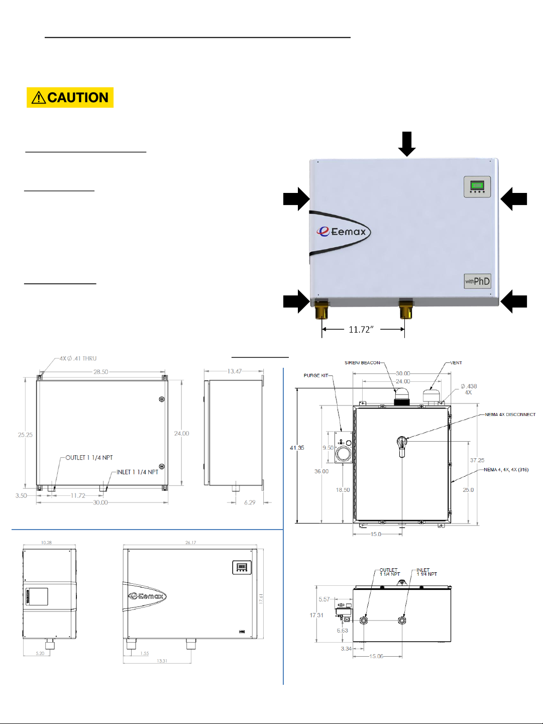
1) MOUNTING THE HEATER TO THE WALL
Please follow the mounting instructions as appropriate to your installation. Eemax recommends the heater
be installed close to the point of use.
Make sure the brass fittings are at the bottom of the
heater. No other heater orientation is permitted.
Recommended clearances:
Leave a service clearance of at least 12” inches on all
sides of the heater.
SafeAdvantage: SafeAdvantage water heaters are
enclosed in a Nema 4 cabinet. For wall mount
installation, use appropriately rated fasteners to secure
the cabinet with the provided mounting tabs on the
outside of each corner to secure it to the wall. For floor
mount installation, enclosure legs are available for
purchase.
SpecAdvantage: Remove the cover by removing the
cover screws as indicated by the arrows (right) and
fasten the heater to the wall using the mounting holes
located at each corner of the back plate. Be sure to use
appropriately rated fasteners to secure the heater in
place.
4
This heater must be installed in a location where it is not subject to freezing
temperatures, unless supplied with factory installed freeze protection
SafeAdvantage
Spec Advantage
Larger cabinet for all optional features
(GFCI, Freeze Protection, Electrical Disconnect,
Class 1 Div 2, Siren/ Beacon)
Dimensions
Page 5
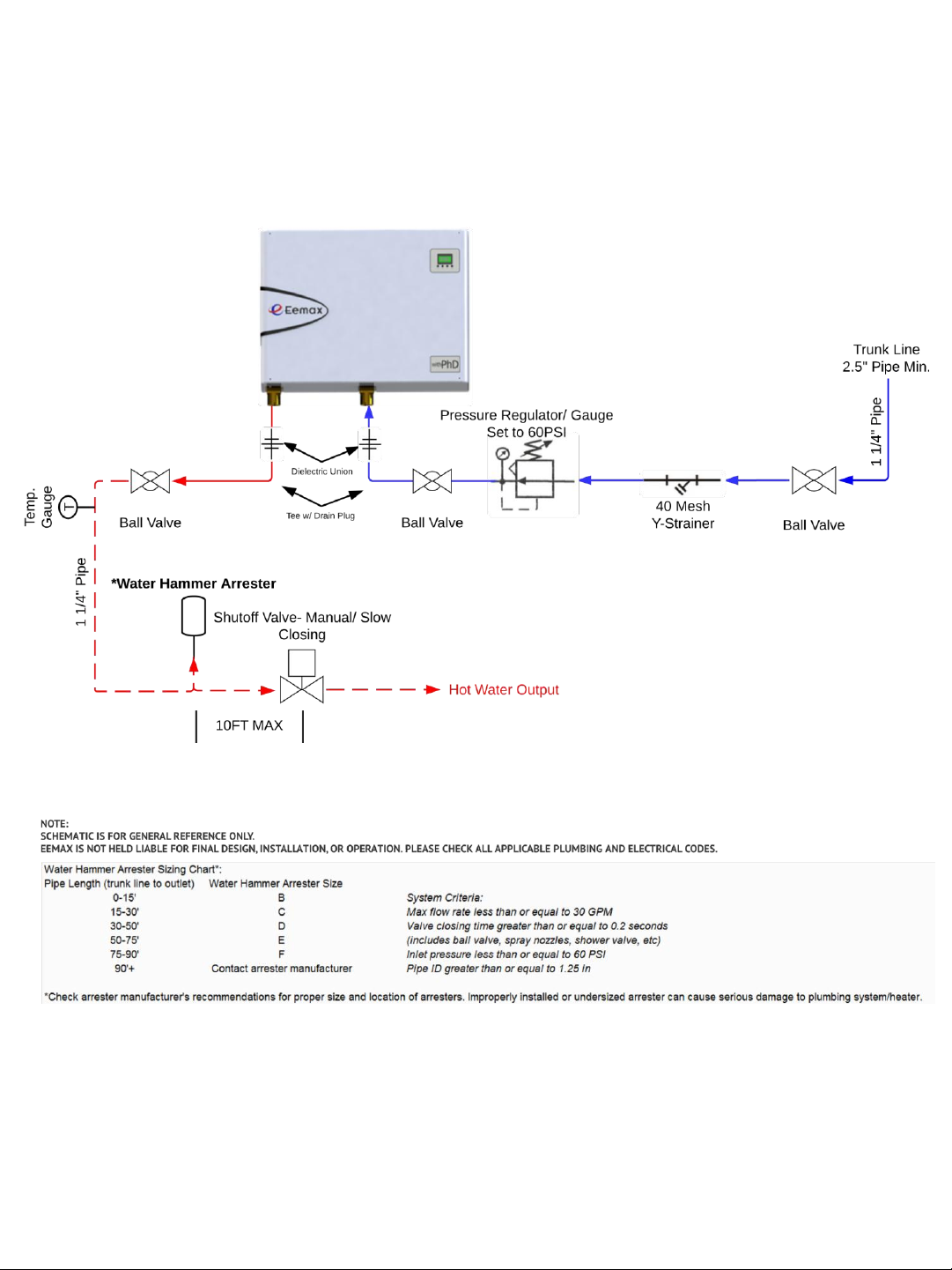
2) PLUMBING HOOK-UP
Page 6
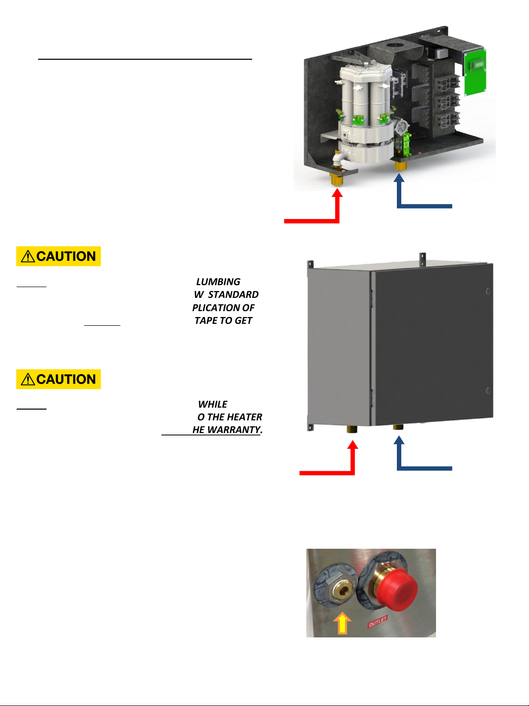
NEVER USE PIPE DOPE WHEN MAKING PLUMBING
CONNECTIONS TO THIS HEATER. FOLLOW STANDARD
INDUSTRY PRACTICE WITH CAREFUL APPLICATION OF
TEFLON TAPE. DO NOT ALLOW TEFLON TAPE TO GET
INTO THE HEATER.
NEVER SOLDER ANY PIPE CONNECTIONS WHILE
ATTACHED TO THIS HEATER - DAMAGE TO THE HEATER
WILL RESULT. DOING THIS WILL VOID THE WARRANTY.
6
2) PLUMBING HOOK-UP (continued)
The heater is equipped with NPT brass fittings. Make
sure ONLY NPT fittings are used for connection to this
heater.
Connect the cold water line with the inlet connection
(RIGHT fitting)
Connect the outlet pipe with the outlet fitting (LEFT
fitting).
Do not reverse connections.
COLD
WATER
IN
HOT
WATER
OUT
COLD
WATER
IN
HOT
WATER
OUT
A PRV Vent is located fitting. The PRV Vent is not a code
compliant pressure relief valve. Check local codes to see if a
code compliant T&P Relief Valve is required in your
installation.
Page 7
3) ELECTRICAL HOOK-UP
BEFORE BEGINNING ANY WORK ON THIS INSTALLATION, BE SURE THAT THE
ELECTRICAL BREAKER IS “OFF” AND THAT ALL MOUNTING AND PLUMBING
WORK HAS BEEN COMPLETED PER THESE INSTRUCTIONS.
This heater must have its own independent circuit using insulated, UL listed wire conductors of the
appropriate size suitable for up to 90° C and protected by the correctly rated circuit breaker.
See chart on next page.
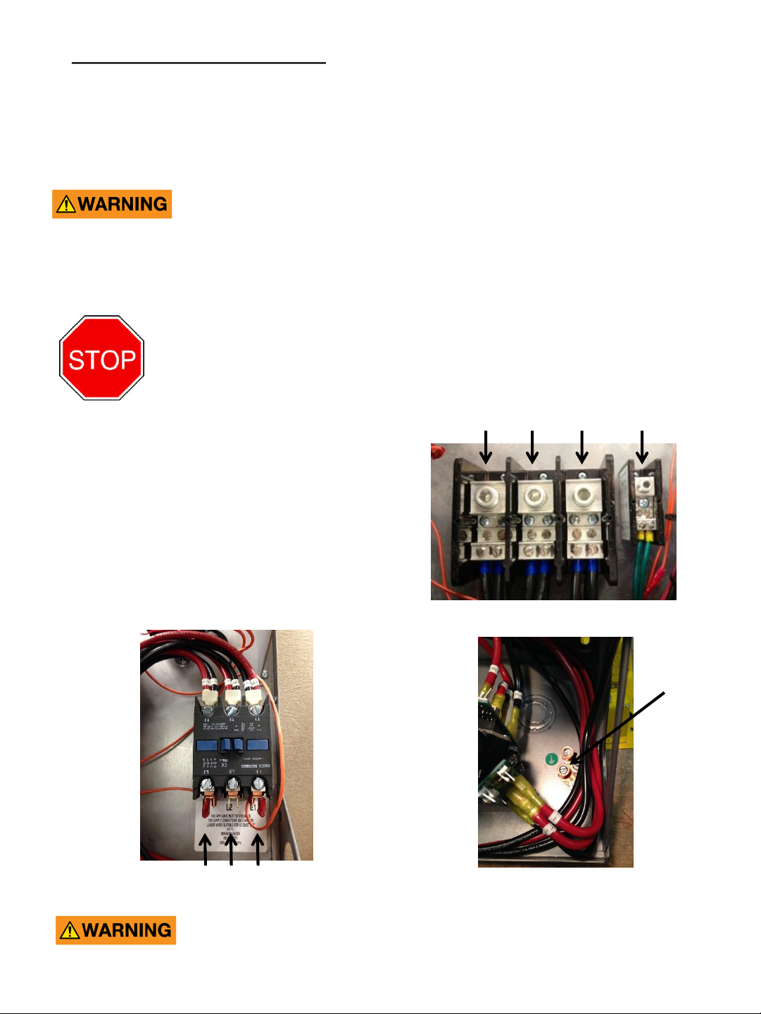
Before starting any electrical work VERIFY there is no
power at the heater before proceeding !
The power conductors are to be secured
to the L1, L2 and L3 connectors on the
terminal block (Fig. 1) or contactor (Fig. 2).
The ground is to be secured to the GND
connector to the right of the terminal
block or below contactor (Fig 3).
Replace the cover. (SpecAdvantage only).
FAILURE TO GROUND THE SYSTEM MAY RESULT IN SERIOUS INJURY,
DEATH AND/OR PROPERTY DAMAGE.
L1 L2 L3 GND
7
Eemax recommends your heater be installed or serviced by a licensed plumber
and electrician.
Fig. 1
Fig. 3
Fig. 2
GND
L3 L2 L1
Page 8
4) COMMISSIONING THE HEATER
BEFORE SWITCHING THE ELECTRICAL BREAKER “ON”, MAKE SURE
THE INLET AND OUTLET BALL VALVES ARE FULLY OPEN AND WATER
IS FLOWING THROUGH ALL POINTS OF USE FOR A MINUTE OR TWO
UNTIL THE FLOW IS CONTINUOUS AND FREE FROM AIR POCKETS.
DO NOT SWITCH THE BREAKER “ON” IF THERE IS ANY POSSIBILITY
THE WATER IN THE HEATER IS FROZEN.
After verifying the heater has been
purged of air (see above) turn the circuit
breaker/disconnect “ON” and observe
the start-up sequence on the display.
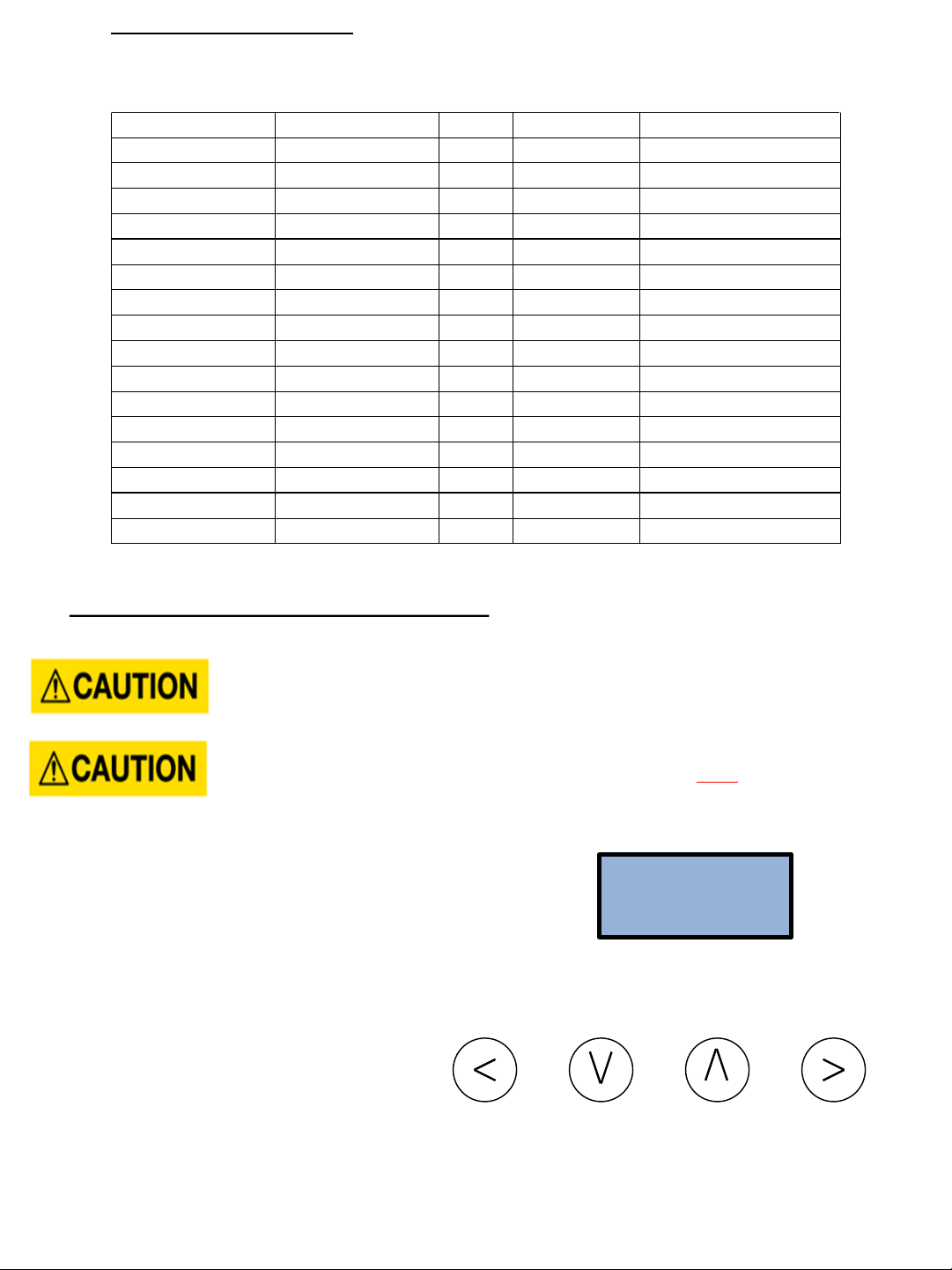
The LCD screen will display the SETPOINT
TEMPERATURE in degrees F.
Below the display are 4 push buttons that
are used to control the function of the
heater. Press the UP or DOWN buttons to
establish your desired temperature. Refer
to the CONTROL FEATURES section of this
manual for additional information.
The heater is fully installed and ready for use.
ELECTRICAL SPECIFICATIONS
VOLTS AMPS RECOMMENDED
MODEL 3-PHASE DELTA Kw PER PHASE WIRE SIZE (CU) 90° C
AP032208 208 32 89 1 AWG
AP036208 208 36 100 1 AWG
AP041208 208 41 114 1 AWG
AP054208 208 54 150 2/0
AP064208 208 64 178 3/0
AP036480 480 36 44 8 AWG
AP039480 480 39 47 8 AWG
AP048480 480 48 58 6 AWG
AP054480 480 54 65 4 AWG
AP063480 480 63 76 3 AWG
AP072480 480 72 86 3 AWG
AP096480 480 96 116 1 AWG
AP108480 480 108 130 1/0
AP126480 480 126 152 2/0
AP144480 480 144 173 3/0
AP130600 600 130 130 1 AWG
AP150600 600 150 144 1/0
8
SETPOINT
TEMP120F
Page 9

TEMPERATURE RISE AT SPECIFIED FLOW RATE, DEGREES F:
TURN-ON 3.0 4.0 6.0 8.0 12.0 20.0 25.0 30.0
MODEL GPM GPM GPM GPM GPM GPM GPM GPM GPM
AP032208 1.0 73 55 36 27 18 10 8 7
AP036208 1.0 82 61 41 29 20 12 9 8
AP041208 1.0 93 70 47 35 23 13 11 9
AP054208 1.5 123 92 61 46 31 18 14 12
AP064208 2.5 146 109 73 55 36 22 17 15
AP036480 1.0 82 61 41 31 20 12 9 8
AP039480 1.0 89 67 44 33 22 13 11 7
AP048480 1.0 109 82 55 41 27 16 13 11
AP054480 1.5 123 92 61 46 31 18 14 12
AP063480 2.5 143 108 72 53 36 22 17 14
AP072480 2.5 147 123 82 61 41 25 20 16
AP096480 2.5 * * 109 82 54 33 26 22
AP108480 2.5 * * 99 92 61 37 30 25
AP126480 2.5 * * 143 107 72 43 34 29
AP144480 2.5 * * * 122 82 49 40 34
AP130600 2.5 * * * 111 73 44 35 30
AP150600 2.5 * * * 128 85 52 40 35
5) CONTROL FEATURES
BEFORE USING THIS CONTROL, MAKE SURE ALL PRIOR INSTALLATION STEPS HAVE
BEEN PROPERLY COMPLETED, ELECTRICAL POWER IS ON AND WATER IS PRESENT
IN THE HEATER.
PUSH BUTTON FLOW CHART
1) The SETPOINT
TEMP or ACTUAL TEMP screen can be
selected for display
as the home screen. Either of these
screens will remain on the display when the backlight timer
expires.
2
) There is a 5 minute time delay built into the control.
Regardless of which screen is being displayed, after 5
minutes of inactivity, the display will revert to the SETPOINT
TEMP
screen.
3
) The 4 push buttons are used to control the operation of
the heater. The LEFT and RIGHT buttons shift the display
from one screen to another. The DOWN and UP buttons
may change the values within selected screens.
4) As an example, when the screen displays SETPOINT
TEMP, the desired hot water temperature will increase 1
degree for each press of the UP button and decrease 1
degree for each press of the DOWN button. Note that
minimum and maximum
setpoint temperatures are
established at the factory.
9
OR
ACTUAL
TEMP 75F
SETPOINT
TEMP120F
SETPOINT
TEMP120F
SETPOINT
TEMP120F
Page 10

5) The LEFT and RIGHT buttons shift the display from one
screen to another. From the INLET TEMP screen, one
press of the RIGHT button will shift the display to the
SETPOINT TEMP screen. INLET TEMP shows the actual
temperature of the water entering the heater.
6) From the SETPOINT TEMP screen, one press of the
RIGHT button will shift the display to the ACTUAL TEMP
screen. This shows the actual temperature of the water
leaving the heater.
7)
From the ACTUAL TEMP
screen, one press of the RIGHT
button will shift the display to the LOAD
PCT screen. This
shows the electrical power consumption as a percentage
of full power.
8)
From the LOAD PCT screen, one press of the RIGHT
button will shift the display to the FLOWRATE screen. This
shows the rate of flow of water through the heater.
9)
From the FLOWRATE screen, one press of the RIGHT
button will shift the display to the UNITS screen. This
shows the units of measure in either the ENGLISH or
METRIC systems. ENGLISH units are degrees Fahrenheit
and gallons per minute. METRIC units are degrees Celsius
and liters per second. Use the UP and Down buttons to
select the desired units of measure.
10) From the UNITS screen, one press of the RIGHT button
will shift the display to the SOFTWARE REVISION screen.
This shows the revision level of the software in the
control.
11)
From the SOFTWARE REVISION screen, one press of
the RIGHT button will shift the display to the ERRORS
screen. This shows the error history of the heater.
“0 ERRORS” means that no errors have occurred
.
If the heater has an error history of 4 errors; this history
will be displayed on the screen as shown. “CODE 1:E0”
refers to the first error and indicates it to be an E0 error.
One press of the UP button will show the second error as
“CODE 2:E0” and having the same E0 error.
Continued pressing of the UP or Down buttons will scroll
through each of the errors in the history (in this case a
total of 4). ERRORS indicate an undesirable condition but
will not shut down the operation of the heater.
10
SETPOINT
TEMP120F
INLET
TEMP 74F
SETPOINT
TEMP120F
ACTUAL
TEMP 75F
ACTUAL
TEMP 75F
LOAD PCT
0% PWR
LOAD PCT
0% PWR
FLOWRATE
??.? GPM
FLOWRATE
??.? GPM
UNITS
ENGLISH
UNITS
ENGLISH
SOFTWARE
20131218
SOFTWARE
20131218
1 ERROR
CODE1:F0
Page 11

12)
FAULTS are communicated through the LCD display.
The display will switch from the SETPOINT screen to the
FAULT screen and back again every 3 seconds. FAULTS
indicate an undesirable condition and will immediately
shut down the operation of the heater. If faults are
appearing on your heater call Eemax Technical Support
for assistance.
ERROR CODES:
E0: Excessive water flow detected
Corrective action: Using the OUTLET BALL VALVE, slowly reduce water flow until
the desired temperature is achieved. The temperature is proportional to the flow through the
heater; the lower the flow, the higher the temperature and vice versa.
Keep the INLET BALL VALVE fully “OPEN”. NEVER RESTRICT THE WATER
FLOW USING THE INLET VALVE.
E1: Inlet temperature too hot to generate heat
FAULT CODES:
F0: Outlet thermistor out of range
F1: No change in water temperature detected
F2: Dry fire detected - Optical Sensor Tripped
F3: Excessive dry fire occurrences detected
F4: Inlet thermistor out of range
13)
The security of the heater settings is provided by
pressing and holding the LEFT and UP buttons for 3
seconds to lock the buttons. Once locked, the buttons
have no function. Press and hold the same LEFT and UP
buttons for 3 seconds to unlock the buttons
.
The security status can be checked at any time by
pressing any one button. If the system is locked, the
screen will display “BUTTONS LOCKED”.
[ + ] =
11
FAULT
CODE: F0
BUTTONS
LOCKED
SETPOINT
TEMP120F
Page 12

6) REPAIR PARTS
BEFORE ATTEMPTING ANY REPAIRS TO THE HEATER, MAKE SURE THAT THE
ELECTRICAL BREAKER IS “OFF” AND CONFIRM THAT THERE IS NO VOLTAGE AT
THE HEATER.
* Heating element assembly consists of one heater core and wire element(s) complete.
** Flow meter kit consists of paddle wheel, dowel pin, O ring and 4 mounting screws.
Transformer
Control
Board
Fuse
Flow Meter Kit **
Hall Effect Board
(behind Flow Meter)
Triac/SSR (not shown)
Heating
Element
Assembly *
Optical
Sensor
Board
Emergency
Cut Off
Contactor
12
14) The display can be turned off or on. Press and hold
the DOWN and RIGHT buttons for 3 seconds. If the
display is off, it can be turned on by pressing and
holding the same DOWN and RIGHT buttons for 3
seconds.
+[+ + ]
=
Service and repairs are to be performed by licensed
electricians or qualified servicemen.
ACTUAL
TEMP 75F
Page 13

REPAIR PARTS (continued)
Control
Flow Meter
Hall Effect
Model
Transformer
Board Fuse Kit Board
AP032208
EX08303
-07
EX08300
-00 EX198
EX78000
-00
EX08601
-00
AP036208
EX08303
-07
EX08300
-00
EX08200
-11
EX78000
-00
EX08601
-00
AP041208
EX08303
-07
EX08300
-00
EX08200
-11
EX78000
-00
EX08601
-00
AP054208
EX08303
-07
EX08300
-00 EX198
EX78000
-00
EX08601
-00
AP064208
EX08303
-07
EX08300
-00
EX08200
-11
EX78000
-01
EX08601
-00
AP036480
EX08303
-05
EX08300
-00 N/A
EX78000
-00
EX08601
-00
AP039480
EX08303
-05
EX08300
-00 N/A
EX78000
-00
EX08601
-00
AP048480
EX08303
-05
EX08300
-00 N/A
EX78000
-00
EX08601
-00
AP054480
EX08303
-08
EX08300
-00
EX08100
-07
EX78000
-00
EX08601
-00
AP063480
EX08303
-08
EX08300
-00 EX198
EX78000
-01
EX08601
-00
AP072480
EX08303
-08
EX08300
-00 EX198
EX78000
-01
EX08601
-00
AP096480
EX08303
-08
EX08300
-00 EX198
EX78000
-01
EX08601
-00
AP108480
EX08303
-08
EX08300
-00 EX198
EX78000
-01
EX08601
-00
AP126480
EX08303
-08
EX08300
-00
EX08200
-11
EX78000
-01
EX08601
-00
AP144480
EX08303
-08
EX08300
-00
EX08200
-13
EX78000
-01
EX08601
-00
AP130600
EX08303
-06
EX08300
-00
EX08200
-13
EX78000
-01
EX08601
-00
AP150600
EX08303
-06
EX08300
-00
EX08200
-13
EX78000
-01
EX08601
-00
Heating Optical
Element Sensor
Emergency
Model
Triac/SSR*
Assembly Board
Cut Off **
Contactor
AP032208
EX78002
-00
EX77000-8.12
EX78001-00
EX278A-KIT
EX08306
-02
AP036208
EX78002
-00
EX77000-7.20
EX78001-00
EX278A-KIT
EX08306
-00
AP041208
EX78002
-00
EX77000-6.33
EX78001-00
EX278A-KIT
EX08306
-00
AP054208
EX78002
-00
EX77000-4.81
EX78001-00
EX278A-KIT
EX08309
-00
AP064208
EX78002
-00
EX77000-4.06
EX78001-00
EX278A-KIT
EX08309
-00
AP036480
EX78002
-00
EX77000-19.2
EX78001-00
EX278A-KIT
EX08306
-02
AP039480
EX78002
-00
EX77000-17.7
EX78001-00
EX278A-KIT
EX08306
-00
AP048480
EX78002
-00
EX77000-14.4
EX78001-00
EX278A-KIT
EX08306
-00
AP054480
EX78002
-00
EX77000-12.8
EX78001-00
EX278A-KIT
EX08306
-02
AP063480
EX78002
-00
EX77000-18.2
EX78001-00
EX278A-KIT
EX08306
-02
AP072480
EX78002
-00
EX77000-19.2
EX78001-00
EX278A-KIT
EX08306
-02
AP096480
EX78002
-00
EX77000-14.4
EX78001-00
EX278A-KIT
EX08309
-00
AP108480
EX78002
-00
EX77000-12.8
EX78001-00
EX278A-KIT
EX08309
-00
AP126480
EX78002
-00
EX77000-10.97
EX78001-00
EX278A-KIT
EX08309
-00
AP144480
EX08200
-12 EX77000-9.6
EX78001-00
EX278A-KIT
EX08309
-00
AP130600
EX08200
-12
EX77000-16.6
EX78001-00
EX278A-KIT
EX08309
-00
AP150600
EX08200
-12
EX77000-14.4
EX78001-00
EX278A-KIT
EX08309
-00
* For “S” models use SSR EX08200-12
** Use EX278-A for all models EXCEPT:
- ‘S’ and ‘DB’ options use EX278D-KIT
-‘EE’ and ‘EFD’ options use EX278E-KIT
13
Page 14

Optional Class 1 Division 2
14
7) OPTIONS
Page 15

151617
Page 16

Page 17

Page 18

18
NOTE: LPS MODEL SHOWN
Page 19

19
Page 20

Optional Enclosure Heater
1) Attach heat tape and foam insulation to all
lengths of inlet and outlet water piping that are
exposed to freezing temperatures. We
recommend a rating of -30 degrees F at 10
miles per hour wind. Connect the heat tape to
an independent source of electrical power.
FAILURE TO ATTACH HEAT
TAPE AND INSULATION TO EXPOSED INLET
AND OUTLET PIPES WILL VOID THE
WARRANTY.
2) Set the thermostat on the enclosure heater,
located at the upper left corner in the
enclosure, to 40 - 70 degrees F.
Note: Heater Fan continuously operates to
recirculate air in the enclosure. The heater coil
will activate based on thermostat set point.
20
Note: Power must be applied to the water heater for the
freeze protection system to operate. If power is not applied
ensure the system is completely drained. Neglecting to do
so will damage the heater and void the warranty.
Page 21

Optional GFCI
The optional GFCI consist of (A) Control Module and
(B) Current Transformer. This control module has a
LCD display indicating real-time measurements. The
GFCI module is pre-set from the factory to trip at
3.0A.
Test and reset functions are carried out automatically
every 24hrs. To manual test the GFCI press the test
button for a min. of 1.5 secs. To reset a tripped GFCI
cycle the power of the unit. If equipped with a
disconnect handle turn the handle to the “OFF”
position then back to “ON”.
A
B
Test
21
Page 22

22
Optional NON-FUSIBLE Disconnect Switch
DISCONNECT
SWITCH MODEL
60 A 100 A 200 A
OPERATING VOLTAGE 600 V 600 V 600 V
Max horsepower rating:
120 Vac 1-Phase 3 -- --
220/240Vac 1-Phase 10 10 10
220/240Vac 3-Phase 20 30 75
440/480Vac 3-Phase 40 75 150
600 Vac 3-Phase 50 100 200
Short circuit rating with
fuses
100 200 200
Branch circuit fuse type J J J
Max fuse rating (A) 60 100 200
Nema Type: 4, 4X Color: Red/Yellow
DISCONNECT HANDLE
Page 23

23
Optional FUSIBLE Disconnect Switch
DISCONNECT SWITCH MODEL 200 AMP 100 AMP
RATING (A) 200 A 100A
OPERATING VOLTAGE 600 V 600 V
Max horsepower rating/ Max motor FLA current
Three phase :
208 V 50/150 25/78.5
240 V 60/154 30/80
480 V 125/156 60/77
600 V 150/144 75/77
DC 125 V (2 pole in series) 15/112 7.5/58
DC 250 V (3 pole in series) 40/140 20/38
Short circuit rating with fuses 200 200
Branch circuit fuse type J J
Max fuse rating (A) 200 100
DISCONNECT HANDLE
Nema Type: 4, 4X Color: Red/Yellow
Page 24

24
If you need any assistance from our Technical Service Department,
make sure you can identify this water heater by having the
model no: ____________________
and serial number: _____________.
Call 203-267-7890 or toll free: 800-543-6163.
Email: info@eemaxinc.com Web: www.Eemax.com
Eemax Inc., 400 Captain Neville Drive, Waterbury, CT 06705
EX07200-15 Rev 5.2
 Loading...