

Page 1

04/08 Model 9202
1455 Kleppe Lane Sparks, NV 89431-6467 (775) 359-4712 Fax (775) 359-7424
HAWS AG Bachweg 3 CH-3401 Burgdorf Switzerland
Haws Mfg. Pte Lt. 2A Sungei Kadet Drive Singapore 729554
Avlis-Avenido Senador, Testonio Vilela 505 Jardim Aeroporto Itu, S.P. 13304-550 Brasil
E-mail: haws@ hawsco.com website: www.hawsco.com
Model 9202-Tempered Water
Blending System
INSTALLATION, OPERATION
&
MAINTENANCE INSTRUCTIONS
LIMITED WARRANTY
HAWS®warrants t hat all of its products are guarant eed against defective material or poor
workmanship for a period of one year from date of shipment. HAWS liability under this
warranty shall be discharged by furnishing without charge F.O.B. HAWS Factory any
goods, or part thereof, which shall appear to the Company upon inspection to be of
defective material or not of first class workmanship, provided that claim is made in writing
to company within a reasonable period after r eceipt of the product. Where claims for
defects are made, th e defect ive part or parts shall be delivered to the Company, prepaid,
for inspect ion. HAWS will not be liable for the cost of repairs, alterations or replacements,
or for any expense connected therewith made by the owner or his agents, except upon
written authority from HAWS, Sparks, Nevada. HAWS will not be liable for any damages
caused by defective materials or poor workmanship, except for replacements, as provided
above. Buyer agrees that Haws has made no other warranties either expressed or implied
in addition to those above stated, except that of title with respect to any of the products or
equipment sold hereunder and that HAWS shall not be liable for general, special, or
consequential damages claimed to arise under the contract of sale.
The emergency equipment manufactured by HAWS is warranted to function if installation
and maintenance instructions provided are adhered to. The units also must be used for
the purpose, which they were intended. This product is intended to s upplement first-aid
treatment. Due to widely varying conditions HAW S cannot guarantee that the use of this
emergency equipment will prevent serious injury or the aggravation of existing or prior
injuries.
NO OTHER WARRANTIES EXPRESSED OR IMPLIED ARE AUTHORIZED, PROVIDED
OR GIVEN BY HAWS.
NOTE TO INSTALLER: Please leave this information with the Maintenance Department.
SHOULD YOU EXPERIENCE DIFFICULTY WITH THE INSTALLATION OF THIS
MODEL, PLEASE CALL:
1-800-766-5612
FOR PARTS CALL:
1-800-758-9378
(U.S.A. AND CANADA ONLY) MONDA Y-THURSDAY: 6:00 A.M. – 4:00 P.M. PST
FRIDAY: 6:00 A.M – 1:00 P.M. PST
Page 1 of 7
Page 2
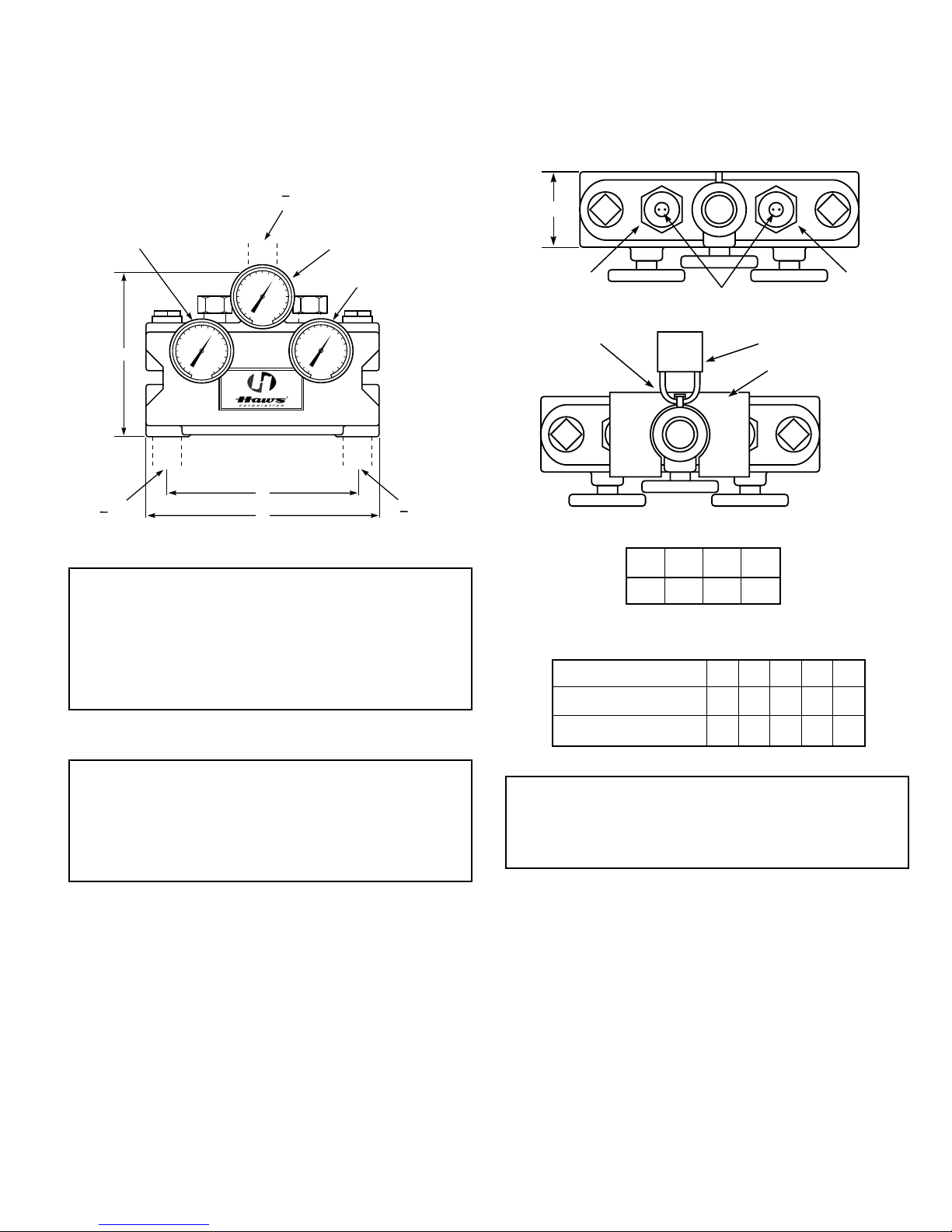
Caution: When maintaining and adjusting the mix-
D
V2V1
#3 CAP SCREWS
SAFETY LATCH #1 PADLOCK (optional)
#2 LOCKOUT PLATE
(optional)
30
40
50
60
70 80
90
110
120
130
30
40
50
60
70 80
90
110
120
130
30
40
50
60
70 80
90
110
120
130
1 w
4
N.P.T.
COLD
INLET
N.P.T.
HOT
INLET
1 w
4
A
B
C
1
1
N.P.T. TEMPERED
OUTLET
1 w
4
1
T2
T3
T1
ing valve, the delivered flushing fluid temperature
shall be 60°F (15°C) to 95°F (35°C). In circumstances where chemical reaction is accelerated
by flushing fluid temperature, a medical advisor
should be consulted for the optimum temperature
for each application.
DIMENSIONS:
A B C D
11″ 9″ 8″ 41/4″
CAPACITIES
Pressure Drop PSI 5 10 20 30 45
Tempered Flow
25 35 50 60 72
Setting the Mixing Valve
Caution: When maintaining and adjusting the
mixing valve, all fixtures should be isolated from
use. We recommend that you work safely at all
times and in a manner consistent with the OSHA
Lock/Tagout standard, 29 CFR 1910.147 and other
applicable standards.
This mixing valve has been set at the factory to
deliver 85°F outlet flow. Should the valve require
adjustment, or an application require a different set
temperature, proceed as follows:
1. Contact the proper medical and safety authorities
to determine correct water temperature for the
specific application.
Cold Water Bypass
14 20 28 40 45
Note: Valve must be installed with check valves. If
shut off valves are installed in the shower line for
maintenance purposes, provisions shall be made
to prevent unauthorized shut off.
2. If the valve is outfitted with a padlock #1 and
lockout plate #2, unlock and remove.
3. Use a spanner wrench to remove the tamperresistant cap screws #3.
4. Create a draw on the mixing valve by opening a
downstream shower fixture.
Page 2 of 7
Page 3
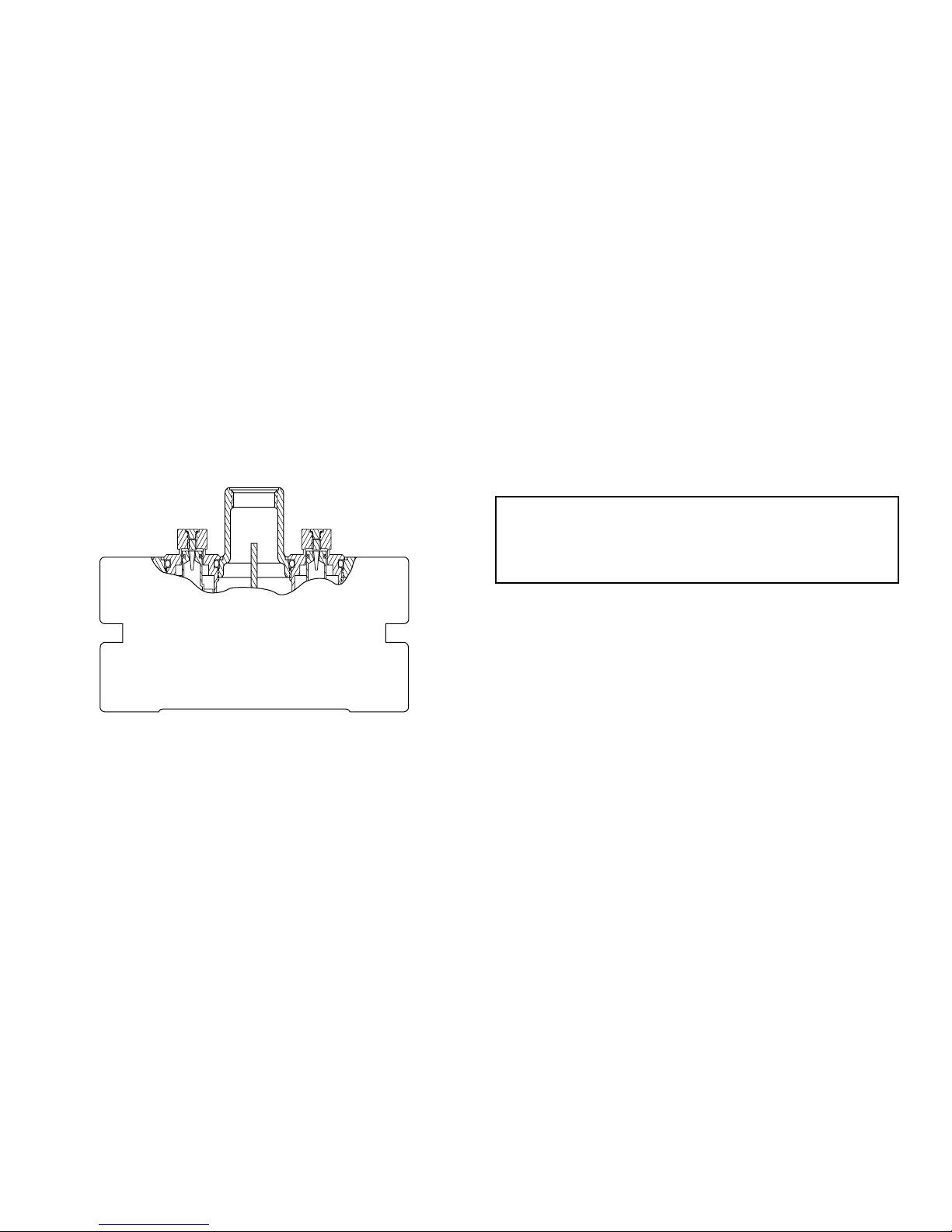
5. Insert a 5/32″ allen key into the cap opening of
valve 1 (V1) and seat in the adjustment screw
(not shown). Set the outlet temperature by turning the adjustment screw-clockwise to reduce
temperature, counterclockwise to increase temperature. Use thermometer (T1) to measure the
outlet temperature.
6. Adjust valve 2 (V2) using the same procedure
used to adjust valve 1 (V1).
7. Examine thermometers T1 and T2. Valve 1 and
valve 2 should be set to the same temperature
and the outlet temperature should be 85°F
or as specified for your application. Adjust if
necessary.
8. Replace cap screws #3, lockout plate #2 and
padlock #1.
Testing the Mixing Valve
The mixing valve and the emergency fixtures it serves
should be tested weekly for proper operation.
2. Shut off the hot water supply to the mixing valve.
Observe the outlet flow from the emergency fixtures to ensure an adequate flow of cold water.
A slight drop in flow may occur after shutting
down the hot water supply to the mixing valve;
however, the drop should be minimal and for a
short duration.
3. Open the hot water supply to the mixing valve.
Thermometers T1 and T2 should return to their
set temperatures and T3 to the proper outlet
temperature.
4. Shut off the cold water supply to the mixing valve.
The flow of water should shut down rapidly.
5. Open the cold water supply. Thermometers T1
and T2 should return to their set temperatures
and T3 to the proper outlet temperature.
Note: Thermometers T1, T2, and T3 should be
checked at least every six months.
Replacing a Thermostat Cartridge
Valve 1
(V1)
Valve temperature test procedure is as follows:
1. Activate shower fixtures to observe and record
the temperature of the thermometers T1, T2, and
T3. The valve is functioning properly if the T1
and T2 temperatures are equal and T3 is at the
proper outlet temperature. If the temperature of
thermometers T1 and T2 are not equal, readjust
the mixing valve according to the section “Setting
the Mixing Valve.” Slight variations between the
valve set temperatures and the outlet temperatures may occur.
2. Observe the flow from the emergency fixtures to
ensure an adequate flow of water.
In addition to testing for proper temperature, the cold
water by-pass and hot water shut down features of
the mixing valve should be tested weekly.
The test procedure is as follows:
1. Test valve temperature as described in Step 1
and Step 2 above.
Valve 2
(V2)
The thermostat replacement procedure is as follows:
NOTE: We recommend that you work safely at all
times and in a manner consistent with the OSHA
Lock/Tagout standard, 29 CFR 1910.147 and other
applicable standards.
1. Shut off the hot water supply and cold water
supply to the mixing valve.
2. Unscrew valve V1 or V2 (depending on which
valve is not operating properly) and install a new
thermostat cartridge assembly.
3. Open the hot water supply and the cold water
supply to the mixing valve. Check the temperature to see if the replacement cartridge is
operating correctly. If the temperature requires
adjustment refer to the section “Setting the Mixing Valve.”
Operating Principle
The Mixing Valve is made of two independent
thermostats housed in a single casting. The twin
thermostatic cartridges respond independently to
incoming hot and cold water temperatures and
provide backup protection against element failure.
If one element fails, the other should continue to
function properly. If only one element is operating the valve will experience a decrease in outlet
temperature (T3). For this reason the Valve requires testing and maintenance on a regular basis.
In the event of element failure, the cartridge will
provide full cold water flow. The resulting temperature
difference between the two valves will be reflected
by T1 and T2.
Page 3 of 7
Page 4
Installation
Water
Heater
Storage
Tank
Check Valve (TYP.)
To Low
Temperature
Fixtures
Mixing Valve
CW
A
B
Heat Trap
27″ Drop
30
40
50
60
70 80
90
110
120
130
30
40
50
60
70 80
90
110
120
130
30
40
50
60
70 80
90
110
120
130
C
Recirculating Pump
Water
Heater
Storage
Tank
Check Valve (TYP.)
To Low
Temperature
Fixtures
Mixing Valve
CW
A
B
Heat Trap
27″ Drop
30
40
50
60
70 80
90
110
120
130
30
40
50
60
70 80
90
110
120
130
30
40
50
60
70 80
90
110
120
130
C
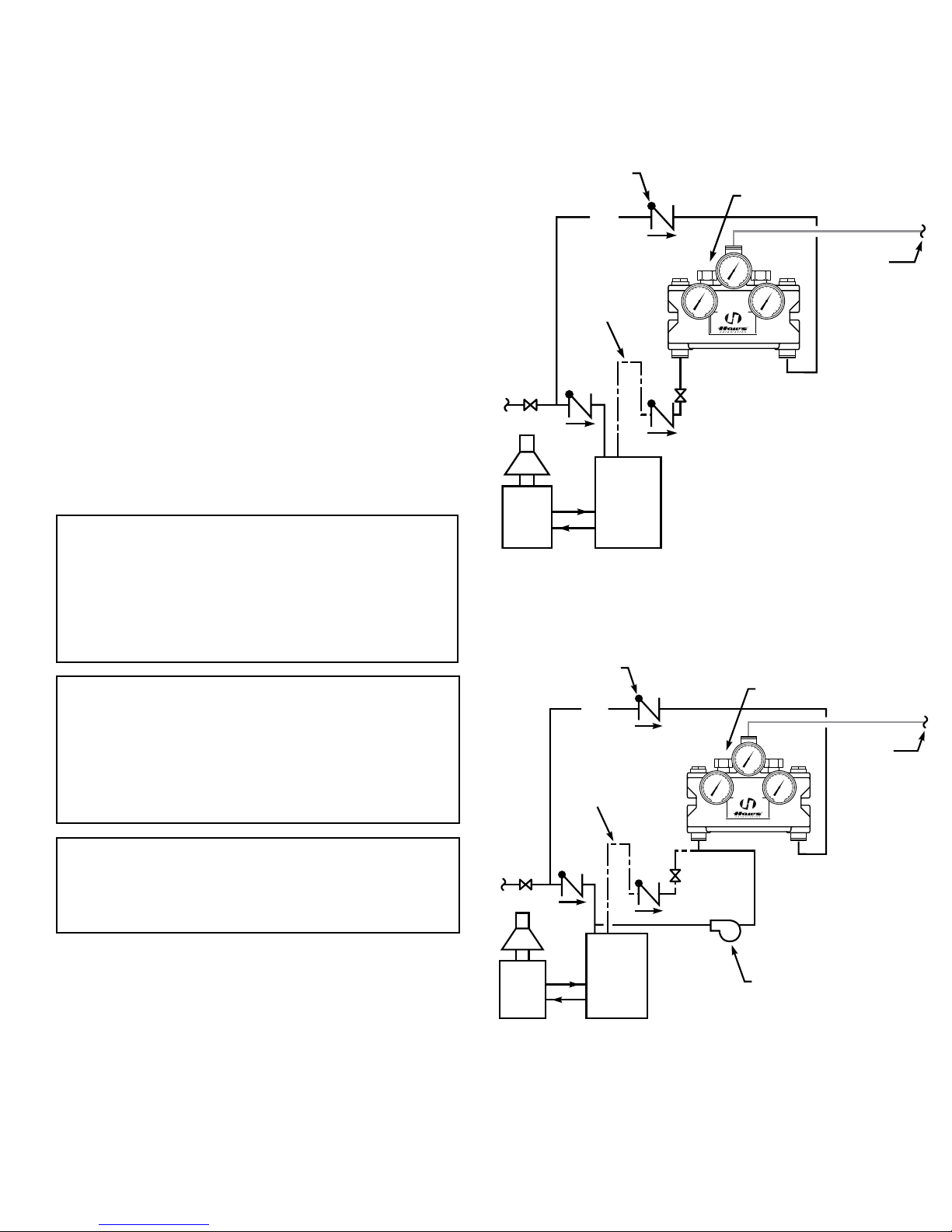
After installing the mixing valve, be sure to flush
the system thoroughly. We recommend isolation and
check valves for proper maintenance.
Typical Installation Figure 1
When installed at or near the water heater and without a recirculation system:
Install the valve as shown in Figure 1 with the mixing
valve positioned below the hot water tank or heater. If
this is not possible, pipe in a heat trap as shown.
Typical Installation Figure 2
When installed away from the water heater with a
recirculating pump on the hot water supply line:
Note: If the valve is installed 20 feet or more from
the water heater, it is important to recirculate the hot
water supply to the mixing valve.
Install the mixing valve as shown in Figure 2. The noncirculated loop should be limited to 10 feet and must
be flushed periodically.
Figure 1
Typical installation. Valve must be
installed with check valves.
Caution:
that it is not affected by excessively hot ambient temperatures. An example of hot ambient temperature
is a long run of pipe exposed to direct sunlight. Cold
water pipe installed in the ceilings of boiler rooms
or rooms that increase ambient temperature require
a recirculating pump.
Caution: When maintaining and adjusting the
mixing valve, the delivered flushing fluid temperature shall be 60°F (15°C) to 95°F (35°C). In circumstances where chemical reaction is accelerated
by flushing fluid temperature, a medical advisor
should be consulted for the optimum temperature
for each application.
Note: Gallon per minute ratings may vary depending upon incoming water temperatures and
pressures. Hot and cold water inlet pressures
must be equal.
Maximum Inlet Pressure: 125 PSI.
Recommended Supply Pressure: 65 PSI.
Recommended Inlet Temperature: 120°F.*
*When supplying 140°F or greater, additional outlet
controls should be used.
The cold water line must be installed so
Figure 2
Typical recirculating installation. Valve
must be installed with check valves.
Page 4 of 7
Page 5
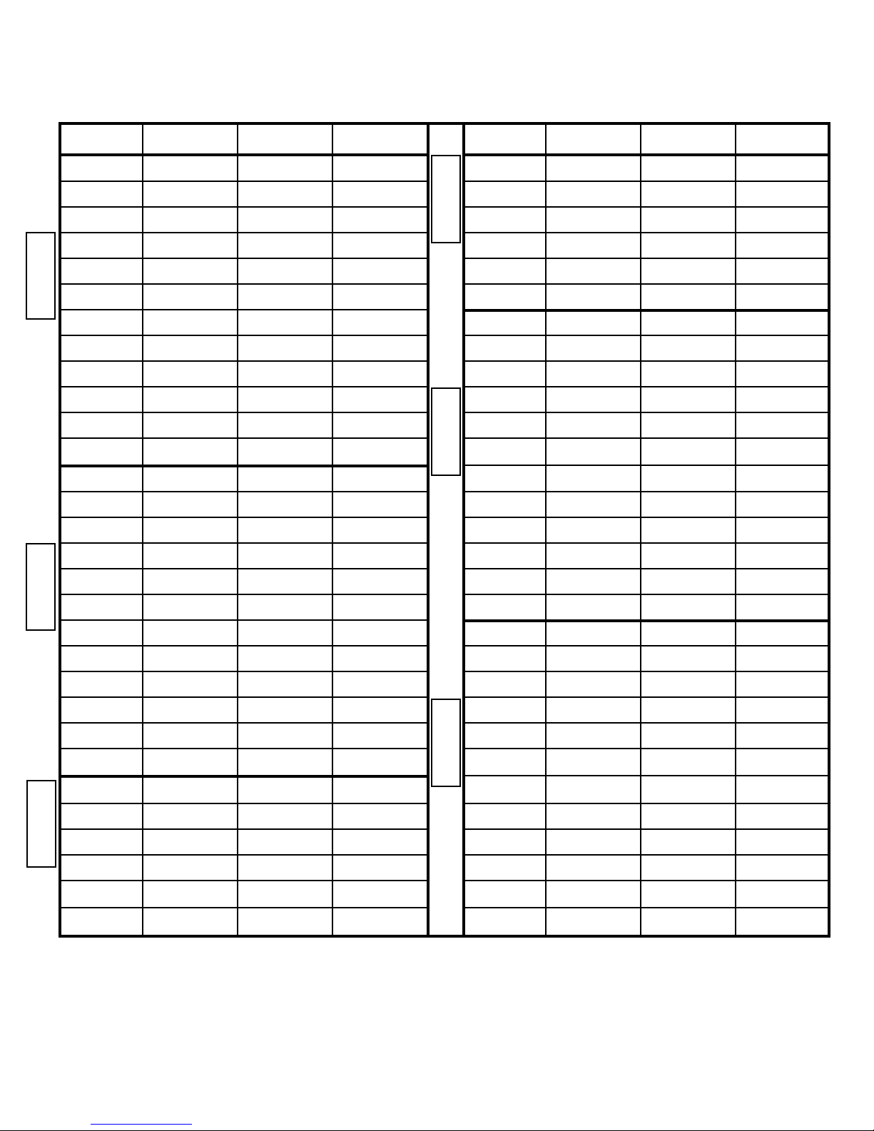
Test Record
Location _______________________
Date T1 T2 T3
Jan
Feb
March
April
May
June
July
Aug
Sept
YEAR
Oct
Nov
Dec
Jan
Feb
March
April
May
June
Date T1 T2 T3
July
Aug
Sept
Oct
Nov
Dec
YEAR
Jan
Feb
March
April
May
June
July
Aug
Sept
YEAR
Oct
Nov
Dec
July
Aug
Sept
YEAR
Oct
Nov
Dec
Jan
Feb
March
April
May
June
YEAR
Before you use this chart please make a copy for future testing records.
Caution: When maintaining and adjusting the mixing valve. The delivered flushing fluid temperature shall
be 60°F (15°C) to 95°F (35°C). In circumstances where chemical reaction is accelerated by flushing fluid
temperature, a medical advisor should be consulted for the optimum temperature for each application.
Jan
Feb
March
April
May
June
July
Aug
Sept
YEAR
Oct
Nov
Dec
Page 5 of 7
Page 6
Page 7
 Loading...