

Page 1
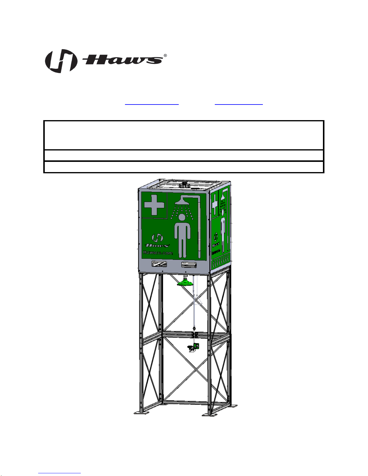
Overhead Tank Shower and Optional Eye/Face Wash
Non-Electric, Self-Contained, Indoor, Gravity Fed
INSTALLATION, OPERATION
&
MAINTENANCE INSTRUCTIONS
1455 Kleppe Lane Sparks, NV 89431-6467 (775) 359-4712 Fax (775) 359-7424
E-mail: haws@hawsco.com Website: www.hawsco.com
No. 0510000842(1)
Model 8740 / 874301S
HAWS® P/N 0510000842 Rev.1 06/18 Model 8740 / 874301S Page 1 of 33
Page 2

IMPORTANT
Read this installation manual completely to ensure proper installation, then file it with the owner or
maintenance department. Compliance and conformity to drain requirements and other local codes and
supply to the
and a minimum fill flow rate of 15 GPM for the
ordinances is the responsibility of the installer.
Separate parts from packaging and make sure all parts are accounted for before discarding any
packaging material. If any parts are missing, do not begin installation until missing parts are obtained.
Flush the water supply lines before beginning installation and after installation is complete. Test the unit
for leaks and adequate water flow. For ANSI Z358.1 compliance, the main water
emergency fixture s hould be “ON” at all times. Prov isions should be made to prevent u nauthorized
shutoff.
The ANSI Z358.1 stand ard requires a 20 GPM flow rate for the shower and a 3 GPM flow rat e for the
optional Eye/Face Wash of flushing fluid f or 15 continuous minutes. Ha ws Model 8740 self-contained
shower requires a minimum fill pressure of 20 PSI
shower only or 20 GPM for shower and optional Eye/Face Wash combination at the automatic refill
connection to meet this requirement. Flushing fluid should be tepid per ANSI Z358.1. Haws Model 8740
should be installed in an indoor area that has an ambient temperature between 60°F and 100°F to meet
this tepid water requirement.
The tank water level should be checked weekly to ensure that the tank is full. For ANSI Z358.1
compliance, the automatic refill connection must be connected to an adequate potable water source.
This unit discharges water to the floor. It is recommended that this unit be installed in an area that
has adequate floor drainage. Failure to do so may result in major property damage.
HAWS® P/N 0510000842 Rev.1 06/18 Model 8740 / 874301S Page 2 of 33
Page 3

DESCRIPTION OF PRODUCT
Haws Corporation Model 8740 non-electric, self-contained overhead tank shower and optional Model
874301S Eye/Face Wash is des igne d for us e in in door ar eas where the temper ature is norm ally between
60°F and 100°F. The 330-gallon high density polyethylene (HDPE) overhead tank is discharged by gravity
upon shower or optional Eye/Fac e Wash activation. The unit is equipped with a 1-1/4” NPT inlet water
connection and float valve for automatic refill.
The unit is designed to m eet ANSI Z358.1 s tandards for flow and duration if it is connected to a suit able
permanent potable water source. Haws Model 8740 self-contained shower requires a minimum fill pressure
of 20 PSI and a minimum fill flow rat e of 15 GPM for the sho wer only or 2 0 GPM for shower and optional
Eye/Face Wash combination at the autom atic r efill con nection to m eet this require m ent. Water should be
tepid per ANSI Z358.1. Haws Model 8740 should be installed in an indoor area that has an ambient
temperature between 60°F and 100°F to meet this tepid water requirement.
The optional Model 874301S Eye/Face W ash available for this unit uti lizes Haws Axion MSR (Medically
Superior Response®) eyewash design. The AXION MSR Eye/Face Wash uses an inverted stream design
which sweeps chem ical and particulate contaminants away from the vulnerable nasal ca vity, consistent
with medical irrigation protocols.
Although optional, the Model 9084 is recommended for use with the Mod el 8740. T he Model 9084 is an
immersible Cleansin g Stick that gives continual protection against path ogenic bacteria for water storage
systems. It balances the PH of the water preventing the build-up of bio-film, scale, and corrosion for up to
3 years with proper usage.
HAWS® P/N 0510000842 Rev.1 06/18 Model 8740 / 874301S Page 3 of 33
Page 4

Model Description
Haws Overhead
Tank Shower
SHIPPING, HANDLING AND STORAGE
Dimensions
W x L x H
(Assembled)
Dry Weight
Filled (Wet)
Weight
Dimensions
W x L x H
(Shipping)
Weight
(Crated)
8740
55” x 59” x 150” 975 lbs. 3750 lbs. 60” x 49” x 79” 1025 lbs.
Recommended Equipment, Materials, and Supplies to be provided by Installer:
• Existing slab on grade. T he installer shall verif y that the following minimum requirements of the
existing slab-on-grade are satisfied.
o Allowable Soil Bearing Pressure: 1500 psf
o Slab-on-grade minimum thickness: 6 inches
o Compressive Strength of slab, f’c: 3000 psi
o Adequate footprint area (minimum 6’ x 6’ recommended)
o Adequate vertical space (minimum 14.5 ft. recommended, 13 ft. required)
• Recommended anchors (Not Included, customer to determine anchor suitability):
High strength adhesive anchors (ICC-ES Report ESR-3187): Hilti HIT-HY 200 Safe Set epoxy
adhesive anchorage s ystem and Hilti h ollow drill bit system with 5/8” d iameter Hilti HIT-Z Rod, 2
ASTM F844 flat washers , and AST M A563 Grade A nuts. Frame Feet mounting holes are 13/16”
diameter. Hilti specifies 3-3/4” m inim um embedment depth per HIT-Z specif ications. F rame F eet
have four (4) 13/16” diameter clearance holes (16 total anchors).
• A forklift capable of lifting 2,000 lbs. should be utilized to transport the unit from truck to site and to
lift tank into position.
Tools and Supplies
• Impact drill/driver with 5/16” nut driver (For Optional Eye/Face Wash Option).
• Steel Strap Shears
• Torque wrench with 7/8” and 9/16” sockets.
• 7/8” and 9/16” box end wrenches.
• Plumbing supply materials including potable water-safe thread sealant for PVC.
(Automatic refill water connection is 1-1/4” NPT male pipe fitting.)
• Appropriate personal protective equipment including safety glasses and work gloves.
Storage
The unit should be stored in a clean, dry place until ready for installation.
HAWS® P/N 0510000842 Rev.1 06/18 Model 8740 / 874301S Page 4 of 33
Page 5
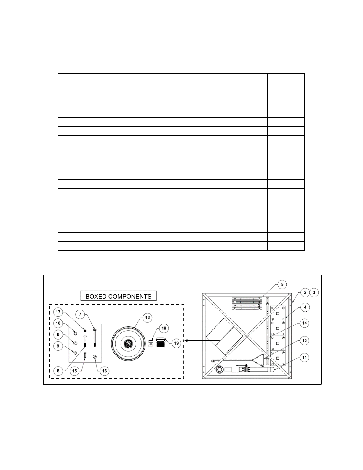
PALLET CONTENTS
ITEM #
DESCRIPTION
QUANTITY
1
Tank Assembly
1
2
Frame Back Panel
2
6
½-13 X 3” Bolt
16
7
½-13 X 5” Bolt
16
8
½” Flat Washer
64
9
½” Lock Washer
32
10
½-13 Nut
32
11
Shower Piping Assembly
1
12
Shower Head
1
17
3/8-16 Nut
2
18
1-1/2” Strut Pipe Clamp Assembly (2 straps, 1 bolt, 1 nut)
1
19
Tank Breather Vent, 2” NPT
1
NOTE: Confirm all components listed for the Model 8740 are present before assembly. See Figure 1.
(For optional Model 874301S Eye/Face Wash Assembly components see page 21.)
3 Frame Side Panel 4
4 Frame Feet 4
5 Frame Connection Bars 4
13 Shower Pull Rod 1
14 1-5/8” x 38” Steel Strut 1
15 3/8-16 X 1-1/4” Bolt 2
16 3/8” Flat Washer 4
Figure 1. Pallet Contents Model 8740; Item #1 Tank Assembly Removed
HAWS® P/N 0510000842 Rev.1 06/18 Model 8740 / 874301S Page 5 of 33
Page 6
MODEL 8740 ASSEMBLY & INSTALLATION PROCEDURE
1. Transport the p allet ized uni t to the install ation po int via f o rk lift, ensuring the forks are ins er ted through
the shipping pallet.
2. The installation area should be located indoors on a level floor capable supporting up to 4,000lbs spread
across the four Frame Feet. Suitable concrete flooring is preferred. If unit is to be placed over a drain,
the drain should be able to handle a flow of 35 GPM; otherwise, the slab should allow the water to drain
away from the unit.
3. Confirm there is suitable available vertical space where the unit is to be installed . T he unit r equ ires a
minimum of 13ft vertical space for installation, 13.5ft of vertical space for assembly, and 14.5ft of vertical
space to insert or remove the optional Model 9084 Cleansing Stick if utilized.
4. Remove the plastic wrap packaging around the palletized unit.
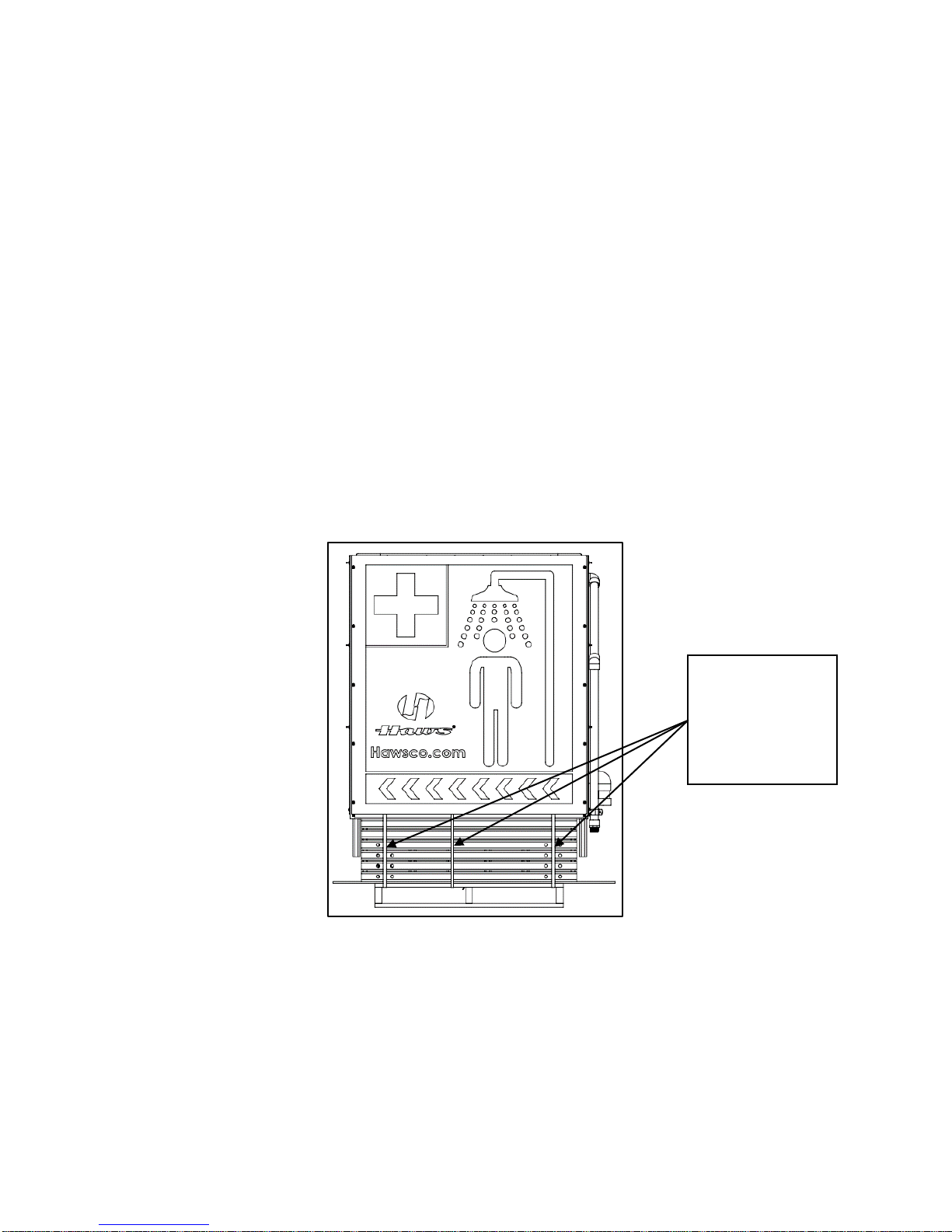
5. Cut the three (3) steel bands that st rap the unit to the wooden pal let as shown in Figure 2. DO NOT
cut the steel bands on top of the tank ass em bly (th ese 4 bands retain the tank on the tank fram e and
will not be removed).
Cut and remove
three steel bands
that strap the unit
to the wooden
pallet ONLY.
Figure 2. Removing 3 Steel Bands
6. Use a forklift to lift the Tank Assembly (Item #1) from the palletized unit, using the fork slots on the Tank
Assembly, and set the Tank Assembly aside.
7. Remove box of com ponents from the pallet and rem ove components from the box. Next, remove
shipping screws/washers holding frame components to pallet. Discard shipping/screws. Place all
components in a secure area until needed.
HAWS® P/N 0510000842 Rev.1 06/18 Model 8740 / 874301S Page 6 of 33
Page 7
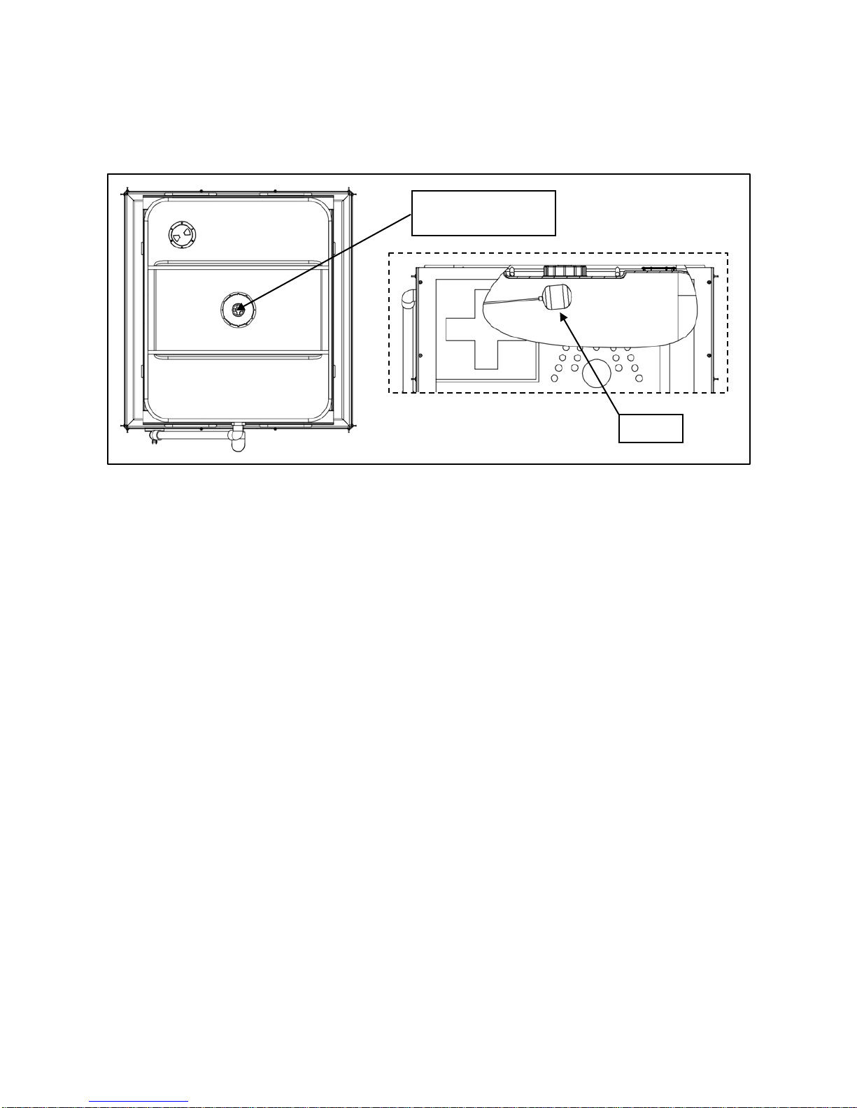
8. At the top of the tank, remove t he shipping plug from top cap and c ut cable tie holding the float f or
Remove shipping
plug & cut cable tie
Float
shipping protection. Ensure the cable tie does not drop into the tank. See Figure 3.
Figure 3. Remove Shipping Plug and Detach Shipping Protection for Float
HAWS® P/N 0510000842 Rev.1 06/18 Model 8740 / 874301S Page 7 of 33
Page 8
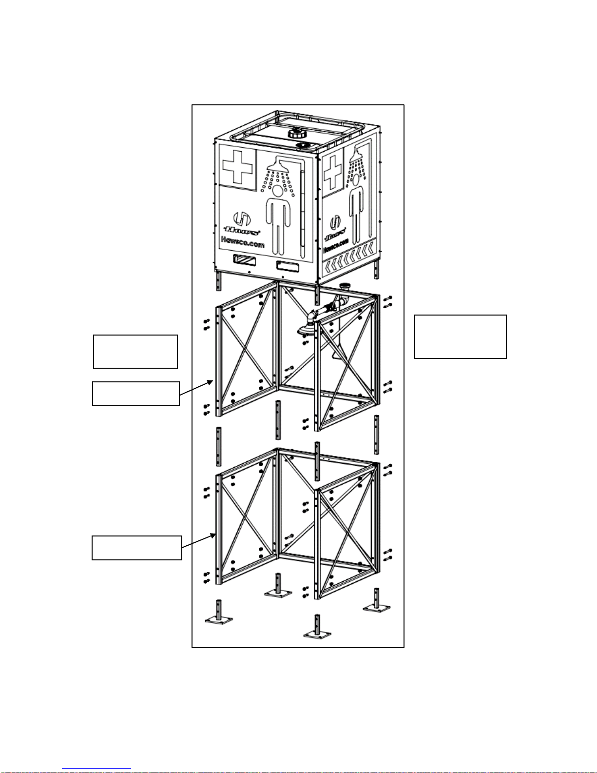
9. Figure 4 shows an exploded view of the assembly.
IN FRONT
5-INCH BOLTS
BACK PANEL
3-INCH BOLTS
UPPER FRAME
LOWER FRAME
USED FOR
HAWS® P/N 0510000842 Rev.1 06/18 Model 8740 / 874301S Page 8 of 33
Figure 4. Exploded View of Model 8740
Page 9
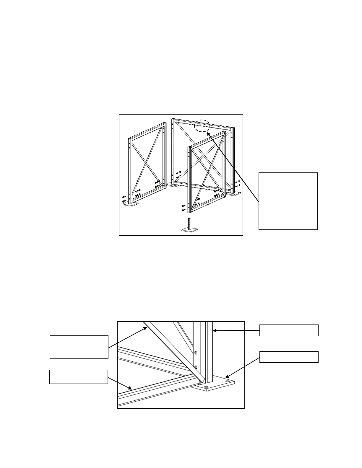
10. Begin by assembling the lower f rame shown in Figure 5. With all four (4) Fram e Feet present, place
Frame Back Panel
Frame Foot Plate
Frame Side Panel
one Frame Back Panel over two back Frame Feet posts. Holes must be aligned front to back and panel
cross-bracing strips must be on the outs i de (toward the back) as shown in Figure 5.
IMPORTANT!! The two (2) mounting ho les must be oriented as shown in Figure 5 to ensur e unit can
accept optional Model 874301S Eye/Face Wash in the future.
IMPORTANT!!
Two Eye/Face
Wash mounting
holes must be
located here on
the lower frame
assembly!
Figure 5. Lower Frame
11. Place one (1) Frame Side Panel over each of the t wo (2) front Frame Feet posts with the panel crossbracing strips to the outside as shown in Figure 5.
12. Set the back of each of the two (2) Side Frame Panels on the Frame Feet plates of the Back Panel with
the mounting holes aligned as sho wn in Figure 6. Confirm the pane l cross-bracing strips are on the
outside.
Cross-Bracing
Strips
Figure 6. Frame Side Panel on Back Frame Foot
13. Typical bolting arrangement is shown in Figure 7 for reference in the next steps.
HAWS® P/N 0510000842 Rev.1 06/18 Model 8740 / 874301S Page 9 of 33
Page 10
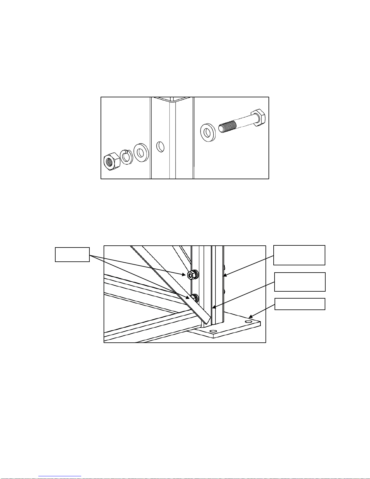
• 5” bolting is for attachment of back panels through feet or connectors to side panels and 3” bolting
Frame Back
Panel
Frame Foot
Frame Side
Panel
5-INCH
is for side panels through connectors or feet only.
• Bolting should consist of one 1/2-13 x 5” bolt (Item #7) or 1/2-13 x 3” bolt (Item #6), two 1/2” flat
washers (Item #8), one 1/2” lock washer (Item #9), and one 1/2-13 nut (Item #10).
Figure 7. Typical Bolting Ar rangement (3” Bolt Shown)
14. With mounting holes aligned as shown in Figure 8, place four (4) each 5” bolts from back to front in the
lower frame holes only to secure Frame Side Pa nels to Fr am e Back Panel and Frame Feet. Refer to
Figure 7 for bolting arrangement.
Figure 8. Connecting Frame Side Panels to Frame Back Panel
HAWS® P/N 0510000842 Rev.1 06/18 Model 8740 / 874301S Page 10 of 33
Page 11

15. Place four (4) eac h 3” bolts from front to back in the front portion of lower Fr ame Side Panel holes to
Frame Foot
Frame Side Panel
secure the front Frame Feet as shown in Figure 9. Refer to Figure 7 for bolting arrangement.
3-INCH
Figure 9. Securing Side Panels to Frame Feet
16. Install the Fram e Connection Bars (Item #5) as show n in Figure 10 by inserting two (2) bars in the
Frame Back Panel an d one (1) bar in the front por tion of each F rame Side Panels. Align the bottom
two holes of the bars with top two holes of the frame panels and bolt in place wi t h four (4) total 5” bolts
in the back and four (4) total 3” bolts in the front. Refer to Figure 7 for bolting arrangement.
5-INCH
3-INCH
HAWS® P/N 0510000842 Rev.1 06/18 Model 8740 / 874301S Page 11 of 33
Figure 10. Installing Frame Connection Bars
Page 12

17. Next, build the up per fr ame assem bly. Form the upper frame as sembly by placi ng the back and side
frame panels as shown in Figure 11. Verify the cross-bracing strips on each panel are to the outsi de
of the assembly, and bolt together with four (4) each 5” bolts f rom back to front in th e bottom of the
frame, finger-tight. Refer to Figure 7 for bolting arrangement.
NOTE: These bolts are installed temporarily and will need to be removed and reinstalled in a future step.
IMPORTANT!! The two (2) mounting holes must be orient ed as shown in Figure 11 t o ensure unit can
accept optional Model 874301S Eye/Face Wash in the future.
IMPORTANT!!
Two Eye/Face
Wash mounting
holes must be
5-INCH
located here on
the upper frame
assembly!
5-INCH
Figure 11. Installing Lower Bolts (5-inch) Temporarily to Form Upper Frame Assembly
IMPORTANT!! Ensure the cabl e tie (shi pping float suppor t) is cut and shippi ng p lug is removed from the
6” cover on the top of the tank . Ins pect th e floa t and conf irm the f loat is firm l y installed on the f loat valv e.
Inspect the inlet p iping for an y shipping dam age and inspec t the bulkhead f itting where the float valv e is
installed. It is better to address any concerns about the tank before it is on top of the frame
IMPORTANT!! Haws strongly recommends the use of the Haws Model 908 4 Cleansing St ick to provide
prolonged (up to 3 years) water treatment for the wat er in this tank. If this product has been purc hased,
install it in the tank now. Instructions for install ati on loc ated on page 26.
HAWS® P/N 0510000842 Rev.1 06/18 Model 8740 / 874301S Page 12 of 33
Page 13

18. Install Tank Breather Vent (Item #19) where the s hipping plug was located in the 6” cap as shown in
Figure 12.
Breather
Vent
Figure 12. Installing Breather Vent (Item #19)
HAWS® P/N 0510000842 Rev.1 06/18 Model 8740 / 874301S Page 13 of 33
Page 14

19. Use a suitable forklift t o lift the Tank Assem bly (Item #1) over the upper fram e assem bly as shown in
WARNING: Never place fingers, hands, or any other body part between upper
frame assembly and Tank/Tank Frame Assembly while installing the unit!
Figure 13. Carefully align and insert the tank frame legs into the upper frame assembly while carefully
lowering the tank.
WARNING:
Never place fingers,
hands, or any other
body part between
Tank Assembly and
upper frame assembly
while installing the unit!
Figure 13. Setting Tank Assembly on Upper Frame
HAWS® P/N 0510000842 Rev.1 06/18 Model 8740 / 874301S Page 14 of 33
Page 15

20. Use the forklift as needed to align bolt holes and install four (4) each 5” bolts from back to front through
WARNING: Never place fingers, hands, or any other body part between upper
frame assembly and Tank Assembly while installing the unit!
Back Frame Panel and Sid e Fram e Panels and four ( 4) each 3” bolts from front to back of the F rame
Side Panels as shown in Figure 14. Refer to Figure 7 for bolting arrangement.
3-INCH
Figure 14. Bolting the Tank Assembly to the Upper Frame
5-INCH
HAWS® P/N 0510000842 Rev.1 06/18 Model 8740 / 874301S Page 15 of 33
Page 16

21. Use two (2) each 3/8-16 X 1-1/4” bolts (Item #15) to install Steel Strut (Item #14) to the underside of
Steel
Strut
the two (2) tabs under the Tank Assembly as shown in Figure 15. The 1-1/4” bolting should consist of
one 3/8-16 X 1-1/ 4” bolt (Item #15), two 3/8” Flat Washers (Item #16), and one 3/8-16 Nut (I tem #17).
The open side of the channel should face dow n. Tight en the t wo (2) bolts with a tor que wr ench t o 23
ft-lb.
Figure 15. Mounting Steel Strut for Shower Piping (Side Frame Panels Not Shown for Clarity)
3/8 Bolts
HAWS® P/N 0510000842 Rev.1 06/18 Model 8740 / 874301S Page 16 of 33
Page 17

22. Install the Shower Piping Assembly (Item #11) from the back of the shower by threading the union nut
Union
Nut
on the assembly to the union end on the tank as shown in Figure 16.
Figure 16. Installing the Shower Pipe Mount Steel Strut and Shower Piping Assembly to the Tank Union
HAWS® P/N 0510000842 Rev.1 06/18 Model 8740 / 874301S Page 17 of 33
Page 18

23. Remove the nut and bolt from the 1-1/2” Strut Pipe Clamp Assembly (Item #18), insert the two (2) clamp
Elbow
halves onto the Shower Pipe Mou nt Steel Str ut ( It em #14) around either si de of the s ho wer pi pe, and
re-install the clamp bolt and nut as shown in Figure 17. Center the shower approximately, push elbow
closely toward s trut and tighten the bolt and nut until the sho wer pipe is h eld firm ly. (T ake c are to not
overtighten.)
24. Thread Shower Head (Item #12) onto end of Shower Piping Assembly. See Figure 17.
Strut Pipe
Clamp
Shower
Head
Figure 17. Strut Pipe Clamp Assembly and Shower Head/Bell
25. Remove the four (4) 5” bolts holding the bottom of the upper frame panels together that were previously
temporarily installed from Step 17. Reference Figure 11.
26. Confirm the lower frame is located as desired for long term installation.
HAWS® P/N 0510000842 Rev.1 06/18 Model 8740 / 874301S Page 18 of 33
Page 19

27. From the front, use the forklift to lift the Tank Assembly and upper frame assembly over the lower frame
WARNING: Never place fingers, hands, or any other body part between upper
frame assembly and Tank/Tank Frame Assembly while installing the unit!
WARNING:
while installing the unit!
assembly. Caref ully set the upper ha lf of the frame on the lower half of the frame over the four (4)
Frame Connection Bars.
Never place fingers,
hands, or any other
body part between
Tank Assembly/upper
frame assembly and
lower frame assembly
Figure 18. Mounting Tank Assembly and Upper Frame to Lower Frame
HAWS® P/N 0510000842 Rev.1 06/18 Model 8740 / 874301S Page 19 of 33
Page 20

28. Bolt the T ank Assembly and up per frame ass embly to the lower fram e assembly through t he Frame
Connection Bars as s hown in Figure 18. Use t he forklift as ne eded to align bolt holes. Replace the
four (4) 5” bolts removed in Step 27 from back to front through the Frame Back Panel and Frame Side
Panels of the upper frame assembly and install four (4) 3” bolts from front to back in the front mounting
holes of the Frame Side Panels. Refer to Figure 7 for bolting arrangement.
IMPORTANT!! Using a torque wre nch and 7/8” socket, tighten ALL 1/2-13 frame bolts to 100 ft-lbs.
3-INCH
5-INCH
Figure 18. Bolting Upper Frame Assembly to Frame Connection Bars in Lower Frame Assembly
29. Insert end of Shower Pull Rod (Item #13) through hole in Shower Piping Assembly ball valve handle.
30. Install suitable concrete anchors through mounting holes in Frame Feet per the manufacturer’s
instructions. Customer to determine anchor suitability.
HAWS® P/N 0510000842 Rev.1 06/18 Model 8740 / 874301S Page 20 of 33
Page 21

OPTIONAL MODEL 874301S EYE/FACE WASH ASSEMBLY (If Applicable)
ITEM #
DESCRIPTION
QUANTITY
1
Eye/Face Wash Piping Assembly
1
2
Eye/Face Wash Mount Steel Strut
2
3
½” Strut Pipe Clamp Assembly
2
4
½” NPT x 1/2” Nylon Hose Barb
1
5
¼” Fender Washer
4
6
#12-24 X 7/8” Self-Drilling Screw (5/16” Hex Head)
4
7
1/2” X 36” Flexible Tube
1
8
Push Flag
1
9
AXION MSR Eye/Face Wash Head
1
10
AXION MSR Eye/Face Wash Cover
1
11
Small Cable Tie
2
12
Large Cable Tie
1
PACKAGE CONTENTS
NOTE: Confirm all components for the Model 874301S listed are present before assembly. See Figure
19.
Figure 19. Eye/Face Wash Carton Contents
HAWS® P/N 0510000842 Rev.1 06/18 Model 8740 / 874301S Page 21 of 33
Page 22

MODEL 874301S ASSEMBLY PROCEDURE
Steel
Strut
Fender
Washer
Screw
1. Place one (1) Eye/Face Wash Mount Steel Strut (Item #2) approximately in the center of the lower bar
over the two Eye/Face W ash mounting holes as shown in Figure 20. The h oles are drilled, but not
tapped.
Figure 20. Eye/Face Wash Mount Steel Strut Placement
2. Place two (2) 1/4” Fender Washers (Item #5) over two (2) #12-24 X 7/8” Self-Drilling Screws (Item #6).
Work the fender washer/screw into either end of the strut. Use an impact driver with a 5/16” hex driver
to drive the self-dr ill ing screws into the mounti ng hol es through the slot in the strut as shown in Figure
21.
Self-Drilling
Figure 21. Washer and Screw Placement
HAWS® P/N 0510000842 Rev.1 06/18 Model 8740 / 874301S Page 22 of 33
Page 23

3. Repeat Steps 1 and 2 for second Eye/Face Wash Mount Steel Strut. Results shoul d res emble Figure
Step 8:
Wash Cover
Step 7:
Nut
Step 8:
Wash Head
22.
Figure 22. Two (2) Eye/Face Wash Mount Steel Struts Installed
4. Remove the nut and bolt f rom one 1/2” Str ut Pip e Cla m p Assem bly (Item #3) and work the two clam p
halves into the upper Eye/Face Wash Mount S tee l Stru t ( Item #2) by twisting them sidew a ys bet w een
the two screw heads.
5. Place the vertical pipe from the Eye/Face Wash Piping Assembly (Item #1) int o the clamp, then install
the bolt and nut into the clamp. Center the clamp in the strut and finger tighten the clamp as shown in
Figure 23.
6. Repeat step 4 with the sec ond 1/2” Strut Pipe Clamp As sembly, placing the clam p assembly in the
lower Eye/Face Wash Mount Steel Strut and around the Eye/Face Wash Piping Assembly.
Steps 4-6:
Strut Pipe
Hose Barb
Clamps
Eye/Face
Wash
Piping
Assembly
Eye/Face
Step 7:
Push Flag
Eye/Face
Figure 23. Eye/Face Wash Assembly (Frame Hidden for Clarity)
HAWS® P/N 0510000842 Rev.1 06/18 Model 8740 / 874301S Page 23 of 33
Page 24

7. Remove hex nut from ball valve handle, place Push Flag (Item #8) on val ve stem as shown in Figur e
23, then replace and tighten nut.
8. Place ring of Eye/F ace Wash cover (Item #10) over nipple on Eye/Face W ash Head (Item #9) and
install the head as shown in Figure 23.
9. Use a measuring tape to measur e the distance between t he floor and the top of t he Eye/Face W ash
head. Adjust the vertical location of the Eye/Face Wash Piping Assembly until the top of the Eye/Face
Wash head is approximately 40”. T ighten the bolts and nuts i n the two clam ps to hold the Eye/Face
Wash Piping Assembly firmly in place.
NOTE: This s hould res u lt i n an AN SI Z358.1 compliant stream height , ho we ver t h is s hou ld be t es ted and
adjusted after water supply is connected.
10. Carefull y push one e nd of the 1/2” X 36” F lexi ble T ube (Item #7) over the hose b arb on th e top of the
Eye/Face Was h Piping Assembly as shown in Figure 24. If necessary, the union at the top of the
Eye/Face Wash Piping Assembly can be l oosened and re-adjus ted to rotate the tu bing as required.
Place the natural be nd in t he tubing suc h that t he ben d is toward the back of the sho wer. Ref erence
Figure 26.
Flexible
Tube
Hose Barb
HAWS® P/N 0510000842 Rev.1 06/18 Model 8740 / 874301S Page 24 of 33
Figure 24. Attaching Flexible Tube
Page 25

11. Ensure there is no water in the overhead tank and remove the 1/2” NPT plug in the tee from the Shower
Piping Assembly directly above the Eye/Face Wash Assembly. Reference Figure 25.
12. Apply potable water safe thread sealant for PVC to the 1/2” NPT x 1/2” Nylon Hose Barb (Item #4) and
install the hose barb in the shower piping tee in place of the plug removed in Step 11.
13. Carefully push the loose end of the 1/2” X 36” Flexible Tube (Item #7) over the hose barb in the tee.
Hose Barb
Flexible
Tube
Figure 25. Removing Plug in Tee and Attaching Hose Barb/Flexible Tubing
14. Use two (2) Small Cable Ties (Item #11) to secure ends of the tubing on the barbs. See Figure 26.
15. Use the L arge Cable Tie (Item #12) to gently secur e the mid-section of the tubin g to the upper back
cross support straps on the Frame Back Panel of the upper frame. See Figure 26.
Cable Tie
Locations
Figure 26. Cable Tie Locations on Eye Wash
HAWS® P/N 0510000842 Rev.1 06/18 Model 8740 / 874301S Page 25 of 33
Page 26

OPTIONAL MODEL 9084 CLEANSING STICK (If Applicable)
The Model 9084 Cleansing Stick is shown in Figure 27.
Figure 27. Model 9084 Cleansing Stick
MODEL 9084 INSTALLATION PROCEDURE
1. Remove the thr eaded c ove r on th e Cleansing Stick access port in the front right c orner of the t ank as
shown in Figure 28. Tur n counter-clockwise to remove. Note the small hole through the center of the
cover.
Cleansing Stick
access port in front
right corner on top of
the tank.
Figure 28. Model 9084 Cleansing Stick Access Port Location
2. The Model 9084 Cleansing Stick comes with a retrieval str ing connec ted to one end. Mar k the str ing
approximately 17” from the connection point on the stick.
HAWS® P/N 0510000842 Rev.1 06/18 Model 8740 / 874301S Page 26 of 33
Page 27

3. From the underside of the cover, pass the end of the Cleansing Stick retrieval string through the small
String
hole in the middle. See Figure 29.
Access Port
Cover
Hole for
Retrieval
Figure 29. Access Port for Cleaning Stick
4. Tie a knot in the string on the top side of the cover at the 17” mark on the string.
5. Place the Cleansing Stick through the hole into the tank. The end of the Cleansing Stick must rest on
the bottom of the tank as shown in Figure 30. This mounting provision prevents the Cleansing Stick
from obstructing the tank outlet or automatic refill float valve.
Figure 30. Model 9084 Cleansing Stick Installed
6. Reattach cover and t hr ead c losed. Follo w the i nstr uc ti ons that comes with the Model 90 84 C le ans ing
Stick for maintenance and replacement intervals.
NOTE: For more information, refer to the Model 9084 Cleansing Stick, 2000 Liter O&M manual.
HAWS® P/N 0510000842 Rev.1 06/18 Model 8740 / 874301S Page 27 of 33
Page 28

CONNECTING THE MODEL 8740 AUTOM ATIC REFILL VALVE TO A POTABLE WATER SOURC E
The Model 8740 is equ ippe d with a 1-1/ 4” m ale NPT fitting (Figure 31) on t he fill pipe located on the b ack
of the unit. This pipe should be connected to a permanent potable water source. To meet the ANSI Z358.1
standard for flow a nd dur ati on, the unit requires a minim um f ill pr es sur e of 20 PSI and a m inimum fill flow
rate of 15 GPM for the shower only or 20 GPM for shower and optional Eye/Face Wash combination at the
automatic refill connection. Pressure should not exceed 60 PSIG. Use a pressure reducing device if
necessary.
Figure 31. Model 8740 Automatic Refill Port Location on Back of Unit
IMPORTANT! 60 PSIG
Maximum Inlet Pressure
1-1/4” NPT Male Water
Connection Fitting to Automatic
Refill Float Valve in Tank.
For ANSI Z358.1 compliance,
a minimum 20 PSI fill pressure
and a minimum fill flow rate of
15 GPM for the shower only or
20 GPM for shower and
optional Eye/Face Wash
combination at the automatic
refill connection is required.
HAWS® P/N 0510000842 Rev.1 06/18 Model 8740 / 874301S Page 28 of 33
Page 29

FILLING THE MODEL 8740 TANK WITH POTABLE WATER
1. Connect a suitable sourc e of potabl e water to the inlet connection on the back of the unit as shown in
Figure 31.
IMPORTANT!! For ANSI Z358.1 compliance, the m ain water supp ly to the em ergency fixture sho uld be
“ON” at all times. Provisions should be made to prevent unauthorized shutoff. Refer to your facility’s lockout
tagout procedure.
2. Ensure the shower (and Eye/Face Wash if equipped) valves are closed.
3. Turn on the water source and monitor the water level in the tank via the slot in the front tank panel.
4. If little or no water enters the tank, confirm the shipping protection strap on the float valve was properly
removed during assembly.
5. Allow the tank to fill. The float valve in th e tank wil l automatically shut off the flow as the water level
approaches the top of the tank. The tank should not fill completely to the top or exit the vent on the top
of the tank.
6. Check the inlet piping, tank, and shower piping for leaks and address as required.
7. If the optional Eye/Face Wash assembly has been instal led, chec k for leak age in the hose and piping
to the unit before and after activating the Eye/Face Wash.
TESTING THE INSTALLATION
1. With the tank full of water, pull the s hower activa tion handle. It is recomm ended to stand be hind the
unit to avoid drenching of the shower.
2. Confirm the handle pulls smoothly, but firmly both on and off .
3. Confirm the shower flows freely and shuts off completely. If water does not flow or flow freely, confirm
the tank ball valve at the tank outlet is fully open (handle parallel to pipe).
IMPORTANT!! For ANSI Z358.1 compliance, the m ain water supp ly to the em ergency fixture sho uld be
“ON” at all times. Provisions should be made to prevent unauthorized shutoff. Refer to your facility’s lockout
tagout procedure.
4. If the optional Eye/Face Wash assembly has been installed, push the Eye/Face Wash activation flag.
5. Confirm the Eye/Face Wash assembly actuation flag moves smoothly on and off.
6. Confirm the Eye/Face Wash flows freely and shuts off completely.
7. Confirm the automatic refill functions properly and that the tank is refilled.
HAWS® P/N 0510000842 Rev.1 06/18 Model 8740 / 874301S Page 29 of 33
Page 30

ANSI Z358.1 TESTING
ANSI Z358.1 Standar d requires this self-contained emergency shower be tested at least once annually.
Refer to the latest version of the standard to test this unit for flow rate, duration, and temperature.
MAINTENANCE
The Haws Model 8740 Emergency Shower is a compliant unit that requires basic mechanical maintenance.
The primary maintenance requirement for this unit is maintaining water quality. Regular testing and
replacement of water will a id in maintaining appropriate w ater quality. Take proper precautions to help
prevent the growth of potentiall y harmful bacteri a in eyewash ta nks. W e recommend one of the following
procedures:
Procedure 1: Use suit able Sterile Antimicrobial Pres ervative Model 9082 to help pre vent the growth of
bacteria in tank (use per the manufacturer’s instructions for 300 gallons of water). Tank should be
drained, flushed and refille d with clean potable water and Sterile Antimicrobial Preservat iv e Mod el
9082 as directed by the preservative’s manufacturer.
Procedure 2: Use Cleansing Stick Model 9084 to help prevent the growth of bacteria in tank. Tank should
be drained, flushed and refilled with clean potable water and Cleansing Stick Model 9084 as
directed by the manufacturer.
Procedure 3: Drain, flush and refill portable units with clean potable water at least once every week.
Thoroughly cleanse tank at least once every month.
NOTE: Acanthamoeba survive mild chlorination and are commonly found in tap water. Sterile Antimicrobial
Preservative Model 9082 will prevent the growth of Acanthamoeba. Hot water, 158º F (70º C) or hotter will
destroy Acanthamoeba but must be allowed to cool prior to use in Eye/Face Wash units.
IMPORTANT!! For ANSI Z358.1 compliance, the main water s upply to the em ergency fixtur e should be
“ON” at all times. Provisions should be made to prevent unauthorized shutoff. Refer to your facility’s lockout
tagout procedure.
HAWS® P/N 0510000842 Rev.1 06/18 Model 8740 / 874301S Page 30 of 33
Page 31

LIMITED WARRANTY
HAWS warrants that this specific product is guaranteed against defective material or poor
. HAWS liability under this
warranty shall be discharged by furnishing without charge F.O.B. HAWS Factory any goods,
for the cost of repairs, alterations or replacements, or for any expense connected therewith
made by the owner or his agents, except upon written authority from HAWS, Sparks, Nevada.
except for replacements, as provided above. Buyer agrees that Haws has made no other
reunder and that HAWS shall not be liable
The emergency equipment manufactured by HAWS is warranted to function if installation and
ed are adhered to. The units also must be used for the purpose
GIVEN BY HAWS.
SHOULD YOU EXPERIENCE DIFFICULTY WITH THE INSTALLATION OF THIS
HAWS SERVICES:
1-800-766-5612
FOR CUSTOMER SERVICE:
1-888-640-4297
workmanship for a period of one year from date of shipment
or part thereof, which shall appear to the Company upon inspection to be of defective material
or not of first class workmanship, provided that claim is made in writing to Haws within a
reasonable period after receipt of the product. Where claims for defects are made, the defective
part or parts shall be delivered to the Company, prepaid, for inspection. HAWS will not be liable
HAWS will not be liable for any damages caused by defective materials or poor workmanship,
warranties either expressed or implied in addition to those above stated, except that of title with
respect to any of the products or equipment sold he
for general, special, or consequential damages claimed to arise under the contract of sale.
maintenance instructions provid
for which they were intended. This product is intended to supplement first-aid treatment. Due
to widely varying conditions, Haws cannot guarantee that the use of this emergency equipment
will prevent serious injury or the aggravation of existing or prior injuries
NO OTHER WARRANTIES EXPRESSED OR IMPLIED ARE AUTHORIZED, PROVIDED OR
.
MODEL PLEASE CALL:
For more information on Haws products, see our website: www.hawsco.com
© 2018 Haws
HAWS
®
®
Corporation – All Rights Reserved
and other trademarks used in these materials are the exclusive property of Haws Corporation.
HAWS® P/N 0510000842 Rev.1 06/18 Model 8740 / 874301S Page 31 of 33
Page 32

C
Haws Corporation - All Rights Reserved.
HAWS and other trademarks used in these materials are the exclusive property of Haws Corporation.
R
MAKE SPECIFICATIONS AND MEASUREMENTS SUBJECT TO CHANGE WITHOUT NOTICE.
THIS DOCUMENT IS TRUE AND CORRECT AT TIME OF PUBLICATION. CONTINUED PRODUCT IMPROVEMENTS
OPTIONAL EYE/FACE WASH
APPROVED:
DRAWN:
H0213
MH
MJ
REVISED PER
ECN:
DATE:
7/11/18
H0213
DATE:
10/09/18
CHK'D.:
BY:ECN NO.
GC
SCALE:
MODEL(S)
1
OVERHEAD TANK SHOWER
DRAWING TYPE: SIZE: A
MODEL 8740
P&ID
(775) 359-4712 FAX (775) 359-7424
E-MAIL: HAWS@HAWSCO.COM
WEBSITE: WWW.HAWSCO.COM
SPARKS, NEVADA 89431
1455 KLEPPE LANE
MODEL 874301S
xxx
PART NUMBER
REVISION
SHEET OF
0510000842
11
1
PAGE
32 OF 33
Page 33

PAGE 33 OF 33
© 2018 Haws Corporation - All Rights Reserved. HAWS® and other trademarks used in these materials are the exclusive property of Haws Corporation.
6. ANSI Z358.1 COMPLIANCE REQUIREMENTS:
INTERNATIONAL BUILDING CODE (IBC) 2012
EARTHQUAKE DESIGN
4. ESTIMATED WEIGHT:
5. FRAME IS IN ACCORDANCE WITH
1. DIMENSIONS IN INCHES
2. ALL TOLERANCES: ±1/2"
3. MATERIAL:
THIS DOCUMENT IS TRUE AND CORRECT AT TIME OF PUBLICATION. CONTINUED PRODUCT
IMPROVEMENTS MAKE SPECIFICATIONS AND MEASUREMENTS SUBJECT TO CHANGE WITHOUT NOTICE.
NOTES:
56"
20 GPM FOR SHOWER AND EYE/FACE WASH
DS
RISK CATEGORY: II
SITE CLASS: D
SPECTRAL RESPONSE COEFFICIENT:
S
MIN FILL PRESSURE: 20 PSIG
MAX FILL PRESSURE: 60 PSIG
MIN FILL FLOW RATE: 15 GPM FOR SHOWER ONLY &
WET: 3450 LBS
FRAME: GALVANIZED STEEL
TANK: HDPE
PIPE & FITTINGS: PVC; SCH 80.
VALVE: BRONZE
DRY: 975LBS
= .333 g
SHOWER
HEIGHT
PULL ROD
HEIGHT
67"
81 1/2"
150"
FORKLIFT
SLOTS
EYE/FACE WASH
MODEL 874301S
ECN:
APPROVED:
DRAWN:
H0213
MH
MJ
REV. ECN:
DATE:
06/12/18
H0213
DATE:
10/09/18
CHK'D.:
BY:
GC
SCALE:
MODEL(S)
1:56
DRAWING TYPE:
8740 -OTS, IBC TANK
SHOWN WITH OPTIONAL
MODEL 8740
AA
ASSEMBLED BY
INCLUDED;
OTHERS)
(HARDWARE
INCLUDED;
ASSEMBLED
BY OTHERS)
ACCCORDANCE
TO ANSI Z358.1
(HARDWARE
6-PIECE FRAME
SUPPLY
INLET
OPTIONAL
EYE/FACE WASH
EYE/FACE WASH
SET OPTIONAL
HEIGHT IN
ACTIVATION
BALL VALVE
90 1/2"
49"
SHOWER
SHOWER
ACTIVATION ROD
BREATHER VENT
SHOWER ONLY
SHOWER
6 1/2"
SECTION A-A
B
CUSTOMER CONNECTION TANK FILL
4X 52 1/2"
FOR ANSI Z358.1 COMPLIANCE:
MINIMUM PRESSURE = 20 PSIG
MINIMUM FLOW = 15 GPM FOR
MAX PRESSURE: 60 PSIG
1-1/4" NPT (MALE)
AUTO-REFILL
MOUNTING
PROVISION
FOR CLEANSING
STICK,
MODEL 9084
4X 54 1/2"
56 1/2"
2X 6"
8"
54 1/2"
FOR DETAILED EYE-FACEWASH ASSEMBLY
HDPE TANK, 330GAL
AND INSTALLATION INSTRUCTIONS
REFER TO MODEL 8740 MANUAL
INSTALLATION
(775) 359-4712 FAX (775) 359-7424
E-MAIL: HAWS@HAWSCO.COM
WEBSITE: WWW.HAWSCO.COM
SPARKS, NEVADA 89431
1455 KLEPPE LANE
FORKLIFT
SIZE: A
REVISION
PART NUMBER
0510000842.D
SHEET 1 OF 1
1
SLOTS
CONNECTION
2" UNION;
REMOVE
PRIOR
TO
DISASSEMBLING
UNIT
SHOWER
TO ANSI Z358.1)
SCALE 1 : 16
DETAIL B
TANK
SHUTOFF
2" BALL VALVE
(PROVISIONS
SHALL BE MADE
2X 6"
8"
MOUNTING
HOLE
(HARDWARE
BY OTHERS)
7/8" TYP
PAGE 33 OF 33
 Loading...