

Page 1
)
INSTALLATION, OPERATION
&
MAINTENANCE INSTRUCTIONS
1455 Kleppe Lane Sparks, NV 89431-6467 (775) 359-4712 Fax (775) 359-7424
NOTE TO INSTALLER: Please leave this information with the Maintenance Department.
HAWS warrants that this specific product is guaranteed against defective material or poor
workmanship for a period of one year from date of shipment. HAWS liability under this
warranty shall be discharged by furnishing without charge F.O.B. HAWS Factory any goods,
or part thereof, which shall appear to the Company upon inspection to be of defective material or not of first class workmanship, provided that claim is made in writing to Haws within a
reasonable period after receipt of the product. Where claims for defects are made, the defective part or parts shall be delivered to the Company, prepaid, for inspection. HAWS will
not be liable for the cost of repairs, alterations or replacements, or for any expense connected therewith made by the owner or his agents, except upon written authority from HAWS,
Sparks, Nevada. HAWS will not be liable for any damages caused by defective materials or
poor workmanship, except for replacements, as provided above. Buyer agrees that Haws
has made no other warranties either expressed or implied in addition to those above stated,
except that of title with respect to any of the products or equipment sold hereunder and that
HAWS shall not be liable for general, special, or consequential damages claimed to arise
under the contract of sale.
The emergency equipment manufactured by HAWS is warranted to function if installation
and maintenance instructions provided are adhered to. The units also must be used for the
purpose for which they were intended. This product is intended to supplement first-aid
treatment. Due to widely varying conditions, Haws cannot guarantee that the use of this
emergency equipment will prevent serious injury or the aggravation of existing or prior injuries.
NO OTHER WARRANTIES EXPRESSED OR IMPLIED ARE AUTHORIZED, PROVIDED
OR GIVEN BY HAWS.
SHOULD YOU EXPERIENCE DIFFICULTY WITH THE INSTALLATION OF THIS
MODEL PLEASE CALL:
FOR CUSTOMER SERVICE: 1-888-640-4297
TECHNICAL SUPPORT: 1-800-766-5612
Model 8317CTFPC1D1
LIMITED WARRANTY
No. 0002077032 (9
01/14 Model 8317CTFPC1D1 Page 1 of 10
Page 2

RECOMMENDED TOOLS: Pipe joint sealant, screwdriver, pipe wrench, three (3) rust resistant anchors
(3/8” diameter), silicone caulking, level.
MOVING UNIT: Side arms on unit for power connection and heat trace termination are specified as
“NO LIFT” on installation drawing. These are not designed to support the weight of the unit and at-
tempts to move the unit using them will cause damage that will void the unit’s warranty.
LOCATION OF UNIT: The Model 8317CTFPC1D1 Emergency Shower Eye / Face Wash should be in-
stalled in close proximity to potential accident areas. It should be clearly identified, free from obstructions and easy to access. Suitable for use in Class 1, Division 1 Group B, C, D areas. Temperature
rating T6 (85º C).
ELECTRICAL SUPPLY FOR MODEL 8317CTFPC1D1: Electrical power required for standard heat
traced unit is 120 VAC. Average power consumption at 50º F (10º C) ambient temperature is 125 watts.
Maximum less lighting is 150 watts. Connection at input junction box is 3/4” NPT. DURING POTEN-
TIALLY FREEZING PERIODS; INSURE THAT UNIT IS CONNECTED TO A CONTINUOUS POWER
SUPPLY.
WATER SUPPLY: The minimum recommended line is 1-1/4” IPS with 30-90 psi (2-6 ATM ) flowin g
pressure. An inlet filter is recommended where sediment or mineral content is a problem. Inlet connection is 1-1/4” IPS. WATER SUPPLY MUST BE FREEZE PROTECTED.
MAINTENANCE: In freezing conditions, wipe eye/face wash head and dust cover dry after each use to
prevent unwanted ice build-up. SP158B Freeze Protection Valve is a field serviceable item. Refer to
SP158B Manual for more information.
WARNING: Fire and shock hazards; Must use a ground fault electrical protection device (30mA
GFEPD) for Heat Trace. Electrical fault currents may be insufficient to trip a conventional circuit
breaker.
INSTALLATION PROCEDURE
Refer to Installation Drawings for clarification. Use pipe joint sealant on all connections.
STEP 1: Prepare the emergency shower foundation locating three 3/8” anchors (not supplied), for
shower floor flange. Note flange hole positions so shower head eye/face wash and supply inlet will be in proper direction. Raise shower into position and shim under floor flange if re-
STEP 2: Connect water supply as follows: This model is designed for either a top water supply or
quired to maintain upright vertical.
a bottom water supply. This model is shipped with a complete 1-1/4” IPS union connected
at the top supply inlet. At the bottom supply inlet there is only half of a 1-1/4” IPS union. The
other half of the union is connected to a freeze protection bleed valve located inside the shipping carton. Remove outer half of the 1-1/4” union from the top water inlet. Assemble the
half union onto 1-1/4” IPS male thread of either the top or bottom water supply.
Complete supply connection at the desired 1-1/4” union. Attach the other half union with the
freeze valve attached to the other unused union and complete the connection. Refer to
SP158B Freeze Protection Valve installation instructions on Sheets 2 and 3 of installation
drawing.
Turn on water supply and check for leaks, then operation of eye/face wash and shower to-
gether. If flow of either is inadequate check troubleshooting chart. Heat trace (supplied), insulate and weather seal inlet union and above ground supply (by others). If flow switch is used,
heat-trace and insulate 6” above flow switch tee.
01/14 Model 8317CTFPC1D1 Page 2 of 10
Page 3

INSTALLATION PROCEDURE
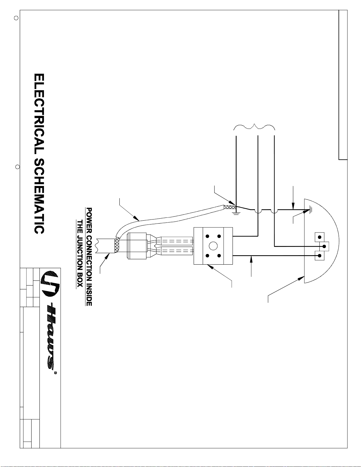
STEP 3: Connect electrical power supply conduit to input junction box using suitable conduit fitting into
3/4” NPT inlet. Install optional area light and indicator light, if desired. For MODEL
8317CTFP C1 D1 (120V): connect 120 volt AC line to 16 gauge shower wires as follows:
Black = 120 VAC, Red = 2
(Turn on power supply to complete installation. See Electrical Schematic Drawing, Sheet 4
of Installation Drawing). Power to be routed using rigid conduit and a seal fitting or Cla s s 1,
Division 1 rated armored cable and an appropriate gland fitting.
nd
Hot, Green = Ground.
OPERATING INSTRUCTIONS
Power to the 8317CTFP C1 D1 may be left on year round. The non-adjustable thermostat will shut off
heat cable when air temperature rises to 55º - 65º F (12º - 18º C). Heat cycle will repeat when air temperature drops to between 45º - 55º F (7º - 13ºC). Periodic check of water temperature from shower or
eye/face wash will confirm normal operating temperatures between 45º - 95ºF (7º - 35ºC).
This unit is heated by low power heat trace cable suitable for freeze protection but not suitable for providing a warm shower from a cold water supply. Moments after activating shower, water temperature will
drop to supply temperature.
ANSI recommends a comfortable shower temperature range of 60ºF (15ºC) to 100ºF (38ºC). For the protection of the user, we strongly recommend that some system be installed to provide tempered (warm)
water to this shower and eye/face wash. Heat trace cable used on this shower heats sl owly and may take
90 minutes to complete a full heat cycle.
No drain connection at bleed valve(s) is normally required. Valve(s) will remain closed unless power outage, high ambient temperature (with optional scald protection valve, only) or malfunction occurs (see
Troubleshooting).
NOTE: IF GROUND WATER IS BELOW 38ºF (3.3ºC) SIMPLY TESTING SHOWER MIGHT CAUSE
BLEED VALVE TO OPEN. ONCE OPENED, COLD GROUND WATER WILL KEEP BLEED VALVE
OPEN. SEE TROUBLESHOOTING GUIDE FOR PROCEDURE TO CLOSE BLEED VALVE ONCE
OPENED.
Periodic tests for proper function of shower and eye/face wash should be performed and recorded on inspection tags attached to unit or in separate maintenance logbook (preferred).
IMPORTANT SAFETY NOTICE
THE NATIONAL ELECTRICAL CODE REQUIRE GROUND-FAULT EQUIPMENT PROTECTION ON
EACH HEATING CABLE BRANCH CIRCUIT. TO REDUCE THE RISK OF FIRE CAUSED BY DAMAGE
OR IMPROPER INSTALLATION, CIRCUIT BREAKERS SUCH AS SQUARE D QO-EPD AND QOB-EPD
OR EQUIVALENT, WITH A 30mA TRIP LEVEL, SHOULD BE USED. PLEASE SUBSTITUTE THESE
BREAKERS WHEREVER REFERENCE IS MADE TO CONVENTIONAL BREAKERS IN THIS DOCUMENT. ALTERNATIVE DESIGNS PROVIDING COMPARABLE LEVELS OF GROUND-FAULT PROTECTION MAY ALSO BE ACCEPTABLE.
01/14 Model 8317CTFPC1D1 Page 3 of 10
Page 4

TROUBLESHOOTING
PROBLEM
1. Continuous flow from freeze bleed valve. 1.
2. Continuous flow from scald bleed valve.
(Optional valve).
3. Shower and eye/face wash water temperature below 40ºF or above 100ºF.
2.
REPAIR CHECKLIST
If bleed water temperature is above 45ºF (7ºC),
service bleed valve. For specific instruction regarding removal, maintenance and re-installment of this
model, contact Haws Technical Support at 1-800640-5612. If below 45ºF (7ºC), verify electric power
to unit, then check thermostat. See item 3 below.
Once opened, cold supply water, (45ºF (7ºC), will
keep freeze bleed valve open. To shut bleed valve,
it must be warmed above 45ºF (7ºC).
If bleed water temperature is below 90ºF (32ºC),
service bleed valve. For specific instruction regarding removal, maintenance and re-installment of this
model, contact Haws Technical Support at 1-800640-5612. Above 100ºF (38ºC) may be due to
direct sunlight or excess ambient temperature.
3. Shut off electric power. All electric connections
are made inside external junction box. Thermostat is mounted below junction box. Check
thermostat leads to terminal block for good connections. Check thermostat setting: open thermostat side cover and check that temperature
dial is set at 80ºF. Self-regulating heat trace cable will not overheat shower until air temperature rises above 85ºF (30ºC).
4. Removal of thermostat. 4. a. Disconnect the black, red, and green wires at
the thermostat (see page 8 of 8 for schematic).
b. Disconnect the black, red, and green wires at
the junction box.
c. Loosen set screw on kee-klamp and disassem-
ble the union between the junction box and
thermostat (see page 7 of 8 for clarification).
d. Remove thermostat from the shower assembly
(remember to de-pressurize the shower prior to
removal of thermostat and drain excess water
by activating eyewash). Hold coupling into which
thermostat is threaded firmly during removal in
order to keep it securely attached to shower assembly; otherwise a leak may occur under the
jacket.
5. Insufficient flow at shower and eye/face
wash.
5. Verify minimum 30 PSI (2 ATM), 28 gallon (106
liters per minute) available supply. Check for
blockage in lines.
6. Insufficient flow at eye/face washes only. 6. Probable clogging of flow control due to inadequate line flushing. Turn water supply off. Unscrew eye/face wash head and adapter to gain
access and clean flow control.
7. Insufficient water flow at the shower-
head, however, eye/face wash is sufficient.
7. Probable clogging of flow control inside showerhead. Unscrew showerhead off of elbow and
clean rubber flow control.
01/14 Model 8317CTFPC1D1 Page 4 of 10
Page 5

TROUBLESHOOTING (Continued)
PROBLEM
8. Shower and eye/face wash valve stem
leak.
9. Shower and eye/face wash valve leaks.
(Does not shut off completely).
For more information on Haws Products, please see our website: www.hawsco.com
© 2014 Haws
HAWS
®
®
Corporation – All Rights Reserved
and other trademarks used in these materials are the exclusive property of Haws Corporation.
REPAIR CHECKLIST
8. Remove shower arm or eye/face wash push
flag. Peel black trim strip from shower and separate housing halves. Peel back or remove insulation to gain access to valve. Remove “U”
bracket from valve stem and tighten valve stem
hex packing nut to stop leak. Reassemble
bracket, insulation, shower housing and valve
arm.
9. Disconnect power to unit. Disassemble as in
item 6. Check valve arm stop tang for damage.
Repair or replace valve assembly. Heat cable is
looped around valve and should be pulled away
from valve. Remove valve. Reverse above steps
to reassemble.
01/14 Model 8317CTFPC1D1 Page 5 of 10
Page 6
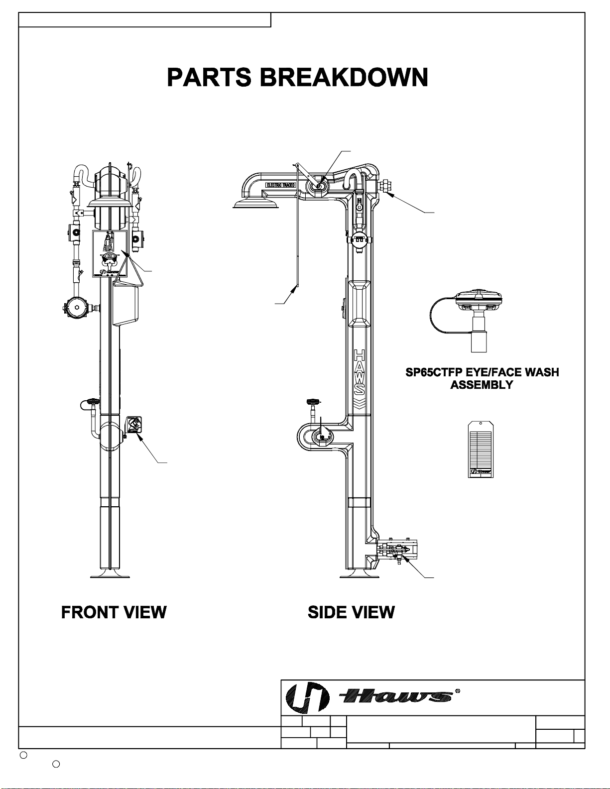
THIS DOCUMENT IS TRUE AND CORRECT AT TIME OF PUBLICATION. CONTINUED PRODUCT IMPROVEMENTS
MAKE SPECIFICATIONS AND MEASUREMENTS SUBJECT TO CHANGE WITHOUT NOTICE.
SHOWER VALVE ASSEMBL Y
SP829
SHOWER HEAD
SP178
SHOWER/EYEWASH
SIGN
PULL ROD
EYEWASH VA L VE
ASSEMBLY
1-1/4" UNION
SP200
SP170 TEST TAG
SP158B FREEZE
PROTECTION VALVE
(SEE PAGE S 8 & 9
FOR ADDITIONAL
COMPONENTS)
BYECN NO.
REVISED PER
4140
ECN:
SLS
4888
DATE
07/16/08
DATE
DRAWN
WHEN ORDERIN G PARTS PLEASE SPECIFY MO DEL NUMB ER.
C
2014
Haws Corporation - All Rights Reserved
HAWS and other trademarks used in these materials are the exclusive property of Haws Corporation.
R
APPROVED
HM
CHKD
MODEL(S)
1/9
SCALE:
8317CTFPC1D1
DRAWING TYPE: SIZE: A
PARTS BR EAKDO W N
1455 KLEPPE LANE
SPARKS, NEVADA 89431
(775) 359-4712 FAX (755) 359-74 24
E-MAIL: [email protected]
WEBSITE: WWW.HAWSCO.COM
PAGE
PART NUMBER
0002077032
DRAWING NO.
15362A00 9
SHEET OF
11
6 of 10
REV
Page 7
C
Haws Corporation - All Rights Reserved.
2014
MAKE SPECIFICATIONS AND MEASUREMENTS SUBJECT TO CHANGE WITHOUT NOTICE.
(NOTES CONTINUED ON SHEET 2 0F 3.)
HOLE SHOWN.
NOTE: PULL ROD AND HAN DLE NOT
MUST BE IN UP POSITION WHEN FULLY
CLOSED AND PULL ROD INSERTED IN
ASSEMBLED. ORIENTATION OF HANDLE
NOTES:
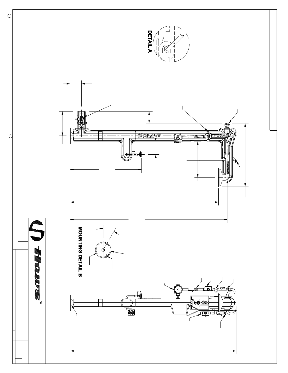
1. DIMENSIONS IN BRACKETS ARE IN MILLIMETERS.
2. UNLESS OTHERWISE SPECIFIED ALL TOLERANCES TO BE +/- 1/4 INCH.
3. TO COMPLY WITH ANSI Z358.1-2009 FOR EMERGENCY EYE/FACE WASH AND SHOWER EQUIPMENT:
- UNIT SHALL BE INSTALLED IN ACCORDANCE WITH MANUFACTURER'S INSTRUCTIONS AND ACCEPTABLE PLUMBING PRACTICES.
- EYE/FACE WASH SHALL BE POSITIONED WITH NOZZLES NOT LESS THEN 83.8 CM (33 IN.) AND NO GREATER THAN 114.3 CM (45 IN.)
FROM SURFACE ON WHICH USER STANDS AND 15.3 CM (6 IN.) MINIMUM FROM WALL OR NEAREST OBSTRUCTION.
- SHOWER SHALL BE POSITIONED SO THAT SHOWER HEAD IS NOT LESS THAN 208.3 CM (82 IN.) NOR MORE THAN 243.8 CM (96 IN.)
FROM SURFACE ON WHICH USER STANDS.
- SHOWER SPRAY PATTERN SHALL HAVE A MINIMUM DIAMETER OF 50.8 CM (20 IN.) AT 152.4 CM (60 IN.) ABOVE SURFACE ON WHICH
USER STANDS, AND CENTER OF SPRAY PATTERN SHALL BE LOCATED AT LEAST 40.6 CM (16 IN.) FROM ANY OBSTRUCTION.
THIS DOCUMENT IS TRUE AND CORRECT AT TIME OF PUBLICATION. CONTINUED PRODUCT IMPROVEMENTS
VIEW ROTATED 180°
SP158B FREEZE PROTECTION VALVE
(SEE NOTES ON SHEET 2 & 3 FOR
INSTALLATION INS TRUCTIONS.)
HAWS and other trademarks used in these materials are the exclusive property of Haws Corporation.
R
[355]
14"
[171]
BOTTOM SUPP LY UNIT
[171]
6 3/4
6 3/4
[1060]
41 3/4
[192]
7 1/2
CONNECTION
POWER
[529]
[2,172]
85 1/2
O&M MANUAL TO
CONVERT TO A
20 3/4
SUPPLY SHOWN . SEE
PROCEDURE IN THE
UNIO N (INLE T ) T O P
1-1/4" IPS SUPPLY
INSTALLATION
STEP 2 OF
SEE
DETAIL A
36 1/2
[929]
APPROVED:
DRAWN:
4140
SLS
REVISED PER
ECN:
DATE:
7/17/08
4888
DATE:
BY:ECN NO.
CHK'D.:
HM
SCALE:
MODEL(S)
1:1
DRAWING TYPE: SIZE: A
8317CTFPC1D1
INSTALLATION
0002077032.D
DRAWING NO.
PART NUMBER
SHEET OF
15363A00
14
[2,300]
90 1/2
30°
TRACED AND INSULATED
SUPPLY MUST BE HEAT
IMPORTANT
CONNECTIONS
KEE KLAMP
POWER
NO LIFT
[ø203]
ø8
[ø10]
THERMOSTAT
COUPLING
[ø228]
ø9
3X ø3/8
FLOOR LINE
(775) 359- 4712 FAX (755) 359-7424
E-MAIL: [email protected]
WEBSITE: WWW.HAWSCO.COM
SPARKS, NEVADA 89431
1455 KLEPPE LANE
DETAIL B
SEE MOUNTING
[2,431]
HEAT TRACE
TERMINATION
NO LIFT
95 3/4
REV
9
PAGE
7 of 10
Page 8
C
Haws Corporation - All Rights Reserv ed.
2014
HAWS and other trademarks used in these materials are the exclusive property of Haws Corporation.
MAKE SPECIFICATIONS AND MEASUR EM ENTS SUBJECT TO CHANGE WITHOUT NOTICE.
THIS DOCUMENT IS TRUE AND CORRECT AT TIME OF PUBLICATION. CONTINUED PRODUCT IMPROVEM ENTS
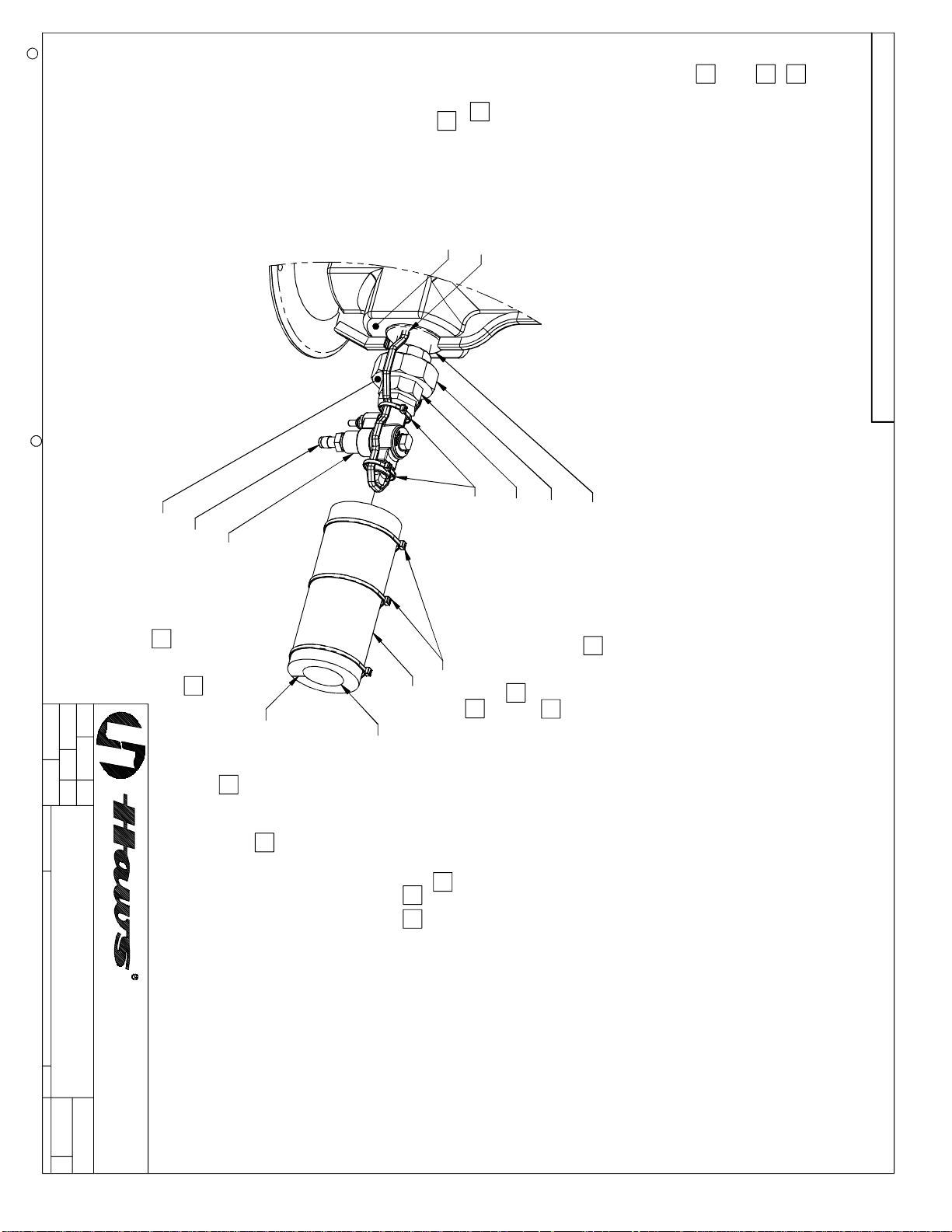
NOTES: (CONTINUED FROM SHEET 1 OF 4)
. FREEZE PROTECTION VALVE INSTALLATION INSTRUCTIONS:
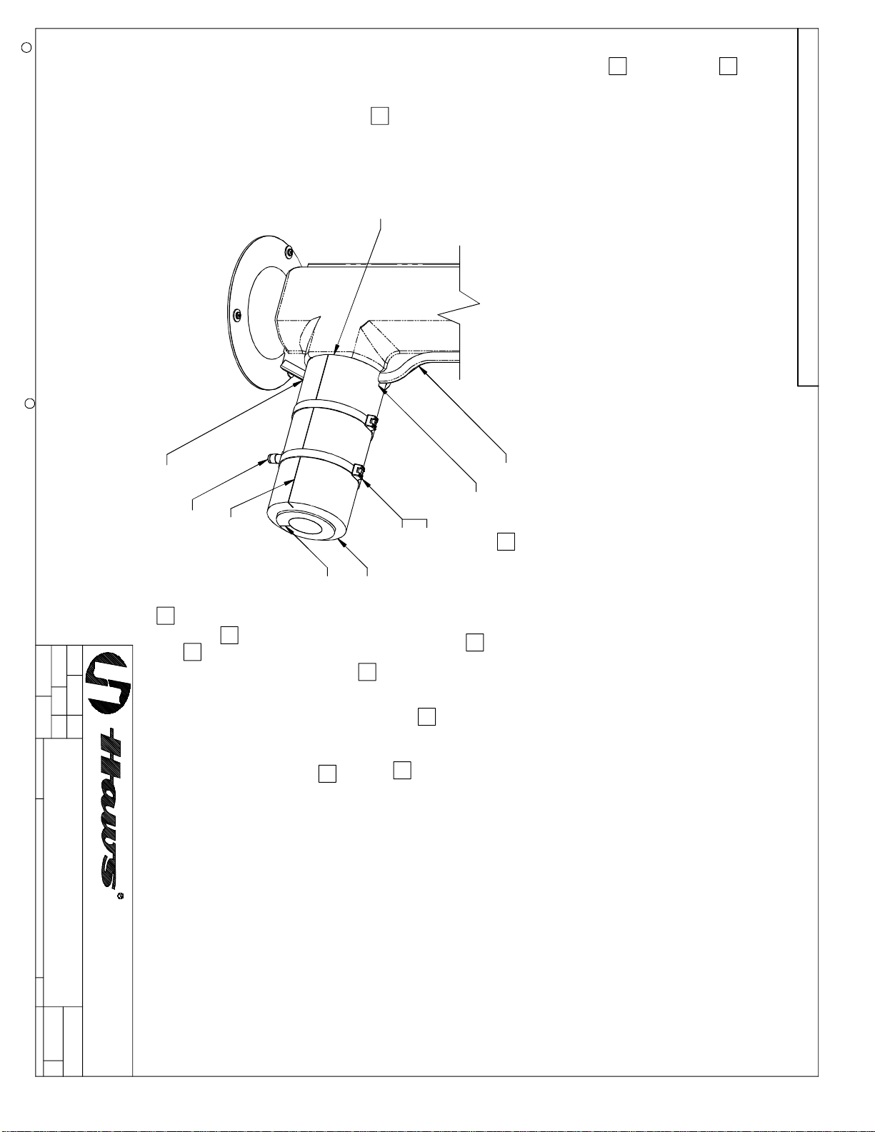
INSTALL VALVE SUB-ASSEMBLY INTO FEMALE SECTION OF UNION AND TIGHTEN WATER-TIGHT.
FORM HEAT TRACE CABLE AROUND VALVE AND PLUG, APPLY 2X CABLE-TIES TO HEAT TRACE CABLE, AS SHOWN, ENSURING
THAT HEAT TRACE CABLE IS PRESSED FIRMLY AGAINST SIDES OF VALVE (PUSH ANY LOOSE HEAT TRACE CABLE BACK INSIDE
JACKET THROUGH RUBBER GROMMET). TRIM EXCESS CABLE-TIE STRAPPING.
SLIDE INNER TUBE W/ PLUGGED END OVER VALVE WITH ADHESIVE SEAM FACING BOTTOM AND NON-PLUGGED END OF TUBE
BUTTED UP AGAINST UNION SURFACE. REMOVE 2X ADHESIVE TAPE FROM SEAM AND SQUEEZE ADHESIVE SEAMS TOGETHER
AROUND VALVE. APPLY 2X CABLE-TIES TO TUBE, IN APPROXIMATE LOCATIONS SHOWN. TRIM EXCESS CABLE-TIE STRAPPING.
REFERENCE ONLY. VALVE CAN BE INSTALLED AT TOP OR BOTTOM.
(NOTES CONTINUED ON SHEET 3 OF 4)
C
B
4
A
SP158B VALVE SHOWN CONNECTED TO BOTTOM UNION FOR
E
HEAT TRACE CABLEB
JACKET SURFACE
(SEE SHEET 3.)
R
CABLE-TIE, 15" / PN 0005972499 B
UNION SURFACE
MALE SECTION OF UNION
(PART OF VALVE SUB- ASSY)
FEMALE SECTION OF UNION
(PART OF SHOWER UNIT)
RUBBER GROMMET
BARBED CONNECTOR
VALVE, FREEZE (NO UNION) SP158B
C
C
APPROVED:
DRAWN:
4632
VWC
REVISED PER
ECN:
DATE:
12/2/12
4888
DATE:
CHK'D.:
BY:ECN NO.
HM
SCALE:
MODEL(S)
NA
DRAWING TYPE: SIZE: A
ADHESIVE SEAM
PLUGGED END
A
C
CABLE-TIE, 15" / PN 0005972499
INNER TUBE W/ PLUGGED END
A
C
B
A
C
8317CTFPC1D1
D
INSTALLATION
DRAWING NO.
SHEET OF
0002077032
15363A 9
24
REV
(775) 359-4712 FAX (755) 359-7424
E-MAIL: [email protected]
WEBSITE: WWW.HAWSCO. C OM
SPARKS, NEVADA 89431
1455 KLEPPE LANE
PART NUMBER
PAGE
8 OF 10
Page 9
C
Haws Corporation - All Rights Reserv ed.
2014
HAWS and other trademarks used in these materials are the exclusive property of Haws Corporation.
R
REFERENCE ONLY. VALVE CAN BE INSTALLED AT TOP OR BOTTOM.
SP158B VALVE SHOWN CONNECTED TO BOTTOM UNION FOR
MAKE SPECIFICATIONS AND MEASUR EM ENTS SUBJECT TO CHANGE WITHOUT NOTICE.
THIS DOCUMENT IS TRUE AND CORRECT AT TIME OF PUBLICATION. CONTINUED PRODUCT IM PROVEMENTS
NOTES: (CONTINUED FROM SHEET 2 OF 4)
FREEZE PROTECTION VALVE INSTALLATION INSTRUCTIONS (CONTINUED):
WRAP OUTER TUBE OVER INNER TUBE ENCAPSULATED VALVE WITH ADHESIVE SEAM ORIENTED PERPENDICULAR
TO SEAM OF INNER TUBE. PUSH OUTER TUBE UP AGAINST JACKET SURFACE. WHEN TUBE IS MOUNTED FIRMLY
AGAINST JACKET SURFACE, SQUEEZE TUBE AT BARBED CONNECTOR SUCH THAT BARBED NIPPLE PUSHES
THROUGH OUTER TUBE WALL. (PUSHING CONNECTOR THROUGH WALL WILL EXTRUDE A CYLINDRICAL PLUG OF
TUBING TO BREAK FREE. DISCARD PLUG.) PUSH TUBE DOWN EVEN FURTHER SO THAT HOLE IN TUBE STRETCHES
AROUND HEXAGONAL BOSS OF CONNECTOR. SQUEEZE OUTER TUBE TIGHT UNTIL ADHESIVE SEAMS ARE CLOSE
ENOUGH TO SEAL. REMOVE PROTECTIVE TAPE AND SEAL SEAMS.
TO ENSURE PROPER INSULATION OF UNION; THERE MUST BE NO SPACE BETWEEN OUTER TUBE AND JACKET
SURFACE (SEE SHEET 2 FOR SURFACE CALLOUT). THEREFORE, SLICE TWO PLACES, TOP SIDE AND BOTTOM SIDE,
COMPLETELY THROUGH OUTER TUBE TO A LENGTH EQU AL TO DEPTH O F TRIM SEA L. FORCE SLICED TUBE
AROUND TRIM SEAL AND PUSH TUBE TIGHTLY AGAINST JACKET, AS SHOWN. APPLY 2X CABLE-TIE HEAD, AND 2X
CABLE-TIE STRAP, TO TUBE, IN APPROXIMATE LOCATIONS SHOWN. TRIM EXCESS STRAPPING.
E
5.
D
E
INTERSECTION
JACKET/TUBE
(BOTTOM SIDE)
SLICED TUBE SECTION
(TOP SIDE)
BARBED CONNECTOR
PERPENDICULAR
ADHESIVE SEAM
INNER TUBE INSULATION SEAM
HEAD, 2-PC CABLE-TIE / PN 0002850165
STRAP, 2-PC CABLE-TIE, 20" L
OUTER TUBE
TRIM SEAL E
SLICED TUBE SECTION
E
D
APPROVED:
DRAWN:
4632
VWC
REVISED PER
ECN:
DATE:
12/2/12
4888
DATE:
CHK'D.:
BY:ECN NO.
HM
SCALE:
MODEL(S)
NA
DRAWING TYPE: SIZE: A
D
D
D
D
D
E
8317CTFPC1D1
INSTALLATION
PART NUMBER
DRAWING NO.
SHEET OF
0002077032
15363A 9
34
REV
WEBSITE: WWW.HAWSCO. C OM
(775) 359-4712 FAX (755) 359-7424
E-MAIL: [email protected]
SPARKS, NEVADA 89431
1455 KLEPPE LANE
PAGE
9 OF 10
Page 10
C
Haws Corporation - All Rights Reserved.
2014
MAKE SPECIFICATIONS AND MEASUREMENTS SUBJECT TO CHANGE WITHOUT NOTICE.
THIS DOCUMENT IS TRUE AND CORRECT AT TIME OF PUBLICATION. CONTINUED PRODUCT IMPROVEMENTS
CUSTOMER TO SUPPLY
120VAC SERVICE
HAWS and other trademarks used in these materials are the exclusive property of Haws Corporation.
TERM. RING (3X)
GREEN
GROUND
BLACK
WHITE
GREEN/YELLOW
RING
GREEN
TERM.
NO
COM
NC
R
APPROVED:
DRAWN:
4140
SLS
REVISE D PER
ECN:
DATE:
7/17/08
4888
DATE:
CHK'D.:
BY:ECN NO.
HM
SCALE:
MODEL(S)
HEAT TRACE CABLE
RED (30")
TERMINAL BLOCK
THERMOSTAT
1:1
DRAWING TYPE: SIZE: A
8317CTFPC1D1
INSTALLATION
0002077032.D
PART NUMBER
DRAWING NO.
SHEET OF
15363A00
44
REV
9
(775) 359-4712 FAX (755) 359- 7424
E-MAIL: [email protected]
WEBSITE: WWW.HAWSCO.COM
SPARKS, NEVADA 89431
1455 KLEPPE LANE
PAGE
10 of 10
 Loading...