

Page 1

OPERATING MANUAL
Hausted® Horizon® Series
Multi-Purpose Stretchers – Electric Powered
Models: 4E1 & 4E2 (120 VAC), 4D2 (230 VAC)
(08/30/06) 069389
Page 2

A WORD FROM STERIS CORPORATION
Indications for Use
This manual contains important information on proper use and maintenance
of the Hausted® Horizon® Series Multi-Purpose Stretchers – Electric Powered.
All personnel involved in the use and maintenance of this equipment mustAll personnel involved in the use and maintenance of this equipment must
All personnel involved in the use and maintenance of this equipment must
All personnel involved in the use and maintenance of this equipment mustAll personnel involved in the use and maintenance of this equipment must
carefully review and comply with the warnings, cautions and instructionscarefully review and comply with the warnings, cautions and instructions
carefully review and comply with the warnings, cautions and instructions
carefully review and comply with the warnings, cautions and instructionscarefully review and comply with the warnings, cautions and instructions
contained in this manual. contained in this manual.
contained in this manual. These instructions are important to protect the
contained in this manual. contained in this manual.
health and safety of personnel operating a Hausted Horizon Series Electric
Powered Multi-Purpose Stretcher and should be retained in a conveniently
accessible area for quick reference.
Complete instructions for uncrating and connecting utilities, as well as
equipment drawings, have been furnished. If missing, contact STERIS for
replacement copies, giving the serial number and model numbers of the unit.
STERIS carries a complete line of accessories for use with these stretchers.
A STERIS representative will gladly review these with you.
The Hausted Horizon Series Multi-Purpose Stretchers – Electric Powered are
intended for use in patient treatment, transport or recovery.
Service Information
Advisory
A thorough preventive maintenance program is essential to safe and proper
unit operation. This manual contains maintenance schedules and procedures
which should be followed for satisfactory equipment performance.
You are encouraged to contact STERIS concerning our comprehensive
Annual Maintenance Agreements. Under the terms of these agreements,
preventive maintenance, adjustments, and replacement of worn parts are
done on a scheduled basis to assure equipment performance at peak
capability and to help avoid untimely or costly interruptions. STERIS maintains
a global staff of well equipped, factory-trained technicians to provide this
service, as well as expert repair services. Please contact your STERIS
representative for details.
A listing of the safety precautions to be observed when operating and
servicing this equipment can be found in
operate or service the equipment until you have become familiar with this
information.
Any alteration of this equipment not authorized or performed by STERIS
Engineering Service which could affect its operation will void the warranty,
could adversely affect sterilization efficacy, could violate national, state, and
local regulations, and could jeopardize your insurance coverage.
S
ECTION
1
of this manual. Do not
©2006, STERIS Corporation. All rights reserved. Printed in U.S.A.
Table of Contents Operator Manual 069389
i
Page 3

EC Authorized Representative
STERIS Limited
STERIS House
Jays Close
Viables
Basingstoke
Hampshire
RG22 4AX
UNITED KINGDOM
Manufactured by:
STERIS Corporation
2720 Gunter Park East
Montgomery, AL 36109 • USA
www.steris.com
TEL: 334 277 6660
FAX: 334 271 5450
Class 1 Equipment
Type B Equipment
Equipment not suitable for use
in the presence of a flammable
anesthetic mixture with air or
oxygen or nitrous oxide.
IPX4 (Splash-proof Equipment)
Not suitable for continuous opera-
tion (Duty Cycle: 10% six minutes
in one hour)
STERIS Corporation,
Montgomery, Alabama is an
ISO 13485 certified facility.
The base language of this document is
ENGLISH. Any translations must be
made from the base language docu-
ment.
ii
069389 Operator Manual Table of Contents
Page 4

TABLE OF CONTENTS
Section Title Page
1 LISTING OF WARNINGS AND CAUTIONS ....................................... 1-1
2 UNPACKING INSTRUCTIONS ......................................................... 2-1
3 OPERATING INSTRUCTIONS .......................................................... 3-1
3.1 Stretcher Specifications ............................................................................................... 3-1
3.2 Features, Warnings and Proper Operation ................................................................... 3-3
3.3 Braking and Steering Operation ................................................................................... 3-5
3.3.1 Applying the Brakes ............................................................................................. 3-5
3.3.2 Releasing the Brakes............................................................................................ 3-5
3.3.3 Applying the Steering Lock/Fifth Wheel ................................................................ 3-5
3.3.4 Releasing the Steering Lock/Fifth Wheel .............................................................. 3-5
3.4 Litter Top Height Adjustment (4E1 Models Only) ......................................................... 3-6
3.4.1 Height Adjustment ................................................................................................ 3-6
3.4.2 Lowering Litter Top ................................................................................................ 3-6
3.4.3 Trendelenburg Adjustment .................................................................................... 3-6
3.4.4 Reverse Trendelenburg Adjustment ...................................................................... 3-7
3.5 Electric Control Locations ............................................................................................. 3-7
3.5.1 Nurses Control Panel ............................................................................................ 3-7
3.5.2 Patient Pendant ..................................................................................................... 3-7
3.5.3 Plug Locations ...................................................................................................... 3-7
3.5.4 Emergency Electric Backrest Overide .................................................................. 3-8
3.5.5 Low Battery Light (L.E.D.) ..................................................................................... 3-8
3.6 Litter Top Adjustment ................................................................................................... 3-8
3.6.1 Height Adjustment (4E2 & 4D2 Models Only) ....................................................... 3-8
3.6.2 Fowler Adjustment ................................................................................................ 3-9
3.6.3 Quick Drop Activation (Fowler Backrest) .............................................................. 3-9
3.6.4 Knee Flex Adjustment .......................................................................................... 3-9
3.6.5 Trendelenburg Adjustment (4E2 & 4D2 Models only) ........................................... 3-10
3.7 Airglide Rail Operation ................................................................................................3-10
3.7.1. Raising the Rail ................................................................................................... 3-10
3.7.2 Lowering the Rail.................................................................................................. 3-10
3.8 Retracto Rail Operation ............................................................................................... 3-11
3.8.1 Raising the Rail .................................................................................................... 3-11
3.8.2 Half Height ........................................................................................................... 3-11
3.8.3 Lowering the Rail.................................................................................................. 3-11
3.9 Push Handle Operation (Optional Accessory) .............................................................3-12
3.9.1 Raising the Push Handles .................................................................................... 3-12
3.9.2 Lowering the Push Handles ................................................................................. 3-12
3.10 Permanently Mounted IV Rod Operation ................................................................... 3-12
3.10.1 Putting I.V. Rod in Up Position ........................................................................... 3-12
3.10.2 Extending I.V. Rod ............................................................................................. 3-13
3.10.3 Retracting I.V. Rod .............................................................................................3-13
4 TROUBLE SHOOTING GUIDE .......................................................... 4-1
4.1 Electric Powered Stretchers ......................................................................................... 4-1
4.2 Battery Replacement Instructions ................................................................................ 4-2
Table of Contents Operator Manual 069389
iii
Page 5

Section Title Page
5 RECOMMENDED PREVENTIVE MAINTENANCE............................ 5-1
5.1 Recommended Cleaning Instructions .......................................................................... 5-1
6 OPTIONAL ACCESSORIES.............................................................. 6-1
7 RECOMMENDED REPLACEMENT PARTS ...................................... 7-1
iv
069389 Operator Manual Table of Contents
Page 6
LISTING OF WARNINGS AND CAUTIONS
1
The following
Stretchers. WARNING indicates the potential for personal injury and CAUTION indicates the potential for damage to
equipment. For emphasis, certain
Safety Precautions
Strictly following these
customer avoid improper maintenance methods which may damage the unit or render it unsafe. It is importantto
understand that these
policies and procedures to enhance and compliment these
Safety Precautions
before operating or servicing the unit.
Safety Precautions
Safety Precautions
must be observed when operating or servicing this Hausted® Horizon® Multi-Purpose
Safety Precautions
enhances your ability to safely and effectively utilize the unit and helpsthe
are not exhaustive; customers are encouraged to develop their ownsafety
are repeated throughout the manual. It is important toreview ALL
Safety Precautions.
WARNING–LACERATION HAZARD:
When cutting bands always use a tool specifically designed for that purpose. This will help to avoid personal
injuries frequently incurred when bands are cut and tension released.
WARNINGS – PERSONAL INJURY:
Do not sit on end – tipping may occur.
Be sure I.V. rod is inserted completely into socket up to the arrow before applying load.
To reduce the risk of electric shock, do not remove the cover. Unit is to be service by qualified personnel only.
See
S
ECTION
3
for the Warnings below:
WARNINGS – CAUTIONS AND PROPER OPERATION:
The stretchers have a warning label located at the head end stating: Maximum patient weight 226 Kilograms (500
lbs.) This is true for all models except the 4E2DPA or 4D2DPA which states: Maximum patient weight
283 Kilograms (625 lbs.).
Patient entry, egress and transfer should always be done with the brakes locked.
The brakes should always be on and patient side rails up when the patient is not in transport.
The patient pendant has a warning label on it stating: Clip Pendant to rail when not in use - Keep cord clear of
moving parts.
It is important to remember that all electric stretchers are equipped with a built in battery back- up system but:
it is recommended that the unit remain plugged in wall receptacle during normal use. The battery backup is
recommended for transport and emergency only.
The Fowler backrest quick drop handle is intended to be used during emergency situations only.
Be sure rail is locked before leaving patient.
The lock out controls on the nurse control box controls both the pendant and the control panel.
To turn electric controls on, plug into wall receptacle. To turn off, remove plug from wall receptacle. The electric
powered stretcher do no have a separate on/off switch.
Continued. . . .
Listing of Warnings and Cautions Operator Manual 069389
1-1
Page 7

The stretcher has a warning label located on the control box cover stating: To reduce the risk of electrical shock
do not remove the cover. Service by qualified personnel only.
Always disconnect the power source whenever servicing any electric powered stretcher.
Do not use a sharp instrument to remove fuse, as it may scratch the circuit board.
The batteries are wired in series, failure to install or rewire the same way may cause the batteries to explode.
WARNING – CAUTIONS AND PROPER OPERATION (Continued):
Floors must be smooth and level to maintain optimum fifth wheel steering. Fifth wheel steering functions can be
influenced by floor irregularities (bumps or dips) greater than 1/2" (13 mm) across the span of the stretcher.
1-2
069389 Operator Manual Listing of Warnings and Cautions
Page 8

UNPACKING INSTRUCTIONS
IMPORTANT: Report any shipping damage immediately! Inform shipper of
any damages, and leave carton intact. Leave the stretcher in receiving area until
inspection is complete.
Your Hausted® Horizon® Multi-Purpose Stretcher has been carefully packaged
at our manufacturing plant to ensure safe shipment to you medical facility. There
are several procedures you must follow to put your new stretcher into service.
These procedures only take a few minutes to complete and are required to
ensure proper operation of the stretcher.
2
WARNING – LACERATION
HAZARD: When cutting
bands always use a tool specifically designed for that
purpose. This will help to
avoid personal injuries frequently incurred when
bands are cut and tension
released.
Step 1 – Cut the two bands around the shipping carton.
Step 2 – Remove the top half of the carton and cut one side of the bottom half.
Step 3 – Remove the stretcher from the carton. Cut the bands from around the
stretcher.
Step 4 – Check to see if all features of the stretcher work properly.
NOTE: You must first plug the unit into a wall socket to check any
electric features, as the battery has not been charged (see Step 6).
If all features work properly, go to step 5. If any of the features of the
stretcher do not work properly, call STERIS for service.
Step 5 – Clean the stretcher using a mild detergent to remove any dirt
accumulated during shipment.
Step 6 – Plug the unit into a wall socket to charge for approximately 8 hours
to charge the battery backup.
Step 7 – Place the unit into service.
2-1
Unpacking Instructions Operator Manual 069389
Page 9

OPERATING INSTRUCTIONS
3.1 Stretcher
Specifications
WARNING –PERSONAL
INJURY: The stretchers
have a warning label located
at the head end stating:
maximum patient weight
226 Kilograms (500 lbs.).
This is true for all models
except for the 4E2DPA or
4D2DPA which states: Maximum patient weight 283
Kilograms (625 lbs.).
NOTE: All dimensions are specified
in inches.
All dimension are ±.375 inches.
3
STERIS reserves the right to change
specifications without notice.
Stretcher weight: 315 lbs.
KNEE FLEX
Electrical Specifications
(Applies only to 4E1 & 4E2 Models)
Product Classifiation: 1
Input Voltage: 120V ~, +/-5%, 60Hz
Amperage: Max. 3.5A
Duty cycle: 10% 6 Min in 1 Hr.
IP Rating: IPX 4
Grounding Protection: Type B
KNEE FLEX
90° MAx
DPA Models Specifications Shown
Electrical Specifications
(Applies only to 4D2 Model)
Product Classifiation: 1
Input Voltage: 230V ~, +/-10%, 50Hz
Amperage: Max. 1.9A
Duty cycle: 10% 6 Min in 1 Hr.
IP Rating: IPX 4
Grounding Protection: Type B
3-1
Operating Instructions Operator Manual 069389
Page 10
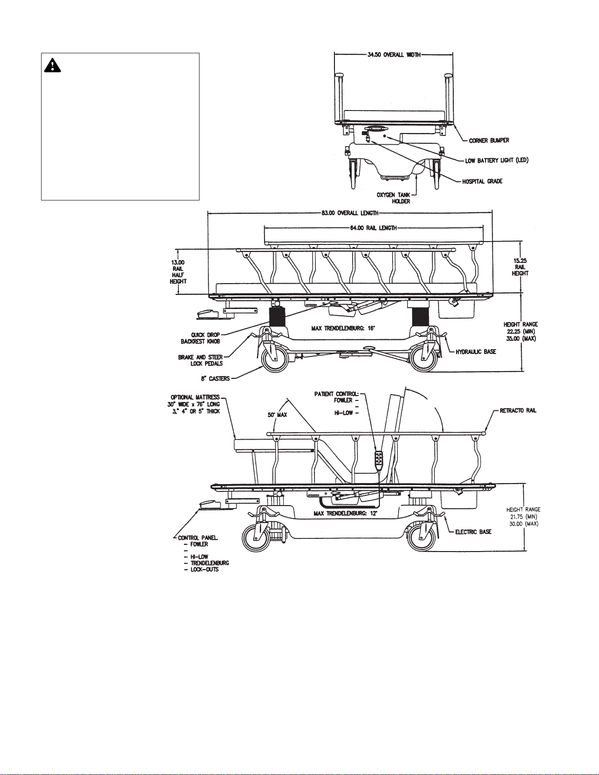
WARNING–PERSONAL
INJURY: The stretchers
have a warning label located
at the head end stating:
maximum patient weight
226 Kilograms (500 lbs.).
This is true for all models
except for the 4E2DPA or
4D2DPA which state: Maximum patient weight 283
Kilograms (625 lbs.).
Model 4E1HMC (hydraulic
base) maximum Patient
weight: 500 lbs.
Model 4E2HMC (electric
base) maximum Patient
weight: 500 lbs.
NOTE: All dimensions are specified
in inches.
All dimension are ±.375 inches.
STERIS reserves the right to change
specifications without notice.
Stretcher weight: 315 lbs.
KNEE FLEX
Electrical Specifications
(Applies only to 4E1 & 4E2 Models)
Product Classifiation: 1
Input Voltage: 120V ~, +/-5%, 60Hz
Amperage: Max. 3.5A
Duty cycle: 10% 6 Min in 1 Hr.
IP Rating: IPX 4
Grounding Protection: Type B
KNEE FLEX
90° MAx
HMC Models Specifications Shown
Electrical Specifications
(Applies only to 4D2 Model)
Product Classifiation: 1
Input Voltage: 230V ~, +/-10%, 50Hz
Amperage: Max. 1.9A
Duty cycle: 10% 6 Min in 1 Hr.
IP Rating: IPX 4
Grounding Protection: Type B
3-2
069389 Operator Manual Operating Instructions
Page 11

3.2 Features,
Warnings and Proper
Operation
WARNINGS –CAUTIONS AND PROPER
OPERATION:
A– The stretchers have a warning label located at
the head end stating: maximum patient weight
226 Kilograms (500 lbs.). This is true for all
models except the 4E2DPAor 4D2DPA which
states: Maximum patient weight 283 Kilograms
(625 lbs.).
B– Patient entery, egress and transfer should
always be done with the brakes locked.
C– The brakes should always be on and patient
side rails up when
the patient is not in trasnport.
D– The patient pendant has a warning label on it
stating: Clip Pendant to rail when not in use –
Keep cord clear of moving parts.
E –It is important to remember that all electric
stretchers are equipped with a built in battery
backup system but: it is recommended that
the unit remain plugged in wall receptacle
during normal use. The battery backup is
recommended for transport and emergency
only.
I– Floors must be smooth and level to maintain
optimum fifth wheel steering. Fifth wheel steering functions can be influenced by floor irregularities (bumps or dips) greater than 1/2"
(13 mm) across the span of the stretcher.
WARNINGS RELATED TO SERVICE & REPAIR:
J– To turn electric controls on, plug into wall
receptacle, to turn off, remove plug from wall
receptacle, the electric powered stretcher do
no have a separate on/off switch.
K– The stretcher has a warning label located on
the control box cover stating: To reduce the
risk of electrical shock don not remove the
cover. Service by qualified personnel only.
L– Always disconnect the power source when-
ever servicing any electric powered stretcher.
M–Do not use a sharp instrument to remove fuse,
as it may scratch the circuit board.
N– The batteries are wired in series, failure to
install or rewire the same way may cause the
batteries to explode.
F– The Fowler backrest quick drop handle is
intended to be used during emergency situa-
tions only.
G–Be sure rail is locked before leaving patient.
H– The lock out controls on the nurse control box
controls both the pendant and the control
panel.
Important Note: The picture shown is of the “DPA” models, all cautions and warnings also apply to the “HMC” models.
3-3
Operating Instructions Operator Manual 069389
Page 12
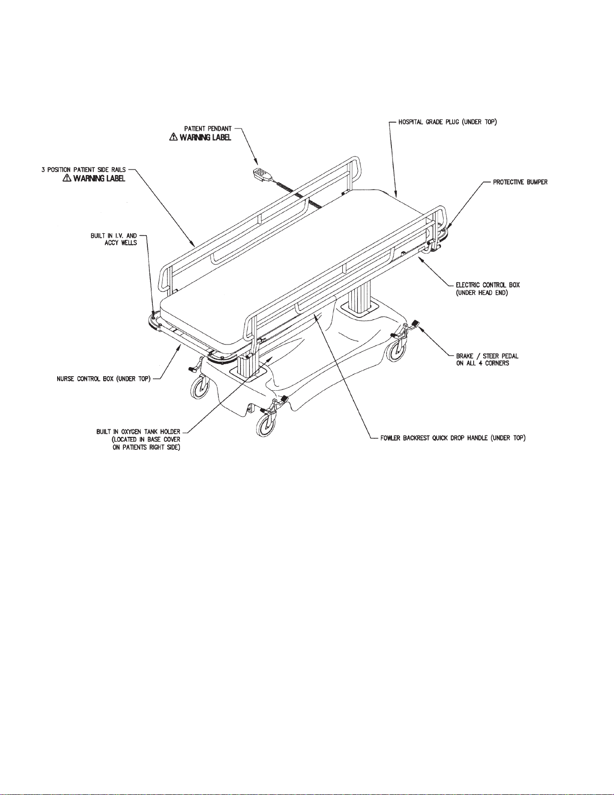
See Warnings C & G
See Warning H
See Warnings E & J
See Warnings D & H
See Warnings J thru N
See Warnings B & C
See Warning F
3-4
069389 Operator Manual Operating Instructions
Page 13
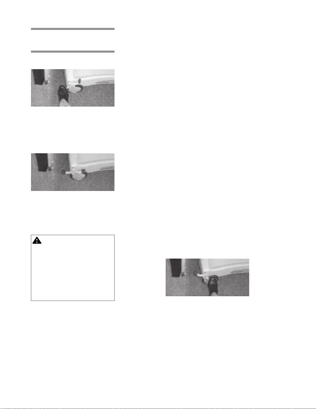
3.3 Braking and
Steering Operation
3.3.1 Applying the Brakes
Figure 3-1.
3.3.2 Releasing the Brakes
Figure 3-2.
The four wheel central braking system is activated by depressing the red pedal
at any of the four corners of the unit (Figure 3-1). To fully engage the brakes, the
pedal should be pressed to approximately 45º. All four caster wheels should be
locked from swiveling and rotating.
Depress the green pedal at any of the four corners of the unit, until the pedal is
in a horizontal position (Figure 3-2). All four wheels should rotate and swivel
freely.
NOTE: Brakes should always be activated when unit is not in transport.
3.3.3 Applying the
Steering Lock/Fifth Wheel
WARNING – PROPER OPERATION: Floors must be
smooth and level to maintain optimum fifth wheel
steering. Fifth wheel steering functions can be influenced by floor irregularities
(bumps or dips) greater than
1/2" (13 mm) across the span
of the stretcher.
3.3.4 Releasing the
Steering Lock/Fifth Wheel
From any corner of the stretcher, depress the green pedal downward into locked
position (Figure 3-3). Push the stretcher forward. Either one caster at the foot end
will lock into a non-swivel mode, or the optional fifth wheel will lower and apply
pressure to the floor. This allows straight steering by the attendant.
Figure 3-3.
Depress the red pedal at any of the four corners of the unit, until the pedal is in
a horizontal position (Figure 3-2). All four wheels should rotate and swivel freely,
and/or the optional fifth wheel will retract.
3-5
Operating Instructions Operator Manual 069389
Page 14
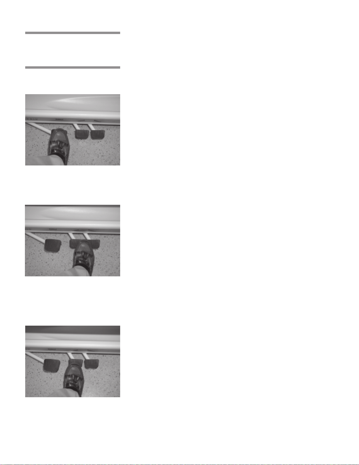
3.4 Litter Top Height
Adjustment
(4E1 Models Only)
3.4.1 Height Adjustment
Figure 3-4
3.4.2 Lowering Litter Top
Press the pump pedal to the floor (Figure 3-4), then release. Repeat this
process until desired height is obtained. Use smooth strokes on the pedal to
ensure patient comfort.
Press down on the two release pedals at the same time (Figure 3-5) until
desired height is obtained.
NOTE: Do not stand on release pedals.
Figure 3-5
3.4.3 Trendelenburg Adjustment
Place the unit at maximum height, see
release pedal nearest the head end (Figure 3-6) until desired position is
obtained. Then remove pressure.
Height Adjustment
. Press down on the
Figure 3-6
3-6
069389 Operator Manual Operating Instructions
Page 15
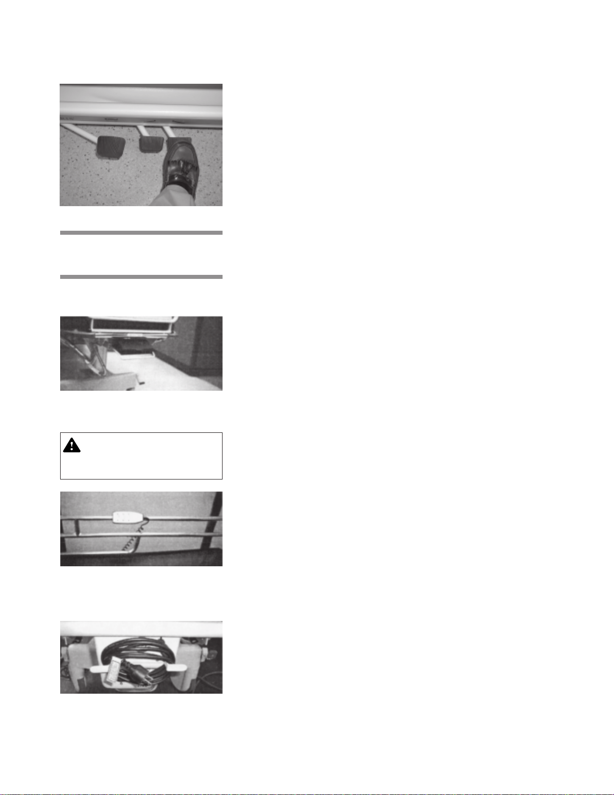
3.4.4 Reverse
Trendelenburg Adjustment
Figure 3-7
3.5 Electric Control Locations
Place the unit at maximum height, see
release pedal nearest the foot end (Figure 3-7) until desired position is
obtained. Then remove pressure.
Height Adjustment
. Press down on the
3.5.1 Nurses Control Panel
Figure 3-8.
3.5.2 Patient Pendant
CAUTION: Clip pendant to
rail when not in use. Keep
cord clear of moving parts.
Figure 3-9.
To access the nurses control panel, pull out on the handle located at the foot end
of the unit, under the top (Figure 3-8).
The patient Pendant has an adjustable location and may be located on either
side of the rail (Figure 3-9).
3.5.3 Plug Locations The hospital grade plug is located under the head end of top section
(Figure 3-10). Unwrap cord from bracket and plug into the nearest wall
receptacle.
Important: It is recommended that unit remain plugged in wall receptacle during
normal use. Battery back-up is recommended for transport and emergency only.
Figure 3-10.
3-7
Operating Instructions Operator Manual 069389
Page 16
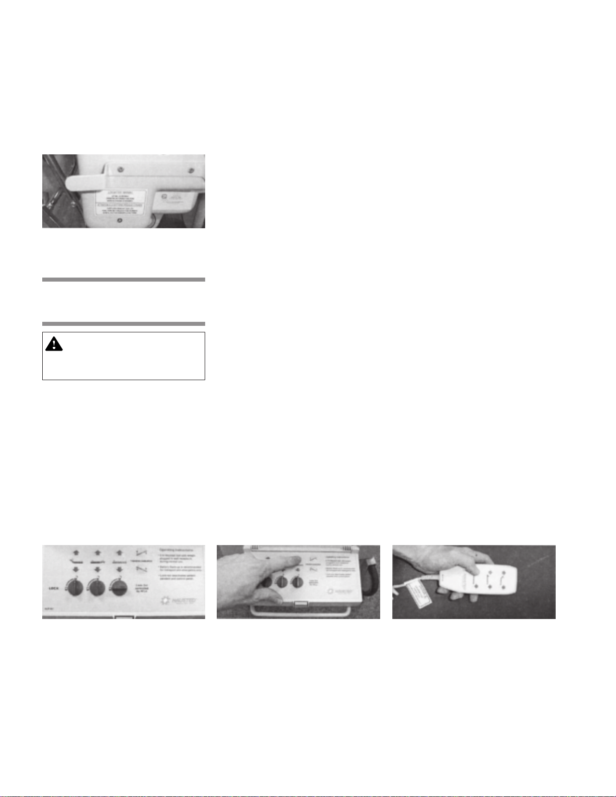
3.5.4 Emergency Electric Backrest Override
The unit is equipped with a Fowler backrest quick drop handle located under the
litter top at stretcher mid section. (See the stretcher specification page). This
option is only to be used in an emergency situation. The label states:
Drop Backrest Pull Handle to Activate
.
Emergency
3.5.5 Low Battery Light (L.E.D.)
Figure 3-11.
3.6 Litter Top Adjustment
CAUTION: The lock-out controls both the pendant and
the control panel.
3.6.1 Height Adjustment
(4E2 & 4D2 Models Only)
The stretchers are equipped with a low battery indictor light, located on
the controller cover under the head end of the stretcher (Figure 3-11).
When a button on the pendant is pressed, and the L.E.D. light comes on, it
indicates that the backup batteries require charging. Plug the unit into a wall
receptacle.
Lockout –
control panel, clockwise approximately 90º (Figure 3-12).
under the third row of buttons, counter-clockwise approximately 90º.
Unlocking
: Turn the knob located under the third row of buttons on the
Locking
: Turn the knob
Figure 3-12.
NOTE: This lockout knob also controls the trendelenburg functions.
Nurse: Press either of the up or down arrows located on the third row of buttons
on the control panel (Figure 3-13). Hold in the button until the desired height is
achieved.
Patient: Press either of the up or down arrows located on the third row of buttons
on the patient pendant (Figure 3-14). Hold the button in until desired height is
achieved.
Figure 3-13.
Figure 3-14.
3-8
069389 Operator Manual Operating Instructions
Page 17
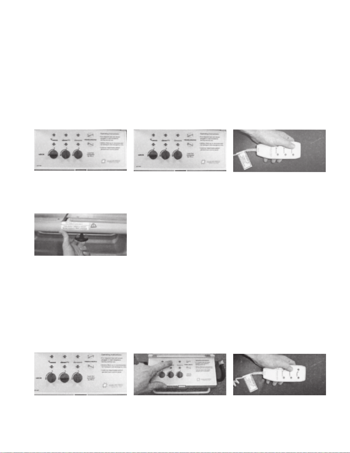
3.6.2 Fowler Adjustment
Lockout –
control panel, clockwise approximately 90º (Figure 3-15).
under the first row of buttons, counter-clockwise approximately 90º.
Nurse: Press either of the up or down arrows located on the first row of buttons
on the control panel (Figure 3-16). Hold in the button until desired incline is
achieved.
NOTE: This unit is equipped with a Fowler backrest quick drop handle located
on either side of the stretcher near the foot section (see stretcher specification
page). This option is only to be used during an emergency situation.
Patient: Press either of the up or down arrows located on the first row of buttons
on the patient pendant (Figure 3-17). Hold in the button until desired incline is
achieved.
Unlocking
: Turn the knob located under the first row of buttons on the
Locking
: Turn the knob
Figure 3-15. Figure 3-16.
3.6.3 Quick Drop
Activation (Fowler
Backrest)
The stretcher is equipped with manual override function for the Fowler backrest.
This option should only be used in an emergency situation. To activate the quick
drop, pull out on the red “T” handle (Figure 3-18) located under the litter top on
either side of the patient, near the middle of the unit.
Figure 3-18.
3.6.4 Knee Flex Adjustment
Lockout –
control panel, clockwise approximately 90º (Figure 3-19).
Turn the knob under the second row of buttons, counter-clockwise approximately 90º.
Nurse: Press either of the up or down arrows located on the second row of
buttons on the control panel (Figure 3-20). Hold in the button until desired
height is achieved.
Patient: Press either of the up or down arrows located on the first row of
buttons on the patient pendant (Figure 3-21). Hold in the button until desired
height is achieved.
Unlocking
: Turn the knob located under the second row of buttons on
Figure 3-17.
Locking
:
Figure 3-19. Figure 3-20. Figure 3-21.
3-9
Operating Instructions Operator Manual 069389
Page 18
3.6.5 Trendelenburg
Adjustment (4E2 & 4D2
Models only)
Lockout: See
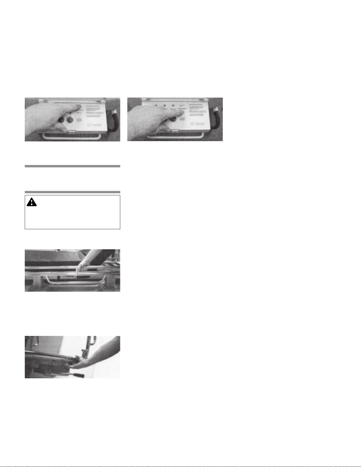
Nurse: Trendelenburg: Press the top button on the fourth row of buttons on the
control panel (Figure 3-22). Hold in the button until desired angle is achieved.
Rev-Trendelenburg: Press the bottom button on the fourth row of buttons on the
control panel (Figure 3-23). Hold in the button until the desired angle is achieved.
Patient: There is no Trendelenburg functions on the pendant.
Lockout
in the Section 3.6.1
Height Adjustment Instructions
.
Figure 3-22.
3.7 Airglide Rail Operation
WARNING–PERSONAL
INJURY HAZARD: Be sure
rail is locked before leaving
patient.
3.7.1. Raising the Rail
Figure 3-24.
Figure 3-23.
Grasp rail top tube from under litter top firmly, then pull up (Figure 3-24) until rail
locks into full up position.
3.7.2 Lowering the Rail
Firmly grasp top of rail, pull out on red tab, located under litter top at the foot
or head end (Figure 3-25). Lower side rail completely under litter top.
Figure 3-25.
3-10
069389 Operator Manual Operating Instructions
Page 19
3.8 Retracto Rail Operation
WARNING –PERSONAL
INJURY HAZARD: Be sure
rail is locked before leaving
patient.
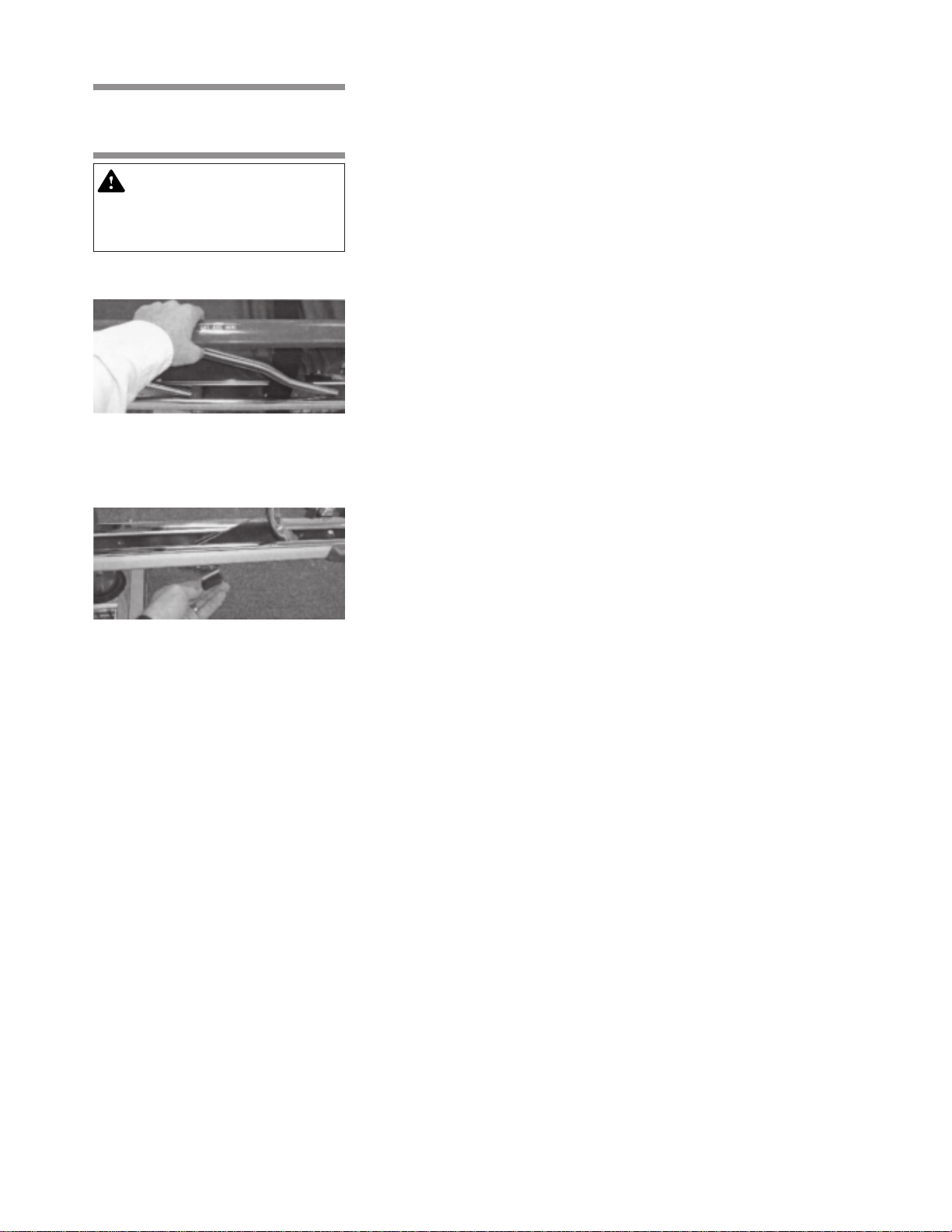
3.8.1 Raising the Rail Grasp the rail top cap in the middle of the rail (Figure 3-27) and lift.
Figure 3-27.
3.8.2 Half Height Grasp the rail, lift up on the red trigger under the liter top (Figure 3-28) while
lowering the rail. When rail starts to move down release trigger. Lower rail until
it locks into half height position.
Figure 3-28.
3.8.3 Lowering the Rail Grasp the rail, lift up on the red trigger under the top (Figure 3-28). While lowering
the rail, hold up on the trigger until the rail is all the way down.
3-11
Operating Instructions Operator Manual 069389
Page 20
3.9 Push Handle
Operation (Optional
Accessory)
3.9.1 Raising the Push Handles
Figure 3-29.
3.9.2 Lowering the Push Handles
3.10 Permanently
Mounted IV Rod
Operation
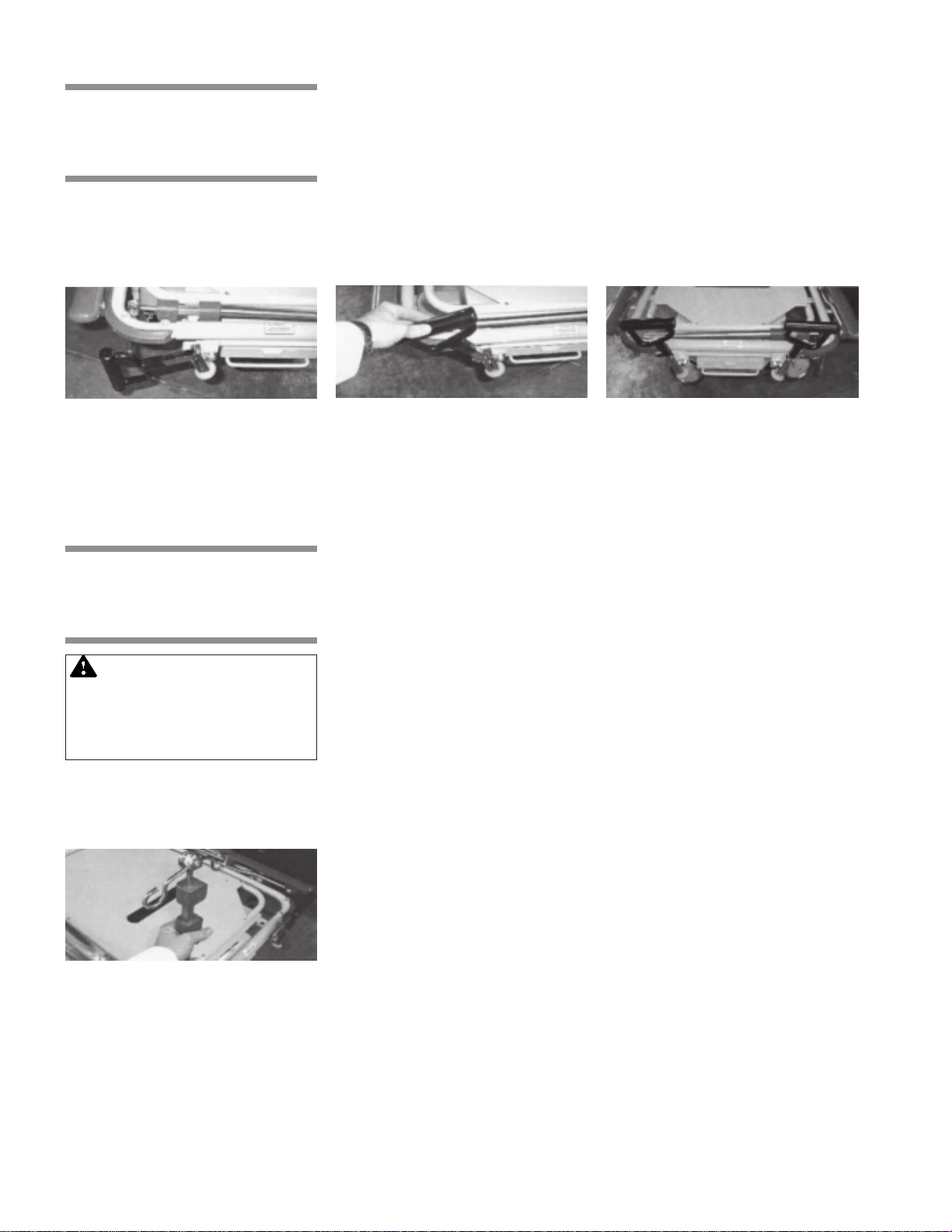
Hinge the push handle up (Figure 3-30) until it stops. Slide the push handle down
into the socket until it stops. Repeat process for handle on the other side. (Figure
3-31).
Figure 3-30.
Lift up on push handle and rotate (Figure 3-30) until it is in the down position
(Figure 3-29). Repeat process for the other side.
Figure 3-31.
WARNING–PERSONAL
INJURY HAZARD: Be sure
I.V. rod is inserted completely
into socket up to the arrow
before applying and load.
3.10.1 Putting I.V. Rod in Up Position
Figure 3-32.
Grasp I.V. rod and hinge upward until it stops (Figure 3-32). Push down on I.V.
rod until it slides firmly into the socket.
3-12
069389 Operator Manual Operating Instructions
Page 21
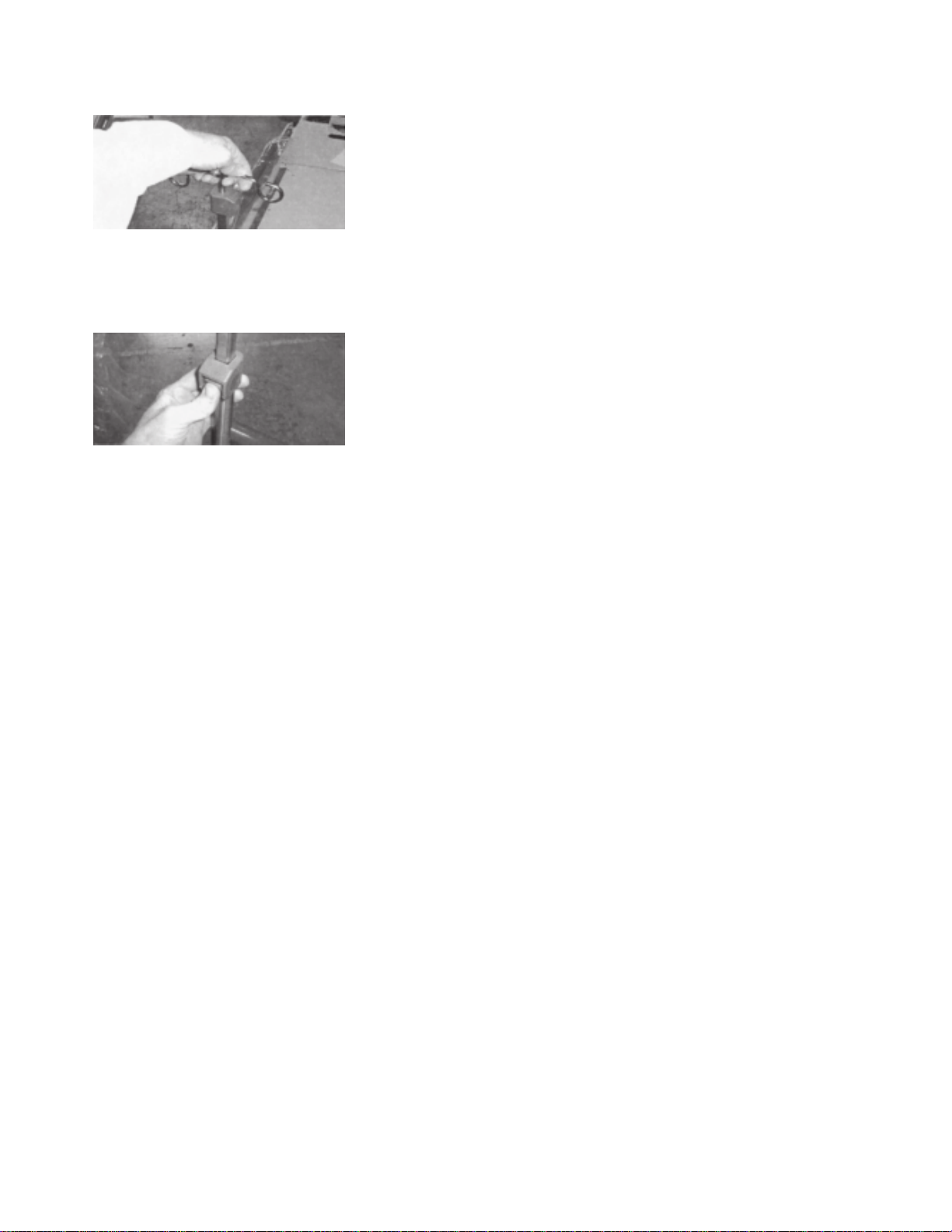
3.10.2 Extending I.V. Rod Lift up on top of I.V. rod (Figure 3-33) until desired length is achieved.
Figure 3-33.
3.10.3 Retracting I.V. Rod
Figure 3-34.
Press button located in the gray housing (Figure 3-34) and lower I.V. Rod until
desired height is achieved. Repeat process with second housing as required.
3-13
Operating Instructions Operator Manual 069389
Page 22
TROUBLE SHOOTING GUIDE
4.1 Electric Powered Stretchers
WARNING: To reduce the
risk of electric shock, do not
remove the cover. Unit is to
be serviced by qualified personnel only.
If Then
4
One motor or one column does not
move but all others are operating
correctly.
Nothing moves
The unit runs when plugged into
wall receptacle, but does not run
on the battery backup.
Step1: Check all motor and column plug connections at the controller box.
Step 2: If a column does not move: Check the the connection at the column.
Step 3: Plug a connector from the faulty component into a different socket:
If the component does not run:
– Replace that component.
If the component does run:
– Test pendant by plugging a functioning component into the non-
functioning socket on the controller. If this component does not run,
replace the pendant. If replacing the pendant does not fix the problem,
then the controller must be replaced.
Step 1: Plug unit into a mains supply wall receptacle, observe the pilot light
on the controller:
If the pilot light is off:
- Replace the controller
If the pilot light is on:
1. Check the nurse control plug connection at the controller.
2. Check the pendant control plug connection at the controller.
Step 1: Plug unit into a wall receptacle overnight. If the batteries do not hold
a charge, replace the batteries.
4-1
Troubleshooting Guide Operator Manual 069389
Page 23
4.2 Battery
Replacement
Instructions
WARNING– SHOCK HAZARD: To reduce the risk of
electric shock, do not remove
the cover. Unit is to be serviced by qualified personnel
only.
WARNING –PERSONAL INJURY HAZARD: The batteries are wired in series, failure to connect the same way
can cause the batteries to
explode.
The batteries are the only field serviceable components - do not attempt to repair the circuit boards.
Battery replacement Step 1: Remove the controller.
Step 2: Remove the 4 screws from the right half, located on top of the
controller.
Step 3: Replace (both) batteries with ‘YUSHA’ #NP 1.2-12, 12 volt, 1.2
Ah batteries.
(Steris P/N 075759 – 2 required.
Step 4: Be sure battery connector in in place on left side of batteries.
Step 5: Replace cover.
4-2
069389 Operator Manual Troubleshooting Guide
Page 24
8
8
8
8
8
8
8
8
8
RECOMMENDED PREVENTIVE MAINTENANCE
5
Procedure
Lubricate all moving and sliding parts
and hinge points.
23456789012345678901234567890121234567890123456789012345678901212345678901234567890123456789012123456789012345678901234567890121234567
23456789012345678901234567890121234567890123456789012345678901212345678901234567890123456789012123456789012345678901234567890121234567
23456789012345678901234567890121234567890123456789012345678901212345678901234567890123456789012123456789012345678901234567890121234567
23456789012345678901234567890121234567890123456789012345678901212345678901234567890123456789012123456789012345678901234567890121234567
23456789012345678901234567890121234567890123456789012345678901212345678901234567890123456789012123456789012345678901234567890121234567
23456789012345678901234567890121234567890123456789012345678901212345678901234567890123456789012123456789012345678901234567890121234567
23456789012345678901234567890121234567890123456789012345678901212345678901234567890123456789012123456789012345678901234567890121234567
23456789012345678901234567890121234567890123456789012345678901212345678901234567890123456789012123456789012345678901234567890121234567
23456789012345678901234567890121234567890123456789012345678901212345678901234567890123456789012123456789012345678901234567890121234567
>!< Never Lubricate Gas Spring, Motor and Mech-Lock Shafts >!<
position and tightness (including nuts,
Schedule
3 Months
3 MonthsInspect all fasteners to ensure proper fit,
Lubricating oil, light-duty
grease, wax stick lubricant.
Proper size wrench and screwdriver.
Material
!!
bolts, etc.).
3 MonthsInspect all surfaces and remove any
user developed sharp or burred areas.
Metal File, proper color paint
(specify color when ordering).
Apply touch-up where required.
5.1 Recommended
Cleaning
Instructions
NOTE: Steam cleaning and pressure washing of stretcher is not recommended
and can void warranty.
Component
Pads
Electric
Components
Mechanical
Stretcher
Components
Mechanical
Accessories
Cleaning Procedure
Wipe with Damp Cloth To remove
any foreign materials
Wipe with damp cloth to remove
any foreign materials
Wipe with damp cloth to remove
any foreign materials
Wipe with damp cloth to remove
any foreign materials
Schedule
After Each Use
After each use
After each use
After each use
For more details information, please contact:
Cleaning Agent
Routine Hospital Grade
Disinfectants, Soap
and Water
Routine hospital grade
disinfectants, soap and
water
Routine hospital grade
disinfectants, soap and
water
Routine hospital grade
disinfectants, soap and
water
STERIS Corporation at:
1-800-333-8828
Special Notes
• Use only medium strength cleaners
• Do not steam clean or pressure wash
• Use only medium strength cleaners
• Do not steam clean or pressure wash
• Be sure any wet surface on electic
components is dry before pulgging
into wall receptacle
• Lubricate pivot points after cleaning
• Lubricate pivot points after cleaning
5-1
Recommended Preventive Maintenance Operator Manual 069389
Page 25

OPTIONAL ACCESSORIES
Universal
000E17-00 Stainless steel 42" long fixed height I.V. rod - removable
000018-00 Stainless steel 27" to 54" long telescoping I. V. rod
128770-00 000018 - telescoping I.V. rod with cable attachment
126740-00 Infusion pump I.V. rod 1 1/8" dia - 42" long - removable
IVSTOW-00 Mobile I.V. stand attachment
Airglide Rail (D) Style Tops
066AGR-00 Mounted stainless telescoping I.V. rod - patient right
IVSTOW-00 Mobile I.V. stand attachment
Retracto Rail (H) Style Tops
066RR0-00 Mounted stainless telescoping I.V. rod - head end
065897-00 Mobile I.V. stand attachment
Airglide Rail (D) Style Tops
068965-60 Pressurecare - 4" x 32" x 77" conductive foam
069383-60 Enhanced pressurecare - 5" x 32" x 77" conductive foam
069230-00 Slick patient transfer mattress system
Retracto Rail (H) Style Tops
031661-60 3" x 29 1/2 “ x 76” conductive foam
061894-60 Pressurecare - 4" x 29 1/2" x 76" cond. foam - E & G tops
068922-60 Enhanced pressurecare - 5" x 29 1/2" x 76" -E & G tops
069206-00 Slick patient transfer mattress system
6
I.V. Poles
Pads and Matresses
Head and Foot Boards
Airglide Rail (D) Style Tops
000W6B-00 Head and foot board - stationary
0CRW6B-00 Head and foot board - stationary with chart rack
000W7B-00 Extension head and foot board
0CRW7B-00 Extension head and foot board - with chart rack
X-ray Accessories
Retracto Rail (H) Style Tops
000054-00 Lateral x-ray cassette holder- holds up to 14" x 17"
Monitor Shelves
Airglide Rail (D) Style Tops
069299-00 Extension footboard/monitor shelf w/chart rack
Retracto Rail (H) Style tops
00WN45-00 Monitor shelf - removable - folding
068846-00 Extension footboard/monitor shelf w/chart rack
6-1
Optional Accessories Operator Manual 069389
Page 26

Miscellaneous
Universal
000012-00 Restraint straps with buckle
000014-00 Restraint straps with velcro
128450-00 Vertical oxygen tank holder
065366-00 Universal patient tray
069257-00 Paper roll holder
Airglide Rail (D) Style Tops
075665-00 Self storing push handles
065180-00 Armboard - height adjustable - 1" pad included
00C16H-00 Heel stirrups
00C16L-00 Knee crutch stirrups
00L16M-00 Mounting adaptor clamps for heel stirrups/leg holders
067741-00 Side rail pads
068577-00 Burgundy pin striping for departmental identification
068578-00 Teal pin striping for departmental identification
068585-00 Plum pin striping for departmental identification
Retracto Rail (H) Style Tops
075656-00 Self storing push handles
133171-00 Under fowler utility tray
076334-00 Surgical armboard – pad & adapter included
00N16A-00 Heel stirrups
00N16C-00 Knee crutch stirrups
00N16E-00 Heel stirrups and leg holders with mounting adapter clamps
075626-00 Side rail pads
128840-00 Drainage bag hooks
131934-00 Burgundy bumpers and pin striping for department identification
131935-00 Teal bumpers and pin striping for department identification
131936-00 Plum bumper and pin striping for department identification
Fifth Wheels
4E2 Base (Electric)
075798-00 Fifth wheel, electric horizon auto track
4E1 (Hydraulic)
075797-00 Fifth wheel, horizon auto track
It is recommended that only STERIS approved accessories be used with this
device.
To order accessories or for more detailed information on accessories please
contact STERIS At: 1-800-428-7833
6-2
069389 Operator Manual Optional Accessories
Page 27

RECOMMENDED REPLACEMENT PARTS
7
7-1
Recommended Replacement Parts Operator Manual 069389
Page 28
35
68
42
49
56
33
41
57
43
20
40
39
55
37
34
32
12
Important Note: To reduce the risk of
electric shock, do not remove the cover.
Unit is to be serviced by qualified personnel
only.
For detailed plug locations, see Figures 7-9,
7-10, 7-18 & 7-19.
For detailed label locations, see Figures 7-11
& 7-20.
53
52
54
59
14
10
6
9
16
15
48
11
13
20
22
53
52
18
36
35
7
49
19
21
62
71
64
16
61
60
38
60
30
33
8
67
27
44
65
47
3
31
66
46
45
60
20
63
58
24
22
25
23
29
50
26
69
70
51
28
4
5
74
2
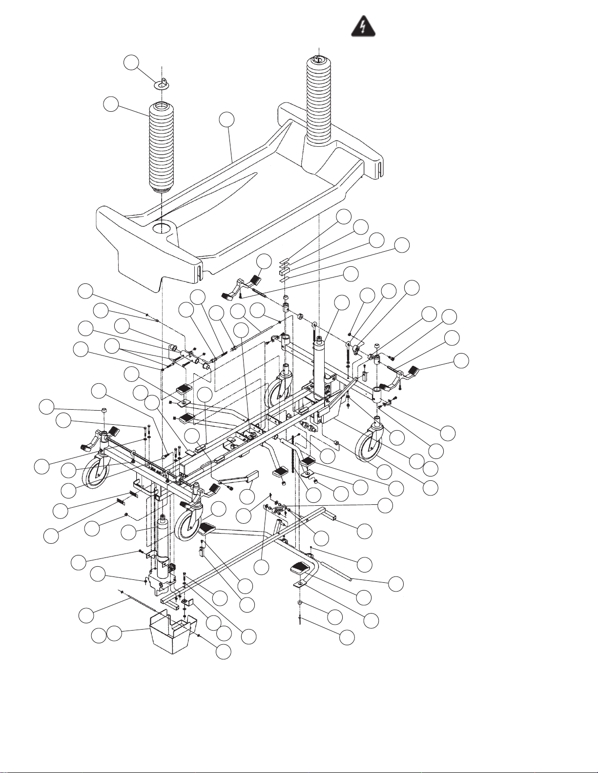
Figure 7-1. 4E1 Hydraulic Base Assembly
7-2
069389 Operator Manual Recommended Replacement Parts
Page 29
FIG. &
ITEM
NO.
7-1- 4E1 HYDRAULIC BASE ASSEMBLY ........................................ X
1 068331 ASSEMBLY, Base Frame ............................................................ 1
2 062672 CASTER, Tente, Brake................................................................ 3
3 062671 CASTER, Tente, Swivel Lock ...................................................... 1
4 062659 PLATE, Caster Bolt Lock ............................................................. 4
5 062685 SCREW, Hex Head Cap, M8 x 1.25 x 12.00" Long ..................... 8
6 065041 BOLT, Eye, 5/16-18 ..................................................................... 4
7 031058 NUT, Free Thread, 5/16" ............................................................. 4
8 031080 WASHER, Flat, 5/16" ................................................................... 8
9 031057 NUT, Lock, 5/16-18...................................................................... 6
10 062684 LEVER, Cam................................................................................ 2
11 068551 ROD, Horizon Hex Brake............................................................. 2
12 066507 ASSEMBLY, Left Brake Pedal ..................................................... 2
13 066508 ASSEMBLY, Right Brake Pedal .................................................. 2
14 031101 SCREW, Hex Cap w/Nylon, 1/4-20 x 3/4" Long .......................... 4
15 011422 COLLAR, Worm ........................................................................... 6
16 068207 JACK, Hydraulic, Foot End .......................................................... 1
17 068209 JACK, Hydraulic, Head End......................................................... 1
18 031412 SCREW, Hex Head Cap, 1/4-20 x 1-3/4" Long ........................... 8
19 031137 SCREW, Hex Head Cap, 1/4-20 x 3/4" Long .............................. 4
20 031076 WASHER, Flat, USS, 1/4"............................................................ 18
21 031055 NUT, Lock, 1/4-20........................................................................ 17
22 031156 BUMPER...................................................................................... 6
23 068368 ASSEMBLY, Jack Link................................................................. 1
24 068455 NYLINER, 5/16" ........................................................................... 4
25 068371 CONNECTOR, Pedal to Link ....................................................... 1
26 068345 ASSEMBLY, Pump Pedal ............................................................ 1
27 068126 NYLINER, 1/2" ............................................................................. 4
28 068379 BAR, Pump Pedal Hinge.............................................................. 1
29 031102 SCREW, Knurled Point Set, 1/4-20 x 1/4" Long .......................... 2
30 068355 GUIDE, Jack Link Vertical ........................................................... 1
31 068417 CUP, Rue, 5/16" .......................................................................... 2
32 068418 NYLINER, Type 7, 1/4" ................................................................ 2
33 031006 SCREW, Hex Head Cap, 1/4-20 x 1-1/2" Long ........................... 6
34 031321 SCREW, Hex Head Cap, 1/4-20 x 2" Long ................................. 1
35 031054 NUT, Free Thread, 1/4-20 ........................................................... 3
36 066705 BUMPER, Stop ............................................................................ 1
37 068374 LINK, Head End Release............................................................. 1
38 068375 LINK, Foot End Release .............................................................. 1
39 068378 COLLAR, Stop ............................................................................. 4
40 068128 SPRING, Long, 1-17/32".............................................................. 2
41 051308 NYLINER, 3/4" ............................................................................. 4
42 068353 CONNECTOR, Release Pedal .................................................... 2
43 068350 ASSEMBLY, Release Pedal, Left ................................................ 2
44 068351 ASSEMBLY, Release Pedal, Right.............................................. 2
45 068377 PLATE, Push ............................................................................... 2
46 068890 SCREW, Hex Head Cap, #10-32 x 1/2" Long ............................. 2
47 068329 LINK, Brake Rod .......................................................................... 1
48 065807 BOLT, Shoulder, 3/8" x 3/8"......................................................... 2
49 068530 WASHER, Nylon Shoulder .......................................................... 2
50 068343 PAD, Pump Pedal ........................................................................ 2
51 061164 PAD, Release Pedal
52 068513 HOOK, Velcro, 2.0" x 5/8"............................................................ 6
PART
NUMBER
S
V
C
DESCRIPTION
.................................................................... 4
UNITS PER
ASSEMBLY
continued on next page
7-3
Recommended Replacement Parts Operator Manual 069389
Page 30
FIG. &
ITEM
NO.
PART
NUMBER
S
V
DESCRIPTION
C
53 068512 PILE, Velcro, 2.0" x 5/8" .............................................................. 6
54 068376 SPACER, Cover........................................................................... 4
55 068208 BASE, Top Cover-Horizon ........................................................... 1
56 068550 BELLOWS, Gray, Round ............................................................. 2
57 066583 PLATE, Bellows Attachment ........................................................ 2
58 062378 CHAIN, Anti-Static ....................................................................... 1
59 068475 TAPE, Double Sided, 2.0" x 1/2" ................................................. 4
60 068380 TAPE, Polyethylene, 3/4" x 1 1/2" ............................................... 4
61 068381 TAPE, Polyethylene, 1/2" x 3/4" .................................................. 3
62 069282 ROD, Bottom Cover ..................................................................... 2
63 065611 NUT, Push, 3/16" ......................................................................... 4
64 065114 FOAM, Bottom Cover................................................................... 2
65 055620 PLUG, Hole .................................................................................. 4
66 035115 WASHER, Nylon, 5/16"................................................................ 2
67 031416 SCREW, Self Tapping, #10-24 x 1/2" Long ................................. 1
68 031371 GRIPRING, 1/4" ........................................................................... 2
69 000794 RIVET, Pop .................................................................................. 2
70 069281 COVER, Horizon Bottom, Head End ........................................... 1
71 069280 COVER, Horizon Bottom, Foot End............................................. 1
UNITS PER
ASSEMBLY
7-5
Recommended Replacement Parts Operator Manual 069389
Page 31
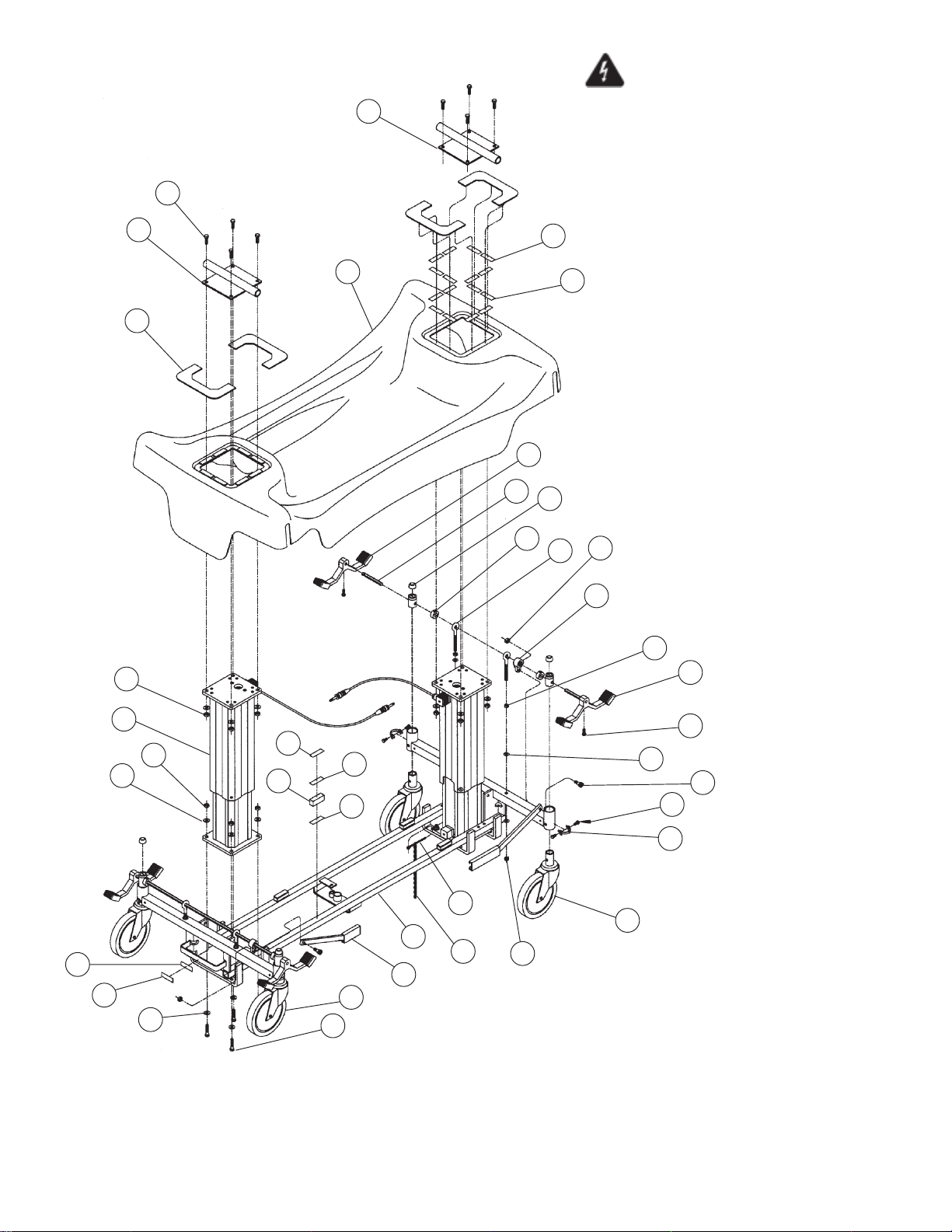
23
21
22
Important Note: To reduce the
risk of electric shock, do not remove the
cover.
Unit is to be serviced by qualified personnel only.
For detailed plug locations, see Figures
7-9, 7-10, 7-18 & 7-19.
For detailed label locations, see Figures
25
7-11 & 7-20.
16
27
228
11
9
9
8
25
24
26
31
15
13
17
24
9
6
10
7
12
14
8
20
5
4
29
2
1
24
25
30
19
3
8
18
9
Figure 7-2. 4E2/4D2 Electric Base Assembly
7-6
069389 Operator Manual Recommended Replacement Parts
Page 32
FIG. &
ITEM
NO.
PART
NUMBER
S
V
DESCRIPTION
C
7-2- 4E2/4D2 ELECTRIC BASE ASSEMBLY .................................... X
1 075457 ASSEMBLY, Base Frame ............................................................ 1
2 062672 CASTER, Tente, Brake................................................................ 3
3 062671 CASTER, Tente, Swivel Lock ...................................................... 1
4 062672 PLATE, Caster Bolt Lock ............................................................. 4
5 062685 SCREW, Hex Head Cap, M8 x 1.25 x 12.00" Long ..................... 8
6 065041 BOLT, Eye, 5/16-18 ..................................................................... 4
7 031058 NUT, Free Thread, 5/16-18 ......................................................... 4
8 031080 WASHER, Flat, 5/16" ................................................................... 28
9 031057 NUT, Lock, 5/16-18...................................................................... 16
10 062684 LEVER, Cam................................................................................ 2
11 068551 ROD, Horizon Hex Brake............................................................. 2
12 066507 ASSEMBLY, Left Brake Pedal ..................................................... 2
13 066508 ASSEMBLY, Right Brake Pedal .................................................. 2
14 031101 SCREW, Hex Head Cap, 1/4-20 x 3/4" Long .............................. 4
15 011422 COLLAR, Worm ........................................................................... 6
16 068983 COLUMN...................................................................................... 2
17 031156 BUMPER...................................................................................... 4
18 061350 SCREW, Hex Head Cap, 5/6 -18 x 1.50" Long ........................... 8
19 068329 LINK, Brake Rod .......................................................................... 1
20 065807 BOLT, Shoulder, 3/8" x 3/8"......................................................... 2
21 031012 SCREW, Hex Head Cap, 5/16-18 x 1.0" Long ............................ 8
22 075448 WELDMENT, Head End Crosstube ............................................. 1
23 075450 WELDMENT, Foot End Crosstube .............................................. 1
24 068513 HOOK, Velcro, 2.0" x 5/8"............................................................ 22
25 068512 PILE, Velcro, 2.0" x 5/8" .............................................................. 22
26 068376 SPACER, Cover........................................................................... 4
27 075006 COVER, Top, Electric Base ......................................................... 1
28 075006 SHROUD, Cover .......................................................................... 4
29 000894 TIE, Cable .................................................................................... 1
30 062378 CHAIN, Anti-Static ....................................................................... 1
31 068475 TAPE, Double Sided, 2.0" x 1/2" ................................................. 4
UNITS PER
ASSEMBLY
7-7
Recommended Replacement Parts Operator Manual 069389
Page 33
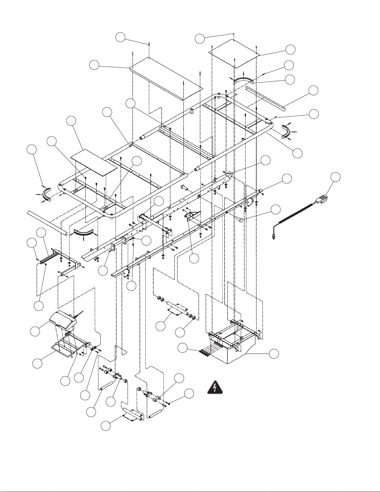
8
10
29
15
3
6
2
41
4
8
40
24
14
7
12
19
11
8
9
33
13
1
42
22
17
16
21
38
39
31
23
26
30
25
5
18
20
27
37
28
Important Note: To reduce the risk of electric
32
shock, do not remove the cover.
Unit is to be serviced by qualified personnel only.
For detailed plug locations, see Figures 7-9 & 7-10.
For detailed label locations, see Figures 7-11.
Figure 7-3. 4E2/4D2 – DPA Top Assembly
7-8
069389 Operator Manual Recommended Replacement Parts
Page 34
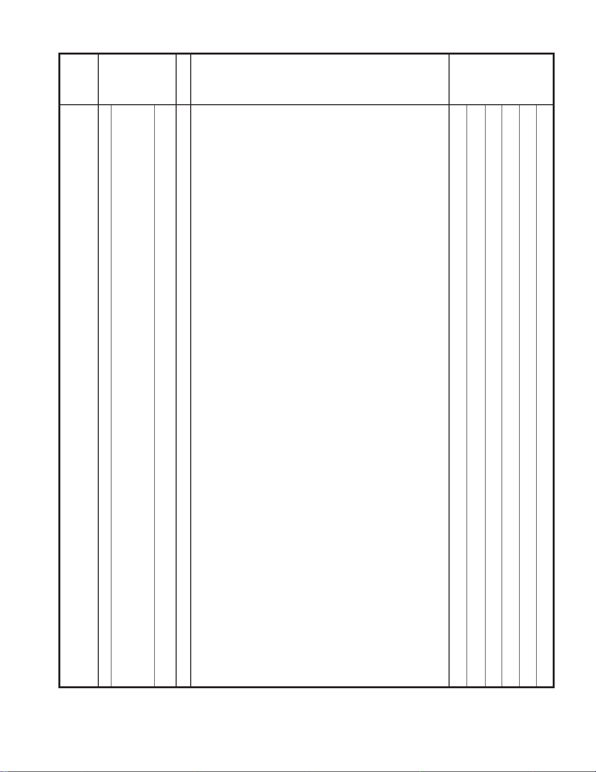
FIG. &
ITEM
NO.
7-3- 4E2/4D2 – DPA TOP ASSEMBLY ............................................. X
1 069221 * WELDMENT, Top, Head/Wide Top ............................................. 1
2 069225 * WELDMENT, Top, Foot/Wide...................................................... 1
3 069234 * TOP, Seat Sheet Pan/Wide .........................................................
4 067292 SCREW, Button Head Cap, 5/16-18 x 3/4" Long ........................ 10
5 031057 NUT, Lock, 5/16-18...................................................................... 22
6 031010 SCREW, Hex Head Cap, 5/16-18 x 3/4" Long ............................ 8
7 031080 WASHER, 5/16" ........................................................................... 12
8 000794 RIVET, Cherry, 3/16" x .45" ......................................................... 16
9 066540 BUMPER, Corner......................................................................... 4
10 061037 SCREW, Hex Head Self Tapping, #10-24 X 3/8" Long ............... 4
11 068484 ASSEMBLY, Top Angle, Right..................................................... 1
12 068483 ASSEMBLY, Top Angle, Left ....................................................... 1
13 031314 PIN, Spring, 3/16" x 3/4" .............................................................. 4
14 075012 ASSEMBLY, Lockout Support ..................................................... 1
15 061195 SCREW, Button Head Cap, 1/4-20 x 5/8" Long .......................... 4
16 031055 NUT, Lock, 1/4-20........................................................................ 16
17 075026 ASSEMBLY, Lockout Slide .......................................................... 1
18 075448 WELDMENT, Head End Crosstube ............................................. 1
19 068493 PLUG, Crosstube ......................................................................... 2
20 068464 COLLAR, Stop, 3/4" I.D. .............................................................. 6
21 075036 SCREW, Cheese Head Machine, M5-10 x 3/8" Long ................. 4
22 075716 BOX, Nurse Control ..................................................................... 1
23 031325 SCREW, Button Head Cap, 1/4-20 x 1.00" Long ........................ 4
24 075030 ANCHOR, Fowler Actuator .......................................................... 1
25 075022 ANCHOR, Foot Actuator .............................................................. 1
26 075450 WELDMENT, Foot End Crosstube .............................................. 1
27 068465 ROLLER....................................................................................... 4
28 061157 BOLT, Shoulder, 3/8" x 1.00" Long.............................................. 4
29 075740 COVER, Controller Top ............................................................... 1
30 068467 BRACKET, Roller Pivot................................................................ 2
31 068463 TUBE, Roller Stop........................................................................ 2
32 075033 ASSEMBLY, Controller, 4E2 (Before 12/98) ............................... 1
33 075236 PROTECTOR, Tube, Short.......................................................... 2
34 075233 PROTECTOR, Tube, Long (Not Shown) ..................................... 2
36 031076 WASHER, Flat, 1/4" ..................................................................... 4
37 068864 RELIEF, Small Strain ................................................................... 6
38 068863 GLIDE, Plastic.............................................................................. 4
39 066925 SCREW, Flat Head Socket, 1/4-20 x 1.00" Long ........................ 4
40 068475 TAPE, Double Sided, 1/4" x 2.0" ................................................. 4
41 075041 COVER, Nurse Control Panel...................................................... 1
42 075741 ASSEMBLY, Pendant, (CB-14 Version) ...................................... 1
PART
NUMBER
075737 ASSEMBLY, Controller, 4E2 (10/98-5/00)................................... 1
076131 ASSEMBLY, Controller, 4E2 (After 5/00) .................................... 1
076182 ASSEMBLY, Controller, 230V, 4D2 (After 5/00) .......................... 1
075739 ASSEMBLY, Controller, 230V, 4D2 (10/98-5/00) ........................ 1
075046 ASSEMBLY, Pendant, (CB-10 Version) ...................................... 1
S
V
C
DESCRIPTION
UNITS PER
ASSEMBLY
NOTE: The “O” suffix on the part numbers marked with an
“ * ” designate part numbers for the chrome/stainless units
(Model 4E2 DPA-SS). For powder coated units (Model 4E2
DPA-PC), the “O” suffix should be relace with a “P” suffix.
(Example: Item 1 for a powder coated unit 4E2 DPA-PC,
would become P69221).
7-9
Recommended Replacement Parts Operator Manual 069389
Page 35
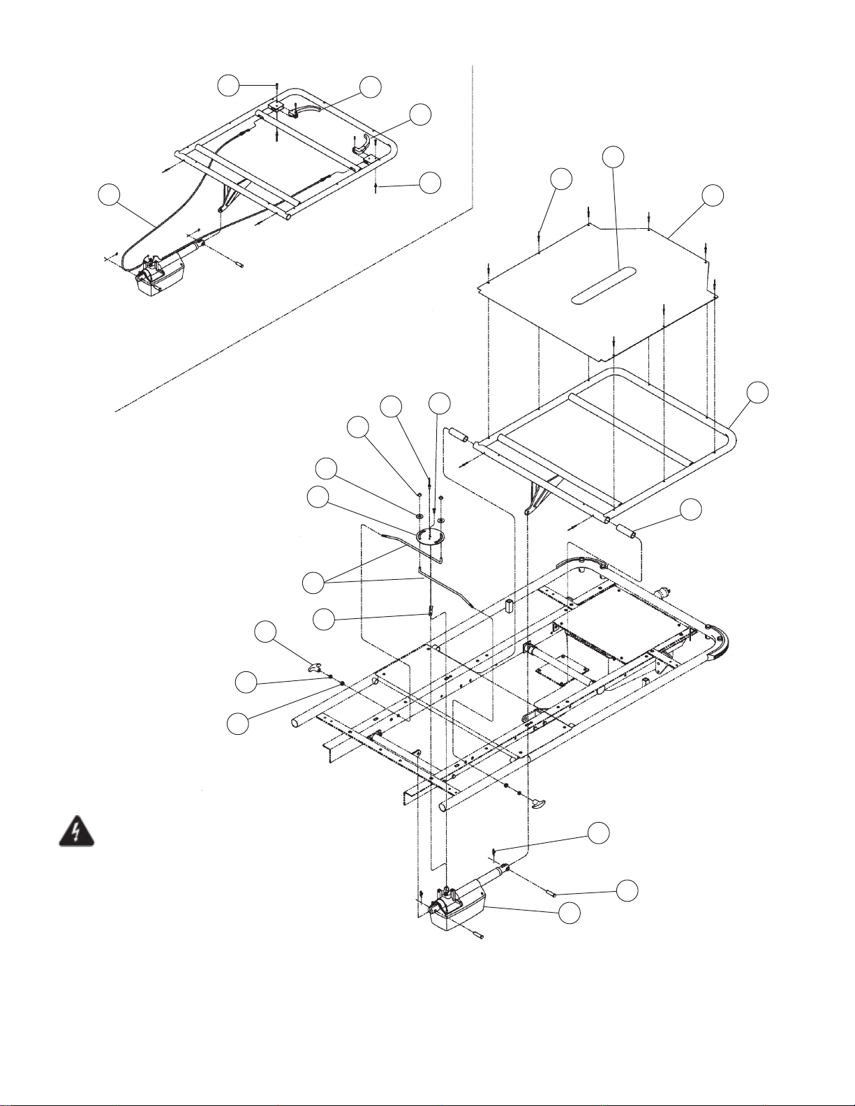
22
23
Cable Style Quick Drop
Used only on models prior to 11/97
21
20
19
7
18
3
16
15
14
18
4
17
5
6
13
11
2
1
Important Note: To reduce the risk of electric
10
shock, do not remove the cover.
Unit is to be serviced by qualified personnel only.
For detailed plug locations, see Figures 7-9 & 7-10.
For detailed label locations, see Figures 7-11.
8
9
Figure 7-4. 4E2/4D2 – DPA Fowler Assembly
7-10
069389 Operator Manual Recommended Replacement Parts
Page 36
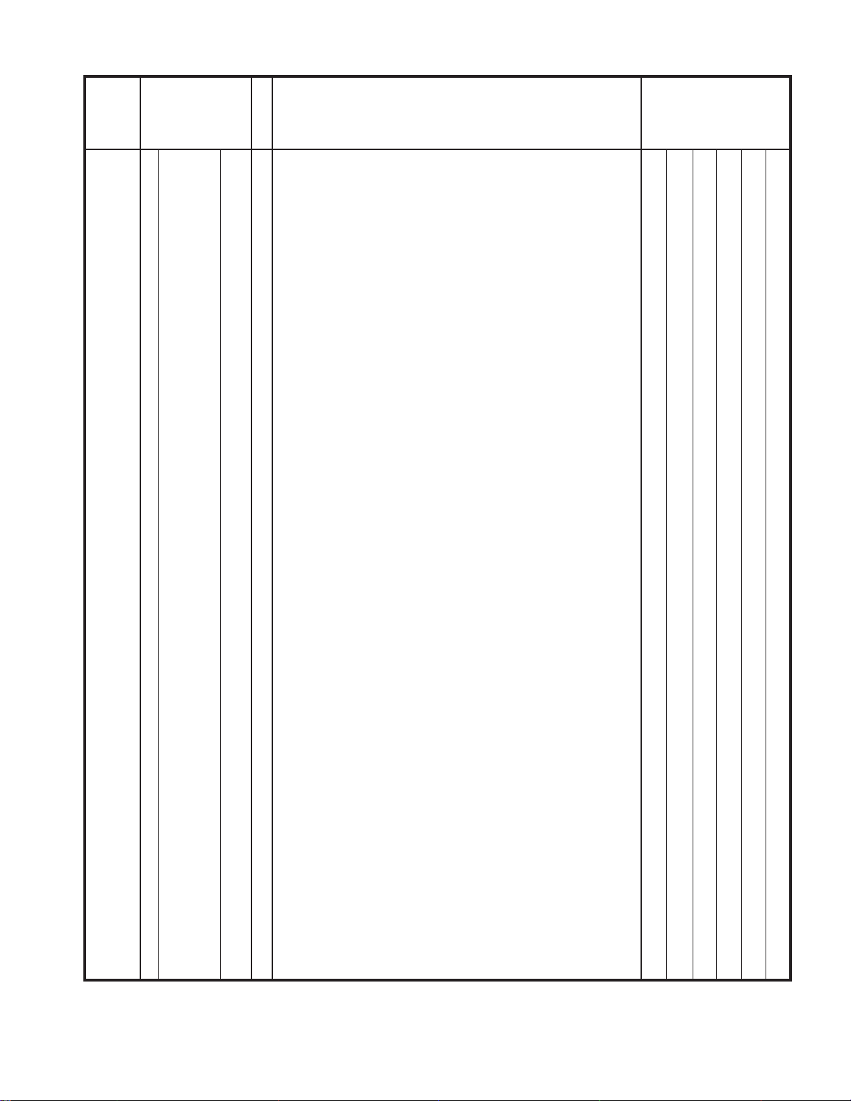
FIG. &
ITEM
NO.
7-4- 4E2/4D2 – DPA FOWLER ASSEMBLY ...................................... X
1 075015 * FRAME, Fowler, Electric, Wide ................................................... 1
2 066696 PIN, Fowler Hinge........................................................................ 1
3 069237 * SHEET, Fowler Cover, Wide ....................................................... 1
4 075443 NUT, Cap, 1/4"............................................................................. 2
5 075437 PLATE, Actuator .......................................................................... 1
6 075442 ROD, Pull ..................................................................................... 1
7 031212 HOOK, Velcro .............................................................................. 1
8 068985 ACTUATOR, Fowler Backrest ..................................................... 1
9 075627 PIN, Gas Spring Hinge................................................................. 2
10 065258 CLIP, Rue, 3/8" ............................................................................ 2
11 075444 SCREW, Slotted Pan Head, M5 x 20MM .................................... 1
12 069440 RIVET, Pop, Steel, 3/16" ............................................................. 2
13 075441 SPACER ...................................................................................... 1
14 055215 KNOB, Pull ................................................................................... 2
15 031054 NUT, Free Thread, 1/4-20 ........................................................... 2
16 061336 BEARING, Nylon.......................................................................... 2
17 065688 WASHER, Nylon, 5/16"................................................................ 2
18 000794 RIVET, Pop, Aluminum, 3/16"...................................................... 9
19 031186 RIVET, Stop ................................................................................. 2
20 066547 PIN, Straight, 3/16" x 1/2" ............................................................ 2
21 075042 HANDLE, Fowler.......................................................................... 2
22 066548 PIN, Clevis, 3/16" x 7/8"............................................................... 2
23 075032 CABLE, Fowler Quick Release .................................................... 2
PART
NUMBER
S
V
C
DESCRIPTION
UNITS PER
ASSEMBLY
NOTE: The “O” suffix on the part numbers marked with an
“ * ” designate part numbers for the chrome/stainless units
(Model 4E2 DPA-SS). For powder coated units (Model 4E2
DPA-PC), the “O” suffix should be relace with a “P” suffix.
(Example: Item 1 for a powder coated unit 4E2 DPA-PC,
would become P75015).
7-11
Recommended Replacement Parts Operator Manual 069389
Page 37
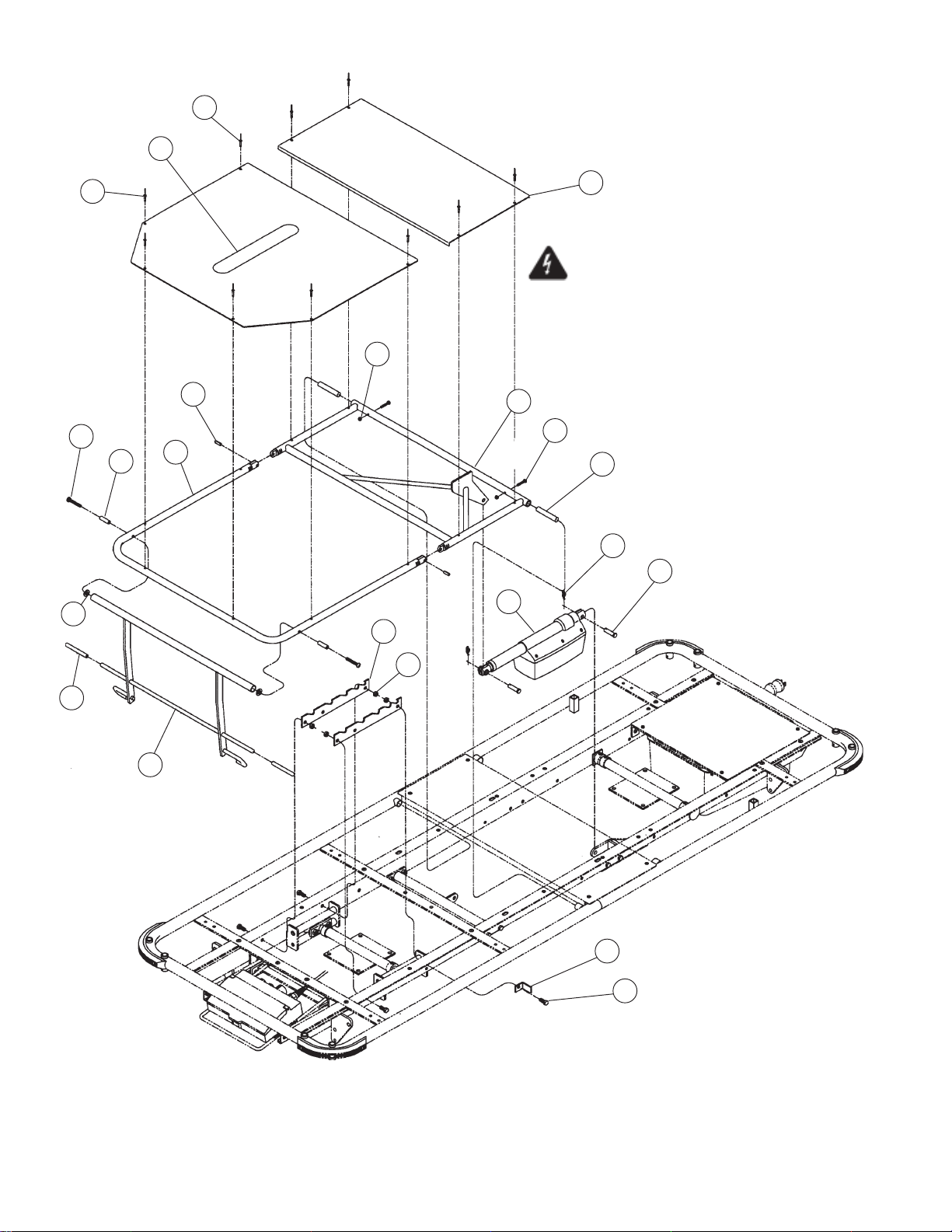
20
4
19
5
Important Note: To reduce the risk of electric
shock, do not remove the cover.
Unit is to be serviced by qualified personnel only.
For detailed plug locations, see Figures 7-9 & 7-10.
22
18
6
7
8
2
14
For detailed label locations, see Figures 7-11.
1
21
17
13
12
11
16
9
3
10
15
Figure 7-5. Leg Section Assembly
7-12
069389 Operator Manual Recommended Replacement Parts
Page 38
FIG. &
ITEM
NO.
PART
NUMBER
S
V
DESCRIPTION
C
7-5- LEG SECTION ASSEMBLY........................................................ X
1 P69226 WELDMENT, Knee Frame, Wide Top ......................................... 1
2 P69232 ASSEMBLY, Foot Frame, Wide Top............................................ 1
3 069229 TOP, Kneeflex Foot Support/Wide .............................................. 1
4 P69236 TOP, Foot Section Cover Sheet/Wide ......................................... 1
5 P69235 TOP, Knee Section Cover Sheet/Wide ........................................ 1
6 031357 SCREW, Phillips Oval Head, 1/4-20 x 1-3/4" Long ..................... 2
7 067149 SPACER, Foot Frame.................................................................. 2
8 035115 WASHER, Nylon .......................................................................... 2
9 066688 CAP, Vinyl .................................................................................... 2
10 067143 STOP, Foot Support .................................................................... 1
11 068986 ACTUATOR, Leg Rest .................................................................
12 075627 PIN, Gas Spring Hinge................................................................. 2
13 065258 CLIP, Rue 3/8" ............................................................................. 2
14 065059 PLATE, Ratchet ........................................................................... 2
15 031010 SCREW, Hex Head Cap, 5/16-18 x 3/4" Long ............................ 4
16 031057 NUT, Lock, 5/16-18...................................................................... 4
17 030432 SHAFT, Cross Bar ....................................................................... 2
18 031312 PIN spring, 1/4" x 3/4".................................................................. 2
19 000794 RIVET, Cherry, 3/16" x .45" ......................................................... 10
20 031212 HOOK, Velcro .............................................................................. 1
21 075502 SCREW, Phillips Pan Head, #10-24 x 1-1/8" Long ..................... 2
22 031421 NUT, Lock, #10-24....................................................................... 2
UNITS PER
ASSEMBLY
7-13
Recommended Replacement Parts Operator Manual 069389
Page 39
15
12
6
1
8
2
3
9
10
11
13
19
14
16
5
23
18
4
17
22
21
20
NOTE: Only one side of rail and one
side of latch is shown for clarity, the bill
of material reflects parts required for a
complete stretcher.
For detailed plug locations, see Figures 7-9, 7-10, 7-18 & 7-19.
For detailed label locations, see Figures 7-11 & 7-20.
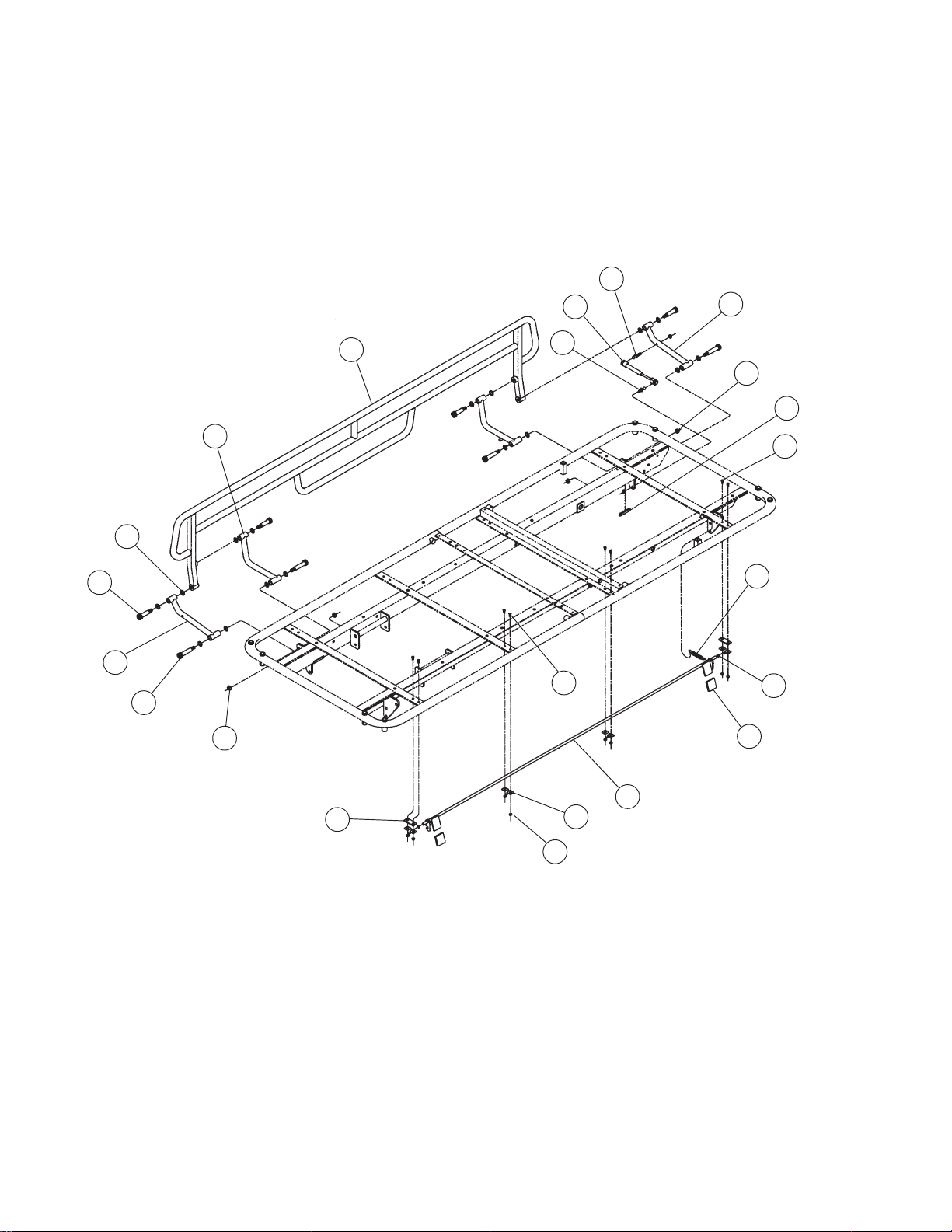
Figure 7-6. Airglide Rail Assembly
7-14
069389 Operator Manual Recommended Replacement Parts
Page 40
FIG. &
ITEM
NO.
PART
NUMBER
S
V
DESCRIPTION
C
7-6- AIRGLIDE RAIL ASSEMBLY...................................................... X
1 068453 WELDMENT, Air Glide Rail ......................................................... 2
2 066619 WASHER, Nylon .......................................................................... 32
3 066616 BOLT, Shoulder, 1/2" x 1-1/2" Long ............................................ 8
4 066613 CAP, Rail Latch............................................................................ 4
5 031325 SCREW, Button Head Cap, 1/4-20 x 1/2" Long .......................... 8
6 066595 LINK, Lower, Left ......................................................................... 2
7 066589 LINK, Upper, Left .........................................................................
8 066590 LINK, Upper, Right....................................................................... 2
9 066595 LINK, Lower, Right....................................................................... 2
10 062037 BOLT, Shoulder, 1/2" x 2.0"......................................................... 8
11 066618 NUT, Lock, 3/8-16........................................................................
12 067711 STUD, Long Ball .......................................................................... 2
13 067712 STUD, Short Ball.......................................................................... 2
14 031057 NUT, Lock, 5/16-18...................................................................... 4
15 067709 SPRING, 175 Newton Gas .......................................................... 2
16 066983 LOCK, Trim .................................................................................. 4
17 067131 ASSEMBLY, Rail Latch................................................................ 2
18 061375 WASHER, Nylon .......................................................................... 4
19 061195 SCREW, Button Head Cap, 1/4-20 x 5/8" Long .......................... 8
20 031055 NUT, Lock, 1/4-20........................................................................ 16
21 067136 SUPPORT, Latch Tube................................................................ 8
22 066605 PLATE, Latch Support ................................................................. 4
23 066603 SPRING, Latch ............................................................................ 2
UNITS PER
ASSEMBLY
7-15
Recommended Replacement Parts Operator Manual 069389
Page 41
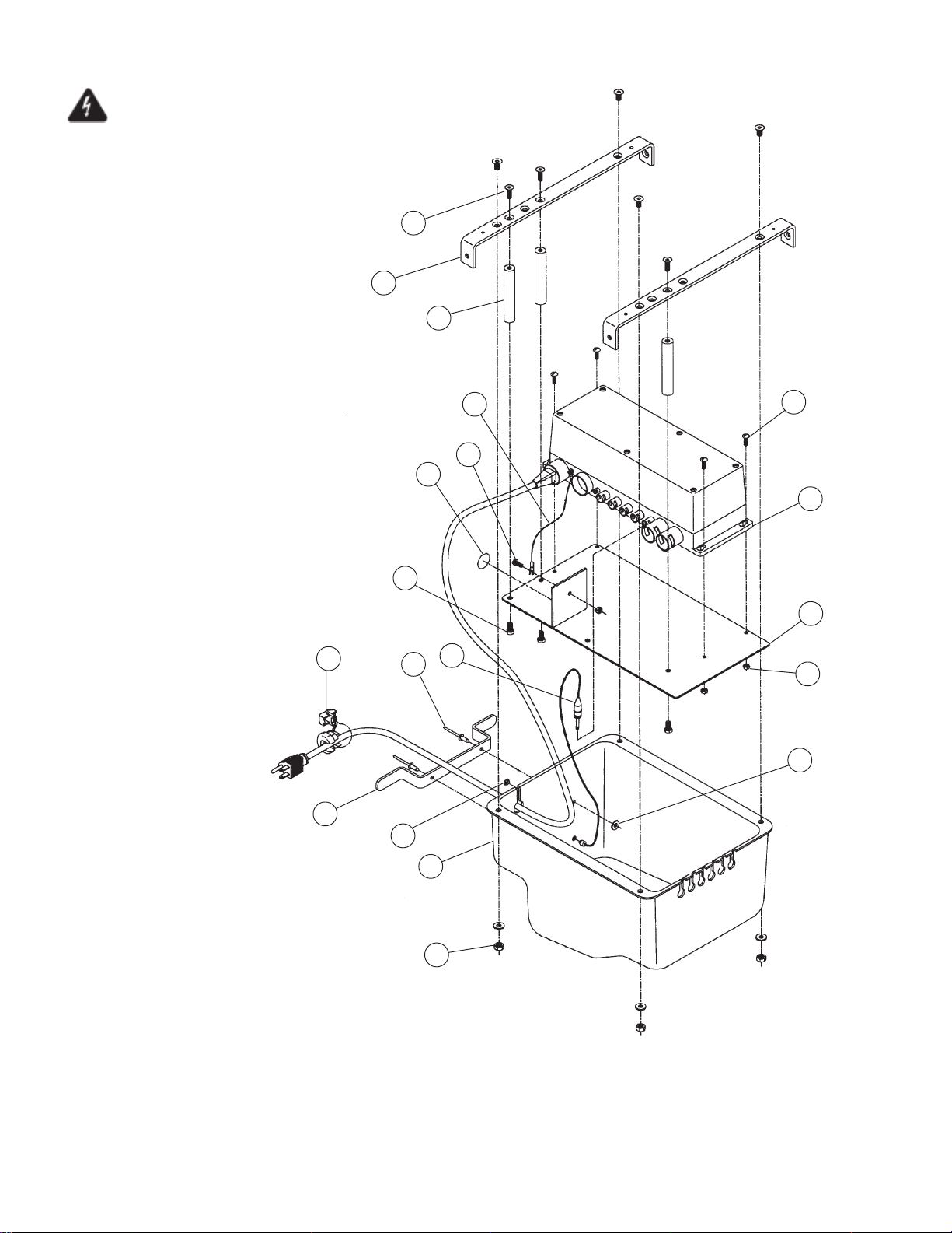
Important Note: To reduce the risk of electric
shock, do not remove the cover.
Unit is to be serviced by qualified personnel only.
For detailed plug locations, see Figures 7-9 & 7-10.
For detailed label locations, see Figures 7-11.
2
9
5
15
14
13
17
18
6
3
16
3
7
4
1
8
11
10
12
Figure 7-7. 4E2/4D2 – DPA Controller Assembly (After 5/1/00)
7-16
069389 Operator Manual Recommended Replacement Parts
Page 42
FIG. &
ITEM
NO.
PART
NUMBER
S
V
DESCRIPTION
C
7-7- 4E2/4D2 – DPA CONTROLLER ASSEMBLY (AFTER 5/1/00) .. X
1 076133 WELDMENT, Controller Hanger Plate......................................... 1
2 075736 STRAP, Controller Hanger .......................................................... 2
3 075749 ASSEMBLY, Low Battery LED..................................................... 1
4 075044 CONTROLLER, CB-14, 120VAC, 4E2 Models............................ 1
075718 CONTROLLER, CB-14, 230VAC, 4D2 Models ........................... 1
5 075735 POST, Mounting .......................................................................... 3
6 031004 SCREW, Hex Head Cap, 1/4-20 x 1/2" Long .............................. 3
7 061159 SCREW, Truss Head Mach, #10-24 x 5/8" Long......................... 4
8 031421 NUT, Lock, #10 ............................................................................ 5
9 031324 SCREW, Flat Head Mach, 1/4-20 x 1/2" Long............................. 7
10 075732 COVER, Controller....................................................................... 1
11 031074 WASHER, Flat, 3/16" ................................................................... 2
12 031055 NUT, Lock, 1/4-20........................................................................ 4
13 076125 WIRE, Controller Ground ............................................................. 1
14 068982 RELIEF, Strain ............................................................................. 1
15 076123 BRACKET, Cord Wrap................................................................. 1
16 000794 RIVET, 3/16" ................................................................................ 2
17 031000 SCREW, Hex Washer Head, #10-24 x 1/2"................................. 1
18 076132 LABEL, Ground Symbol............................................................... 1
UNITS PER
ASSEMBLY
7-17
Recommended Replacement Parts Operator Manual 069389
Page 43
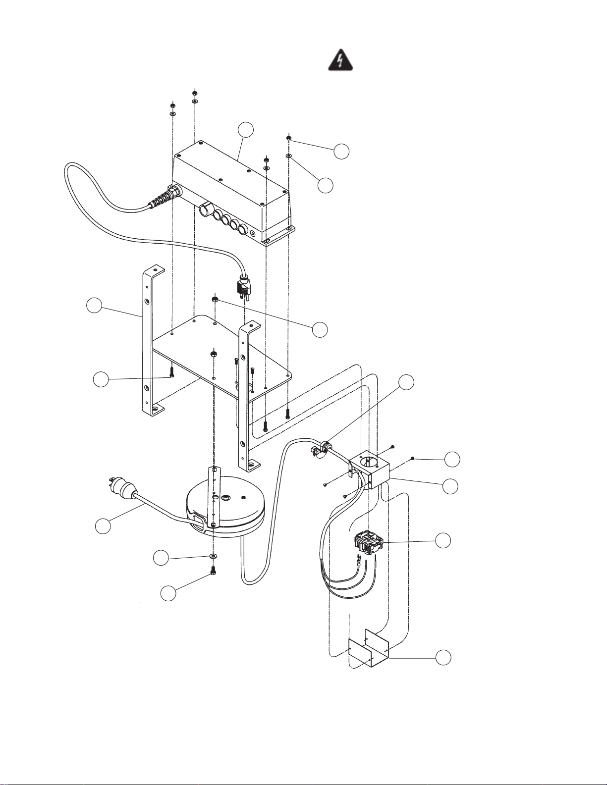
Important Note: To reduce the risk of electric
shock, do not remove the cover.
Unit is to be serviced by qualified personnel only.
For detailed plug locations, see Figures 7-9 & 7-10.
For detailed label locations, see Figures 7-11.
12
5
4
1
9
3
6
8
7
12
14
10
11
13
Figure 7-8. DPA Controller Assembly (Before 5/1/00)
7-18
069389 Operator Manual Recommended Replacement Parts
Page 44
FIG. &
ITEM
NO.
PART
NUMBER
S
V
DESCRIPTION
C
7-8- DPA CONTROLLER ASSEMBLY (BEFORE 5/1/00) ................. X
1 075009 Controller Hanger ........................................................................ 1
2 068962 CONTROLLER, CB-10 (Before 10/98) ........................................ 1
075044 CONTROLLER, CB-14 (After 10/98) ........................................... 1
075467 CONTROLLER, CB-10, 230 VAC, 4D2 (Before 10/98) ............... 1
075718 CONTROLLER, CB-14, 230 VAC, 4D2 (After 10/98) .................. 1
3 031003 SCREW, Hex Slotted Head Cap, #10-24 x 3/4" Long ................. 4
4 031074 WASHER, Flat, #10 ..................................................................... 4
5 031421 NUT, Lock, #10 ............................................................................ 4
6 068966 REEL, Cord .................................................................................. 1
7 031017 SCREW, Hex Head Cap, 1/4-20 x 1.00" Long ............................ 2
8 031364 WASHER, Flat, 1/4" ..................................................................... 2
9 031055 NUT, Lock, 1/4-20........................................................................ 2
10 068979 BASE, Junction Box Base ........................................................... 1
11 068976 RECEPTACLE, Hospital Grade ................................................... 1
12 068982 RELIEF, Strain ............................................................................. 1
13 068980 COVER, Junction Box.................................................................. 1
14 031097 SCREW, Sheet Metal, #6 x 1/4" Long ......................................... 4
UNITS PER
ASSEMBLY
7-19
Recommended Replacement Parts Operator Manual 069389
Page 45
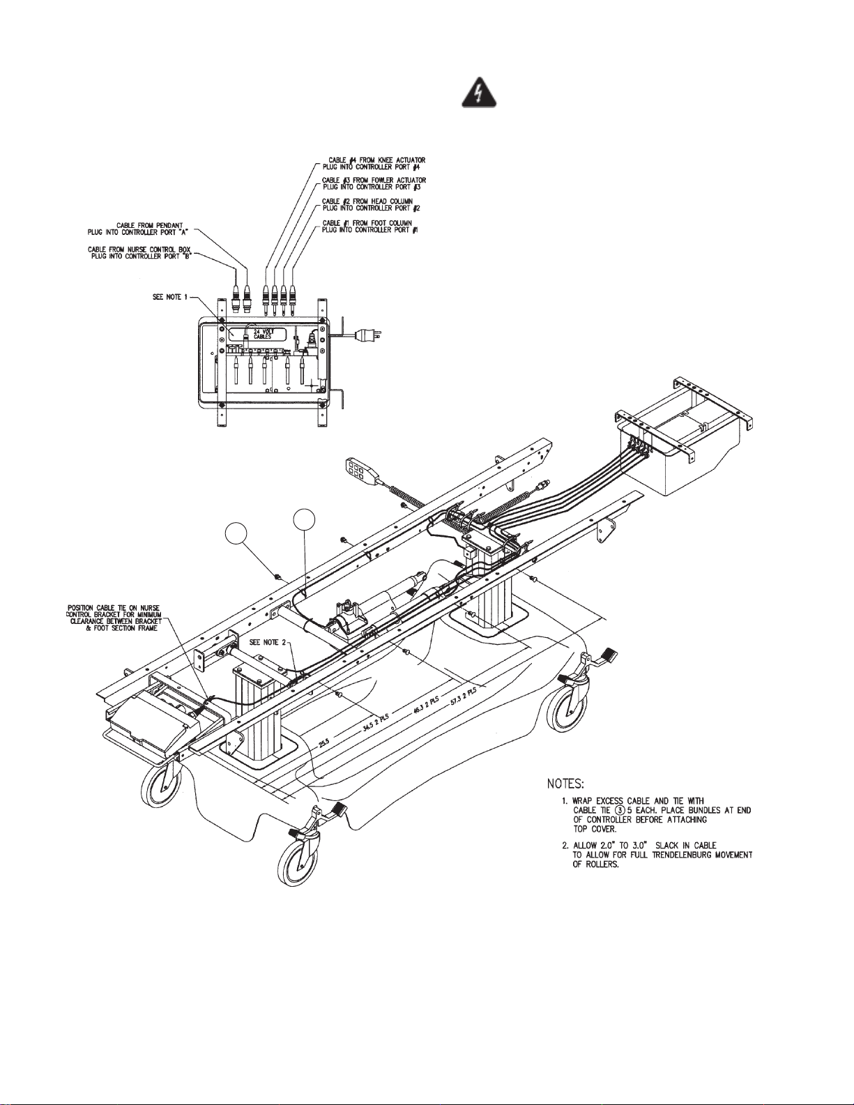
Important Note: To reduce the risk of electric
shock, do not remove the cover.
Unit is to be serviced by qualified personnel only.
For detailed label locations, see Figures 7-11.
1
2
Figure 7-9. DPA Plug and Wiring Diagram (After 5/1/00)
7-20
069389 Operator Manual Recommended Replacement Parts
Page 46
FIG. &
ITEM
NO.
PART
NUMBER
S
V
DESCRIPTION
C
7-9-
1 063031 BUTTON ...................................................................................... 7
2 065403 TIE, Cable (Large) ....................................................................... 20
UNITS PER
ASSEMBLY
7-21
Recommended Replacement Parts Operator Manual 069389
Page 47
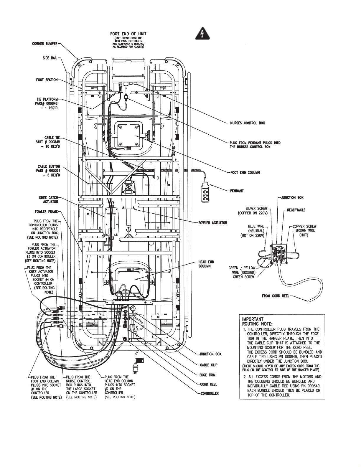
Important Note: To reduce the risk of electric
shock, do not remove the cover.
Unit is to be serviced by qualified personnel only.
For detailed label locations, see Figures 7-11.
Figure 7-10. DPA Plug and Wiring Diagram (Before 5/1/00)
7-22
069389 Operator Manual Recommended Replacement Parts
Page 48
FIG. &
ITEM
NO.
PART
NUMBER
S
V
DESCRIPTION
C
7-10 DPA PLUG AND WIRING DIAGRAM (BEFORE 5/1/00)
UNITS PER
ASSEMBLY
7-23
Recommended Replacement Parts Operator Manual 069389
Page 49
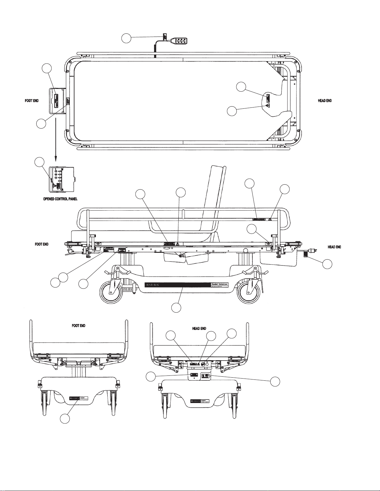
16
14
11
13
Both Sides
12
Both Sides
16
3
6
Both Sides
10
16
Both Sides
Both Sides/
Both Ends
4
5
15
17
3
Both Sides
1
6
7
9
8
18
2
Figure 7-11. 4E2 – DPA Label Locations
7-24
069389 Operator Manual Recommended Replacement Parts
Page 50
FIG. &
ITEM
NO.
PART
NUMBER
S
V
DESCRIPTION
C
7-11- 4E2 – DPA LABEL LOCATIONS ................................................ X
4D2 – DPA LABEL LOCATIONS................................................ X
1 075836 LABEL, Side-Electric Stretcher .................................................... 2 2
2 075831 LABEL, Base End ........................................................................ 2 2
3 068855 LABEL, Electric Service ............................................................... 2 2
4 076127 LABEL, Serial Number, 110V Electric ......................................... 1 –
075475 LABEL, Serial Number, 230V Electric ......................................... – 1
5 031458 OVERLAY, Clear Mylar................................................................ 1 1
6 075478 LABEL, Dangerous Voltage ......................................................... 2 2
7 075484 LABEL, Unplug Before Servicing ................................................. 1 1
8 055025 LABEL, Hospital Grade Receptacle............................................. 1 –
9 066716 LABEL, Rail Release ................................................................... 4 4
10 066717 LABEL, Rail Operation ................................................................. 2 2
11 075035 LABEL, Control Panel .................................................................. 1 1
12 075040 LABEL, Emergency Release ....................................................... 2 2
13 075489 LABEL, Pendant .......................................................................... 1 1
14 075589 LABEL, Maximum Weight, 625 pounds ....................................... 1 1
15 063022 LABEL, Service ............................................................................ 1 1
16 075479 LABEL, Hazardous Area.............................................................. 5 5
17 075748 LABEL, Low Battery..................................................................... 1 1
18 061815 LABEL, ETL Listing...................................................................... 1 –
UNITS PER
ASSEMBLY
7-25
Recommended Replacement Parts Operator Manual 069389
Page 51
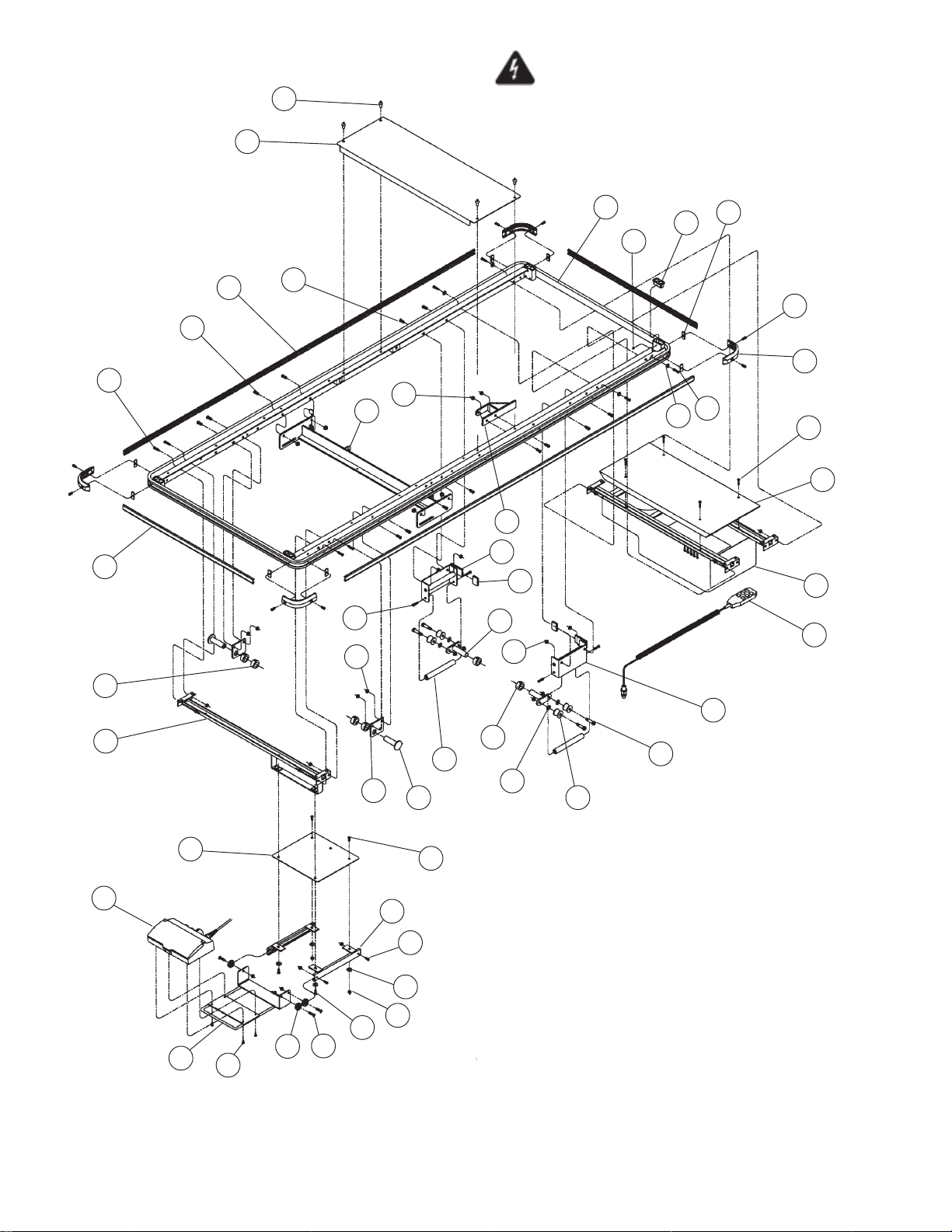
11
12
Important Note: To reduce the risk of electric
shock, do not remove the cover.
Unit is to be serviced by qualified personnel only.
For detailed plug locations, see Figures 7-18 & 7-19.
For detailed label locations, see Figures 7-20.
1
41
10
34
27
9
34
27
4
36
35
3
28
25
4
4
39
40
8
7
6
27
38
37
33
42
15
14
30
16
31
17
14
26
5
13
7
29
7
24
22
NOTE: The “O” suffix on the part numbers marked with an
“ * ” designate part numbers for the chrome/stainless units
(Model 4E2 DPA-SS). For powder coated units (Model 4E2
DPA-PC), the “O” suffix should be relace with a “P” suffix.
(Example: Item 1 for a powder coated unit 4E2 DPA-PC,
would become P75413).
18
19
32
20
31
Figure 7-12. 4E2/4D2 – HMC Top Assembly
2
23
7-26
069389 Operator Manual Recommended Replacement Parts
Page 52
FIG. &
ITEM
NO.
PART
NUMBER
S
V
DESCRIPTION
C
7-12- 4E2/4D2 – HMC TOP ASSEMBLY ............................................. X
*1 075413 WELDMENT, Top ........................................................................ 1
2 068461 ASSEMBLY, Roller Bracket, Right .............................................. 1
3 068536 ASSEMBLY, Roller Bracket, Left ................................................. 1
4 031057 NUT, Lock, 5/16-18...................................................................... 18
5 068481 PLATE, Foot End Support ........................................................... 2
6 067958 BUMPER, Corner......................................................................... 4
7 061195 SCREW, Button Head Cap, 1/4-20 x 5/8" Long .......................... 12
8 031455 NUT, Channel, 1/4-20 .................................................................. 8
9 068154 EXTENSION, End Bumper, Gray ................................................ 2
10 13193U EXTENSION, End Bumper, Red.................................................. 2
13193V EXTENSION, End Bumper, Blue ................................................. 2
13193W EXTENSION, End Bumper, Green .............................................. 2
067959 EXTENSION, Side Bumper, Gray................................................ 2
*11 067960 EXTENSION, Side Bumper, Red................................................. 2
067961 EXTENSION, Side Bumper, Blue ................................................ 2
067964 EXTENSION, Side Bumper, Green ............................................. 2
062215 COVER, Seat Section.................................................................. 1
12 055213 RIVET, 1/4" x 1/2" ........................................................................ 4
13 068493 PLUG, Crosstube ......................................................................... 2
14 068464 COLLAR, Shaft, 3/4" .................................................................... 6
15 075716 BOX, Nurse Control ..................................................................... 1
16 P75093 ASSEMBLY, Lock Out Slide ........................................................ 1
17 075036 SCREW, Cheese Head, M5 x .8 x 10 mm Long .......................... 4
18 068663 GLIDE, Plastic.............................................................................. 3
19 066925 SCREW, Flat Head Cap, 1/4-20 x 1.0" Long ............................... 3
20 031364 WASHER, Flat, 1/4" ..................................................................... 2
21 031055 NUT, Lock, 1/4-20........................................................................ 15
22 068465 ROLLER....................................................................................... 4
23 061157 BOLT, Shoulder, 3/8" x 1.00"....................................................... 4
24 035115 WASHER, Nylon 3/8" I.D. ............................................................ 4
25 068467 BRACKET, Roller Pivot................................................................ 2
26 068463 TUBE, Roller Stop........................................................................ 2
27 031325 SCREW, Button Head Socket, 1/4-20 x 1.00" Long .................... 1 2
28 068538 CAP, Fowler Stop ........................................................................ 2
29 P75096 TRACK, Lock Out Support ........................................................... 2
30 075416 HANGER, Nurse Control ............................................................. 1
31 P75466 COVER, Nurse Control Top ......................................................... 1
32 068786 SCREW, Hex Head Cap, 1/4-20 x 5/8" Long .............................. 2
33 075414 ASSEMBLY, Controller, (Before 8/98) ......................................... 1
075712 ASSEMBLY, Controller, 4E2 (8/98–5/00) .................................... 1
076134 ASSEMBLY, Controller, 4E2 (After 5/00) .................................... 1
075497 ASSEMBLY, Controller, 4D2, 230 VAC (Before 5/00)................. 1
076183 ASSEMBLY, Controller, 4D2, 230 VAC (After 5/00).................... 1
34 067292 SCREW, Button Head Socket, 5/16-18 x 3/4" Long .................... 8
35 075022 ANCHOR, Knee Actuator............................................................. 1
36 065424 ANCHOR, Fowler Actuator .......................................................... 1
37 075465 COVER, Controller Top ............................................................... 1
38 031500 SCREW, Truss Head Machine, #10-24 x 1.0" Long.................... 4
39 031090 WASHER, Internal Tooth Lock, 1/4" ............................................ 4
40 075226 CAP, I.V. Well Top ....................................................................... 4
41 075229 CLIP, Nylon Arrow, 1/8"
............................................................... 4
42 075718 PENDANT, (CB-14 Version) ........................................................ 1
068962 PENDANT, (CB-10 Version) ........................................................ 1
UNITS PER
ASSEMBLY
7-27
Recommended Replacement Parts Operator Manual 069389
Page 53
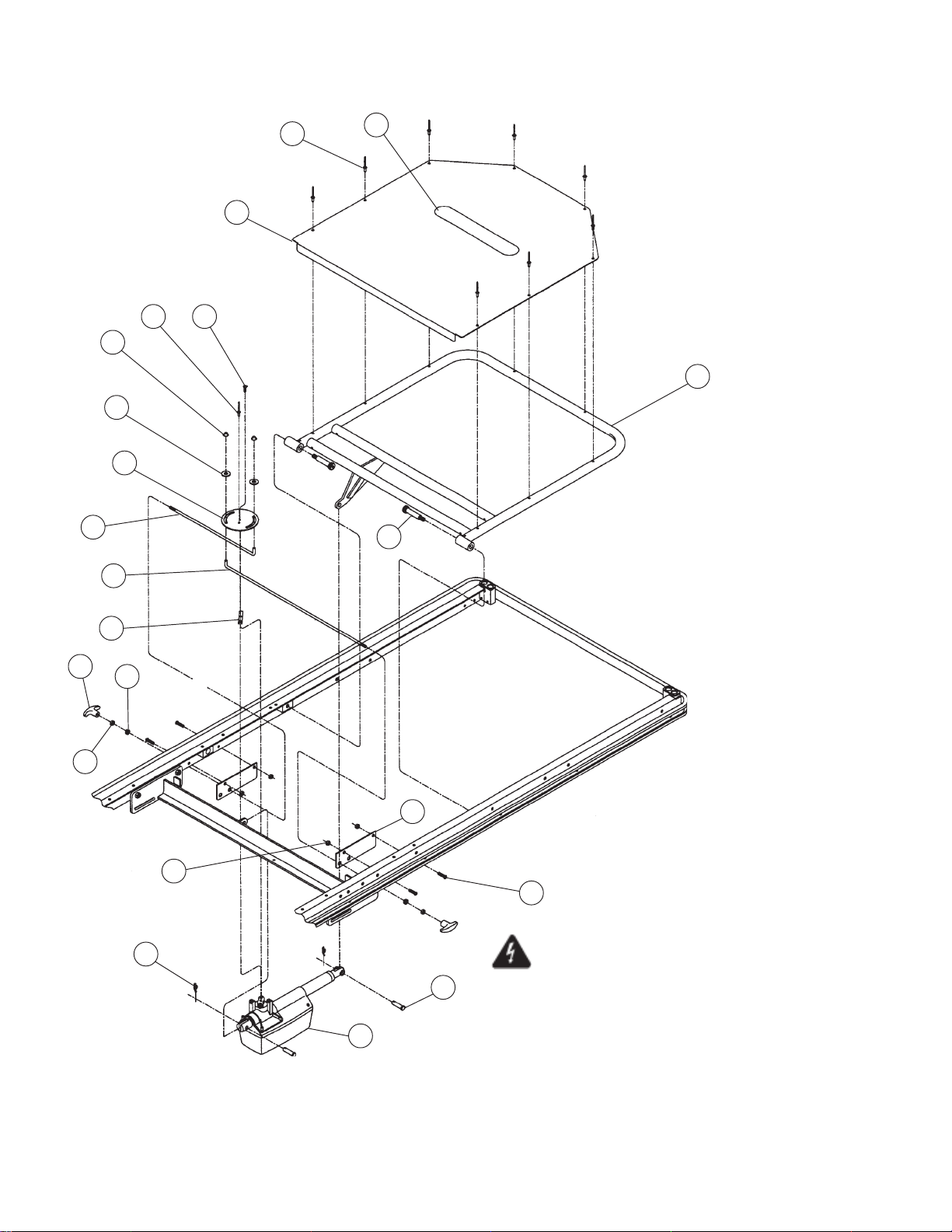
4
17
18
3
1118
5
7
1
14
15
6
12
13
16
20
10
2
19
21
Important Note: To reduce the risk of electric
9
shock, do not remove the cover.
Unit is to be serviced by qualified personnel only.
8
For detailed plug locations, see Figures 7-18 & 7-19.
For detailed label locations, see Figures 7-20.
Figure 7-13. HMC Fowler Assembly
7-28
069389 Operator Manual Recommended Replacement Parts
Page 54
FIG. &
ITEM
NO.
7-13- HMC FOWLER ASSEMBLY ....................................................... X
*1 075425 Fowler Frame-Electric / Wide ...................................................... 1
2 062037 Shoulder Bolt, 1/2 x 2 .................................................................. 2
*3 065879 Fowler Cover Sheet/Wide ............................................................ 1
4 075443 NUT, Cap, 1/4"............................................................................. 2
5 075437 PLATE, Actuator .......................................................................... 1
6 075440 ROD, Quick Drop Release, Short ................................................ 1
7 031212 HOOK, Velcro .............................................................................. 1
8 068985 ACTUATOR, Fowler Backrest ..................................................... 1
9 075627 PIN, Gas Spring Hinge................................................................. 2
10 065258 CLIP, Rue 3/8 .............................................................................. 2
11 075444 SCREW, Slotted Pan Head, M5 x 20MM .................................... 1
12 075439 ROD, Quick Drop Release, Long................................................. 1
13 075441 SPACER ...................................................................................... 1
14 055215 KNOB, Pull ................................................................................... 2
15 031054 NUT, Free Thread, 1/4-20 ........................................................... 2
16 061336 BEARING, Nylon.......................................................................... 2
17 065688 WASHER, Nylon 5/16"................................................................. 2
18 000794 RIVET, Pop, Aluminum, 3/16"...................................................... 9
19 P75438 PLATE, Quick Drop Support ........................................................ 2
20 031055 NUT, Lock, 1/4-20........................................................................ 4
21 031327 SCREW, Button Head Socket, 1/4-20 x 1.0" Long ...................... 4
PART
NUMBER
S
V
C
DESCRIPTION
UNITS PER
ASSEMBLY
NOTE: The “O” suffix on the part numbers marked with an
“ * ” designate part numbers for the chrome/stainless units
(Model 4E2 DPA-SS). For powder coated units (Model 4E2
DPA-PC), the “O” suffix should be relace with a “P” suffix.
(Example: Item 1 for a powder coated unit 4E2 DPA-PC,
would become P75425).
7-29
Recommended Replacement Parts Operator Manual 069389
Page 55
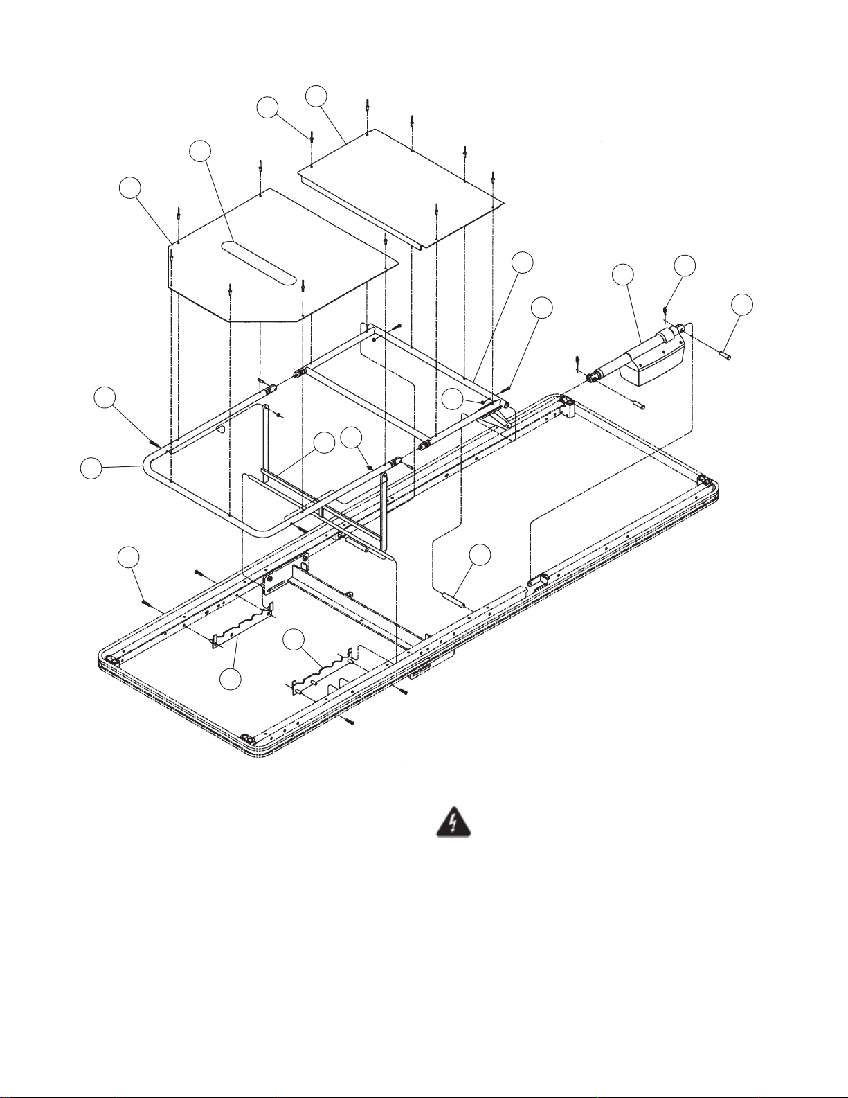
8
7
4
3
1
18
6
17
3
2
16
14
19
10
11
13
12
15
Important Note: To reduce the risk of electric
shock, do not remove the cover.
Unit is to be serviced by qualified personnel only.
For detailed plug locations, see Figures 7-18 & 7-19.
For detailed label locations, see Figures 7-20.
Figure 7-14. HMC Leg Section Assembly
7-30
069389 Operator Manual Recommended Replacement Parts
Page 56
FIG. &
ITEM
NO.
PART
NUMBER
S
V
DESCRIPTION
C
7-14- HMC LEG SECTION ASSEMBLY............................................... X
1 P65626 WELDMENT, Knee Frame, Extra Wide ....................................... 1
2 P65629 ASSEMBLY, Foot Frame, Extra Wide ......................................... 1
3 062254 SUPPORT, Kneeflex Foot, Extra Wide........................................ 1
4 P62261 SHEET, Foot Section Cover , Extra Wide ................................... 1
5 P33050 SHEET, Knee Section Cover, Extra Wide ................................... 1
6 062128 SCREW, Button Head Socket, 1/4-20 x 1-1/4" long .................... 2
7 031212 HOOK, Velcro .............................................................................. 1
8 000794 RIVET, Cherry, 3/16" x .45" ......................................................... 12
9 031312 PIN, Spring, 1/4" x 3/4" ................................................................ 2
10 062209 SHAFT, Cross Bar ....................................................................... 2
11 068986 ACTUATOR, Leg Rest ................................................................. 1
12 075627 PIN, Gas Spring Hinge................................................................. 2
13 065258 CLIP, Rue 3/8 .............................................................................. 2
14 065060 PLATE, Ratchet, Right................................................................. 1
15 065061 PLATE, Ratchet, Left. .................................................................. 1
16 031327 SCREW, Button Head Socket, 1/4-20 x 1.0" Long ...................... 4
17 031055 NUT, Lock, 1/4-20........................................................................ 2
18 075502 SCREW, Phillips Pan Head, #10-24 x 1-1/8" Long ..................... 2
19 031421 NUT, Lock, #10-24....................................................................... 2
UNITS PER
ASSEMBLY
7-31
Recommended Replacement Parts Operator Manual 069389
Page 57
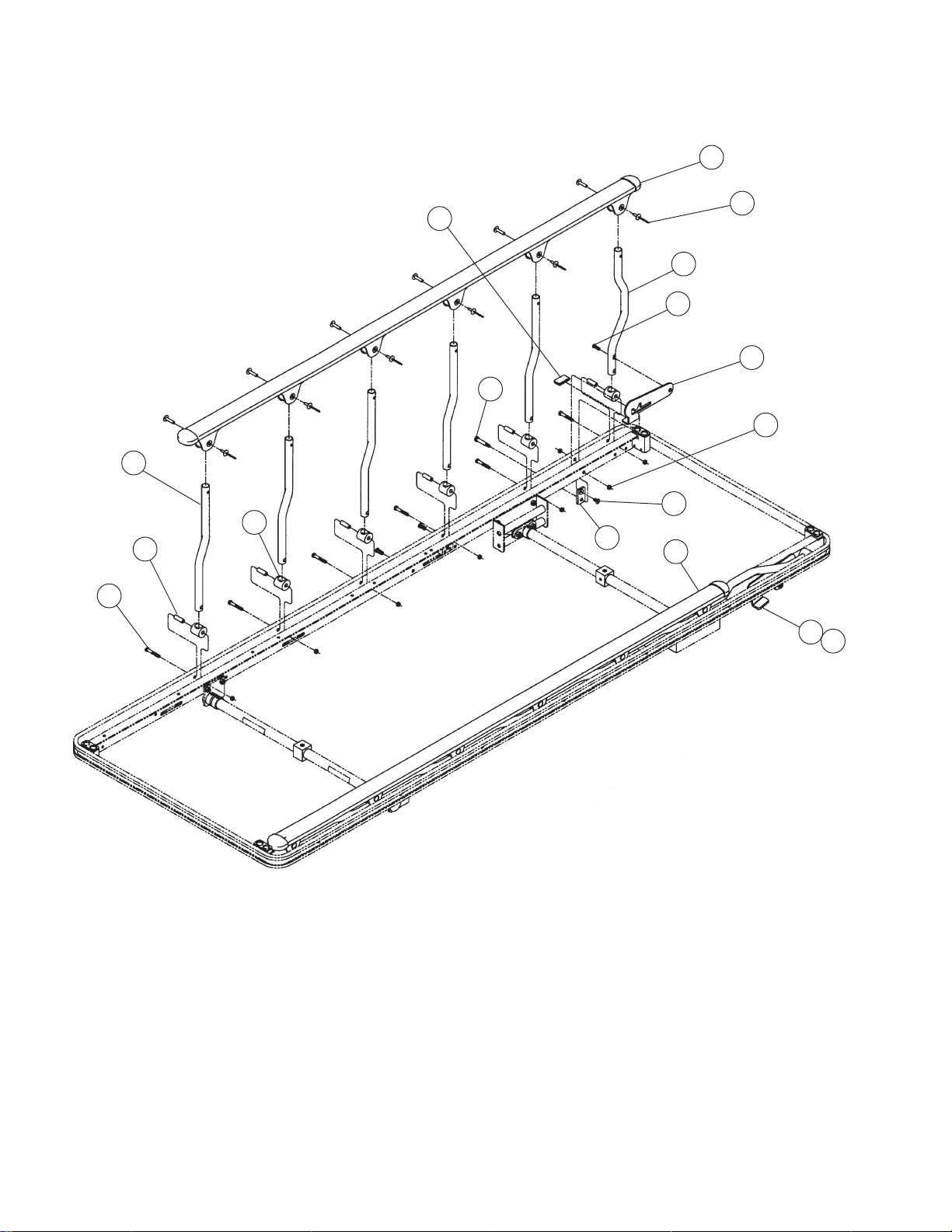
1
13
10
9
18
5
15
6
7
8
14
2
4
11
17
12
13
NOTE: Only one side of rail is shown for
clarity. The bill of material reflects parts
required for a complete unit.
Figure 7-15. Retracto Rail Assembly
7-32
069389 Operator Manual Recommended Replacement Parts
Page 58
FIG. &
ITEM
NO.
PART
NUMBER
S
V
DESCRIPTION
C
7-15- RETRACTO RAIL ASSEMBLY................................................... X
1 075057 ASSEMBLY, Top Cap, Left.......................................................... 1
2 075056 ASSEMBLY, Top Cap, Right ....................................................... 1
3 068886 RIVET, Cherry, Female End ........................................................ 12
4 068886 RIVET, Cherry, Male End ............................................................ 12
5 068882 LEG, Offset .................................................................................. 10
6 035137 ROCKER...................................................................................... 12
7 035138 SPACER ...................................................................................... 12
8 035122 SCREW, Hex Head Cap, 1/4-20 x 1- 5/8" Long .......................... 12
9 062038 SCREW, Button Head Socket, 1/4-20 x 3/4" Long ...................... 2
10 068833 LEG, Lock .................................................................................... 2
11 065432 PLATE, Lock, Left ........................................................................ 1
12 065433 PLATE, Lock, Right...................................................................... 1
13 075269 CAP, Red Vinyl ............................................................................ 2
14 068198 SUPPORT, Retracto Rail Plate.................................................... 2
15 031325 SCREW, Flat Head Socket, 1/4-20 x 1/2" Long .......................... 2
16 066617 BOLT, Shoulder, 5/16" x 1-1/4" long............................................ 2
17 031055 NUT, Lock, 1/4-20........................................................................ 16
UNITS PER
ASSEMBLY
7-33
Recommended Replacement Parts Operator Manual 069389
Page 59
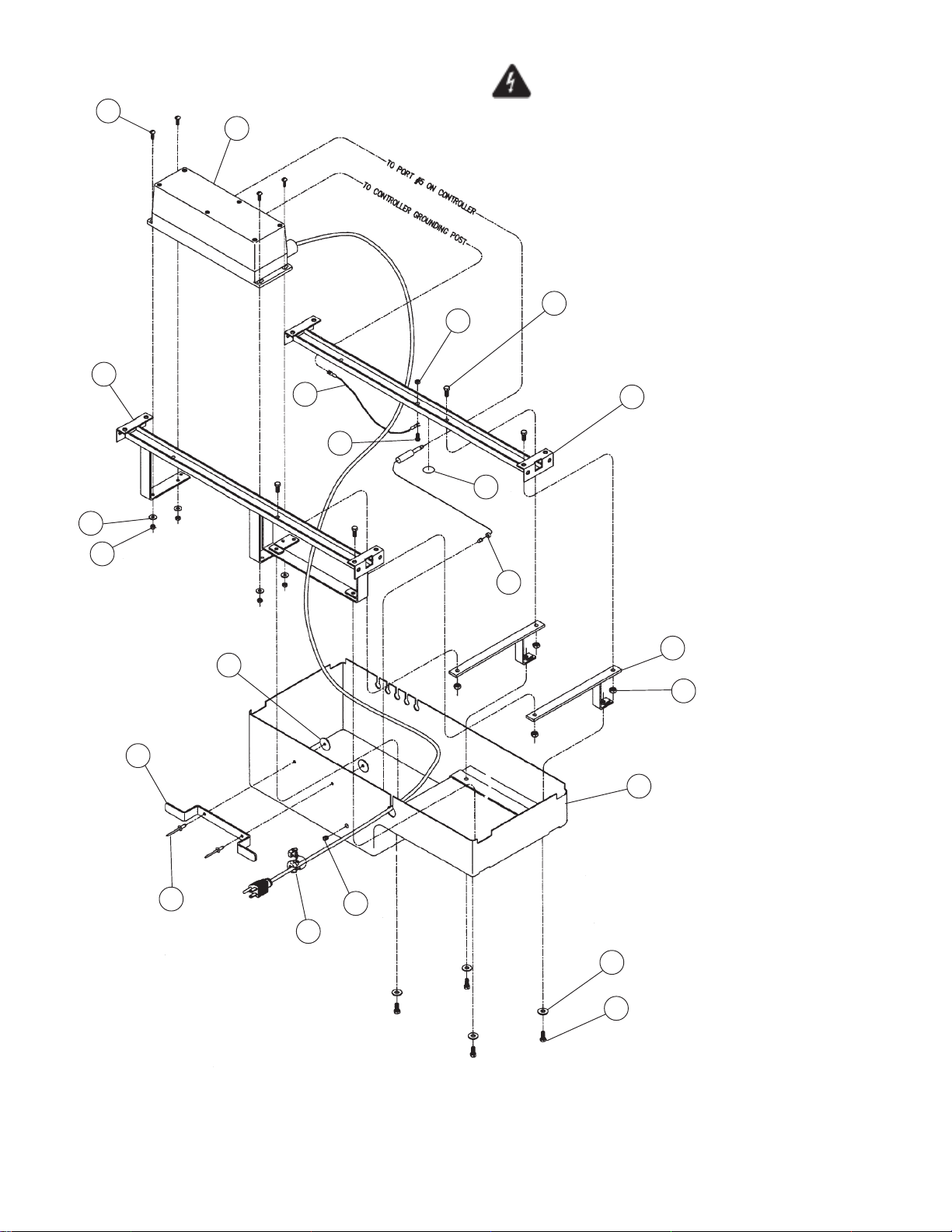
Important Note: To reduce the risk of electric
3
2
shock, do not remove the cover.
Unit is to be serviced by qualified personnel only.
For detailed plug locations, see Figures 7-18 & 7-19.
For detailed label locations, see Figures 7-20.
7
5
1
6
11
12
4
17
5
10
18
19
9
15
12
16
14
10
8
7
Figure 7-16. 4E2/4D2 – HMC Controller Assembly (After 5/1/00)
7-34
069389 Operator Manual Recommended Replacement Parts
Page 60
FIG. &
ITEM
NO.
PART
NUMBER
S
V
DESCRIPTION
C
7-16- 4E2/4D2 – HMC CONTROLLER ASSEMBLY (AFTER 5/1/00) . X
1 065135 HANGER, Controller, Rear E.W. ................................................. 1
2 075044 CONTROLLER, CB -14, 120 VAC, 4E2 ...................................... 1
075718 CONTROLLER, CB -14, 230 VAC, 4D2 ...................................... 1
3 061159 SCREW, Truss Head Machine, #10 24 x 5/8" Long .................... 4
4 031074 WASHER, Flat, 3/16" ................................................................... 6
5 031421 NUT, Lock, #10-24....................................................................... 5
6 076125 WIRE, Controller Ground ............................................................. 1
7 068786 SCREW, Hex Head Cap, 1/4-20 x 5/8" Long .............................. 8
8 031364 WASHER, Flat, 1/4" ..................................................................... 4
9 031055 NUT, Lock, 1/4-20........................................................................ 4
10 075749 ASSEMBLY, LED Wire ................................................................ 1
11 031000 SCREW, Hex Head Cap, #10-24 x 1/2" Long ............................. 1
12 076132 LABEL, Ground Symbol............................................................... 1
13 075077 COVER, Controller....................................................................... 1
14 068982 RELIEF, Strain ............................................................................. 1
15 076123 BRACKET, Cord Wrap................................................................. 1
16 000794 RIVET, 3/16" ................................................................................ 2
17 000703 HANGER, Controller, Front E.W.................................................. 1
18 075705 BRACKET, Cord Reel.................................................................. 2
19 000787 WASHER, 3/16" Large O.D. ........................................................ 2
UNITS PER
ASSEMBLY
7-35
Recommended Replacement Parts Operator Manual 069389
Page 61
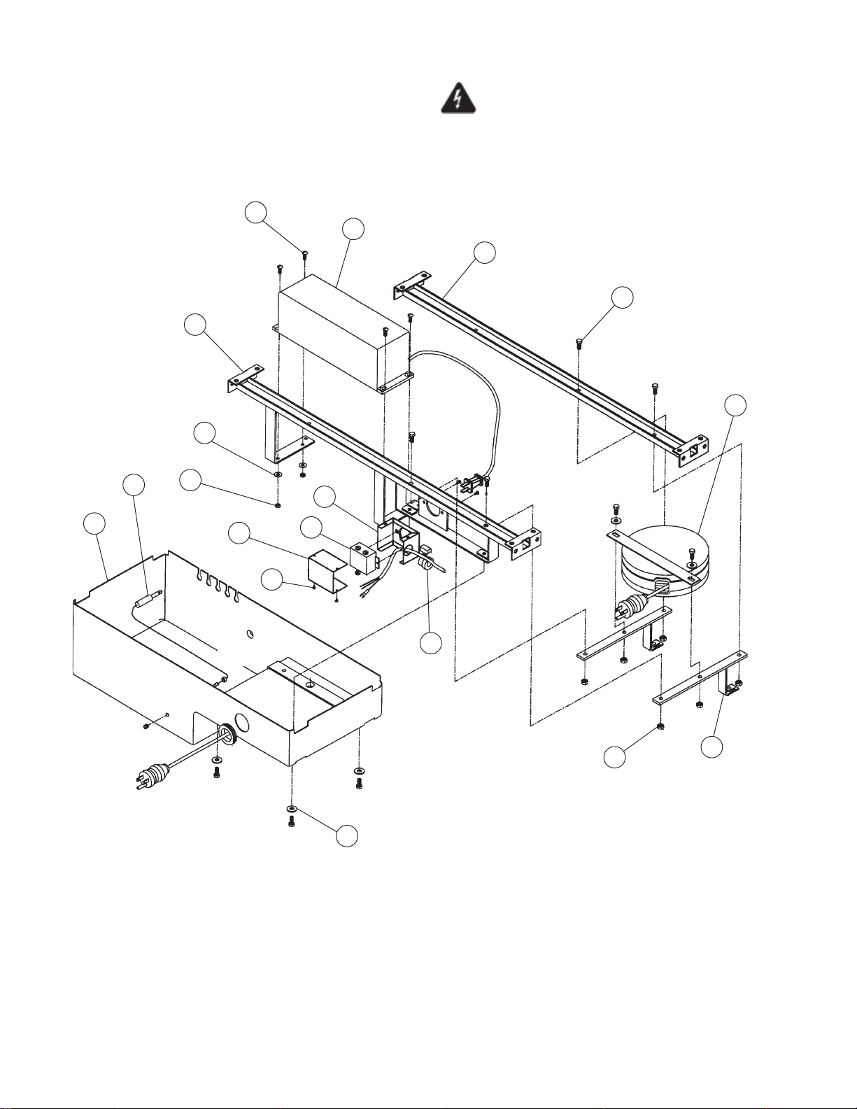
Important Note: To reduce the risk of electric
shock, do not remove the cover.
Unit is to be serviced by qualified personnel only.
For detailed plug locations, see Figures 7-18 & 7-19.
For detailed label locations, see Figures 7-20.
2
1
4
3
8
5
18
15
20
17
11
12
10
9
13
6
16
7
Figure 7-17. 4E2/4D2 – HMC Controller Assembly (Before 5/1/00)
7-36
069389 Operator Manual Recommended Replacement Parts
Page 62
FIG. &
ITEM
NO.
PART
NUMBER
S
V
DESCRIPTION
C
7-17- 4E2/4D2 – HMC CONTROLLER ASSEMBLY (BEFORE 5/1/00) X
1 068962 CONTROLLER, CB-10, 120 VAC, 4E2 ....................................... 1
075044 CONTROLLER, CB-14, 120 VAC, 4E2 (After 5/1/00) ................. 1
075467 CONTROLLER, CB-10, 230 VAC, 4D2 ....................................... 1
075718 CONTROLLER, CB-14, 230 VAC, 4D2 (After 5/1/00) ................. 1
2 061159 SCREW, Truss Head Machine, #10 24 x 5/8" Long .................... 4
3 068786 SCREW, Hex Head Cap, 1/4-20 x 5/8" Long .............................. 10
4 075703 HANGER, Controller, Front XW ................................................... 1
5 068966 REEL, Cord Reel ......................................................................... 1
6 031055 NUT, Lock, 1/4-20........................................................................ 6
7 075705 WELDMENT, Cord Reel Bracket ................................................. 2
8 075702 HANGER, Controller, Rear-XW ................................................... 1
9 068979 BASE, Junction Box Base ........................................................... 1
10 068976 RECEPTACLE, Hospital Grade ................................................... 1
11 068980 COVER, Junction Box Cover ....................................................... 1
12 031097 SCREW, Sheet Metal, #6 ............................................................ 2
13 068982 RELIEF, Strain ............................................................................. 1
14 SCREW, #8 32 (Furnished with Receptacle) .............................. 2
15 075077 COVER, Controller Cover ............................................................ 1
16 031364 WASHER, Flat, 1/4" ..................................................................... 6
17 031421 NUT, Lock, #10-24....................................................................... 4
18 031074 WASHER, Flat, 3/16" ................................................................... 4
19 068981 GROMMET .................................................................................. 1
20 075749 ASSEMBLY, Cable LED .............................................................. 1
UNITS PER
ASSEMBLY
7-37
Recommended Replacement Parts Operator Manual 069389
Page 63
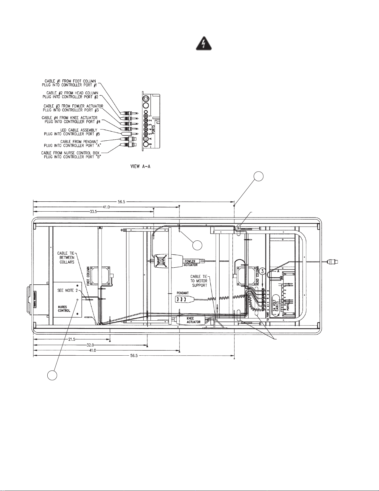
Important Note: To reduce the risk of electric
shock, do not remove the cover.
Unit is to be serviced by qualified personnel only.
For detailed label locations, see Figures 7-20.
1
See Note 3
2
See Note 3
1
Notes:
1. Wrap excess cable and tie with cable tie (2) 5 each. Place
bundles on top of controller before attaching top cover.
2. Cable tie nurse control cable with enough slack to permit
full movement of slide.
3. Allow 1" of slack in cables for Trendelenburg movement
on both sides.
Figure 7-18. HMC Plug and Wiring Diagram (After 5/1/00)
7-38
069389 Operator Manual Recommended Replacement Parts
Page 64
FIG. &
ITEM
NO.
PART
NUMBER
S
V
DESCRIPTION
C
7-18- HMC PLUG AND WIRING DIAGRAM (AFTER 5/1/00) .............. X
1 068864 RELIEF, Strain ............................................................................. 6
2 065403 TIE, Cable, (Large) ...................................................................... 20
3 063031 BUTTON ...................................................................................... 7
UNITS PER
ASSEMBLY
7-39
Recommended Replacement Parts Operator Manual 069389
Page 65
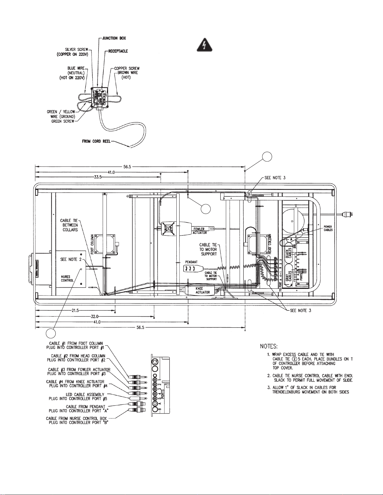
Important Note: To reduce the risk of electric
shock, do not remove the cover.
Unit is to be serviced by qualified personnel only.
For detailed label locations, see Figures 7-20.
1
2
1
Figure 7-19. HMC Plug and Wiring Diagram (Before 5/1/00)
7-40
069389 Operator Manual Recommended Replacement Parts
Page 66
FIG. &
ITEM
NO.
PART
NUMBER
S
V
DESCRIPTION
C
7-19- HMC PLUG AND WIRING DIAGRAM (BEFORE 5/1/00) ........... X
1 063031 BUTTON ...................................................................................... 7
2 065403 TIE, Cable, (Large) ...................................................................... 20
3 068864 RELIEF, Strain ............................................................................. 6
UNITS PER
ASSEMBLY
7-41
Recommended Replacement Parts Operator Manual 069389
Page 67
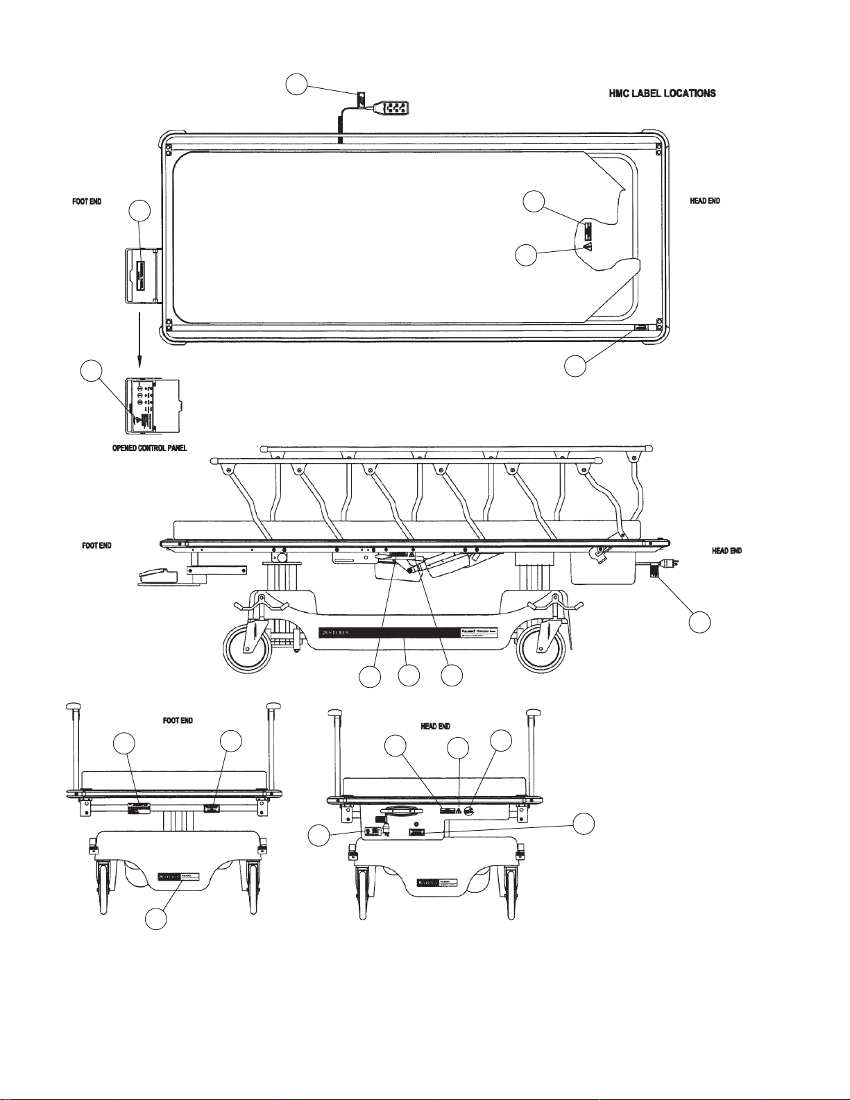
13
16
11
3
6
14
8
16
6
Both Sides
7
17
Both Sides
4
2
Both Sides
15
18
12
1
Both Sides
3
Figure 7-20. 4E2/4D2 – HMC Label Locations
7-42
069389 Operator Manual Recommended Replacement Parts
Page 68
FIG. &
ITEM
NO.
PART
NUMBER
S
V
DESCRIPTION
C
7-20- 4E2 – HMC LABEL LOCATIONS ............................................... X
4D2 – HMC LABEL LOCATIONS ............................................... X
1 075836 LABEL, Side-Electric Stretcher .................................................... 2 2
2 075831 LABEL, Base End ........................................................................ 2 2
3 068855 LABEL, Electric Service ............................................................... 2 2
4 076127 LABEL, Serial Number, 110V Electric ......................................... 1 –
075475 LABEL, Serial Number, 230V Electric ......................................... – 1
5 031458 OVERLAY, Clear Mylar................................................................ 1 1
6 075478 LABEL, Dangerous Voltage ......................................................... 2 2
7 075484 LABEL, Unplug Before Servicing ................................................. 1 1
8 055025 LABEL, Hospital Grade Receptacle............................................. 1 –
9 066716 LABEL, Rail Release ................................................................... 4 4
10 066717 LABEL, Rail Operation ................................................................. 2 2
11 075035 LABEL, Control Pane ................................................................... 1 1
12 075040 LABEL, Emergency Release ....................................................... 2 2
13 075489 LABEL, Pendant .......................................................................... 1 1
14 075589 LABEL, Maximum Weight, 625 Lbs. ............................................ 1 1
15 063022 LABEL, Service ............................................................................ 1 1
16 075479 LABEL, Hazardous Area.............................................................. 5 5
17 075748 LABEL, Low Battery..................................................................... 1 1
18 061815 LABEL, ETL Listing...................................................................... 1 –
UNITS PER
ASSEMBLY
7-43
Recommended Replacement Parts Operator Manual 069389
Page 69
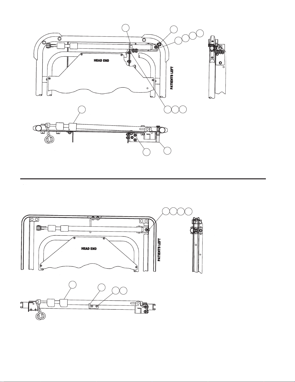
12
11
7
6
5
2
4
9
Accessory Number: 075590-00 I.V. Rod, Airglide Rail Tops, Pat Left
Accessory Number: 075591-00 I.V. Rod, Airglide Rail Tops, Pat Right
Accessory Number: 075543-00 I.V. Rod, Retracto Rail Tops
2 10
8
2 5
11
NOTE: I.V. Rod is shown mounted on
patient’s left, which is standard. The
I.V. rod can be mounted on the patient’s
right by bolting to the other side angle
using Item 13 in place of Item 8 and
Item 14 in place of Item 9.
6 7
4
3
1
2
NOTE: I.V. Rod is shown mounted
on patient’s left, which is standard.
The I.V. rod can be mounted on the
patient’s right by bolting to the other
side angle.
Figure 7-21. I.V. Rod Assembly (After 10/1/98)
7-44
069389 Operator Manual Recommended Replacement Parts
Page 70
FIG. &
ITEM
NO.
PART
NUMBER
S
V
DESCRIPTION
C
7-21- 075590 00 I.V. ROD ASSEMBLY, AIRGLIDE RAIL TOP, PAT LEFT
(AFTER 10/1/98)......................................................................... X
075591 00 I.V. ROD ASSEMBLY, AIRGLIDE RAIL TOP, PAT RIGHT
(AFTER 10/1/98)......................................................................... X
075543 I.V. ROD ASSEMBLY, RETRACTO RAIL TOP (AFTER 10/1/98) X
1 062038 SCREW, Button Head Cap, 1/4 -20 x 5/8" Long ......................... – 2
2 031055 NUT, Lock, 1/4 -20....................................................................... 7 4
3 075568 SUPPORT, Bracket I.V. Rod Support.......................................... – 1
4 075545 ASSEMBLY, Trigger Style I.V. Rod ............................................. 1 1
5 031137 SCREW, Hex Head Cap, 1/4 -20 x 3/4" Long ............................. 2 2
6 031364 WASHER, Flat, 1/4" ..................................................................... 2 2
7 030923 WASHER, Lock, 3/8" ................................................................... 2 2
8 075570 WELDMENT, I.V. Rod Mounting Bracket, Right .......................... 1 –
9 075573 BRACKET, I.V. Rod Attachment-Right ........................................ 1 –
10 031076 WASHER, Flat, 5/16" ................................................................... 5 –
11 031033 SCREW, Flat Socket Head Cap, 5/16 -18 x 1.0" Long................ 1 –
12 061592 GROMMET, Self Adhesive .......................................................... 1 –
13 075575 WELDMENT, , I.V. Rod Mounting Bracket, Left .......................... – –
14 075576 BRACKET, I.V. Rod Attachment, Left.......................................... – –
UNITS PER
ASSEMBLY
7-45
Recommended Replacement Parts Operator Manual 069389
Page 71
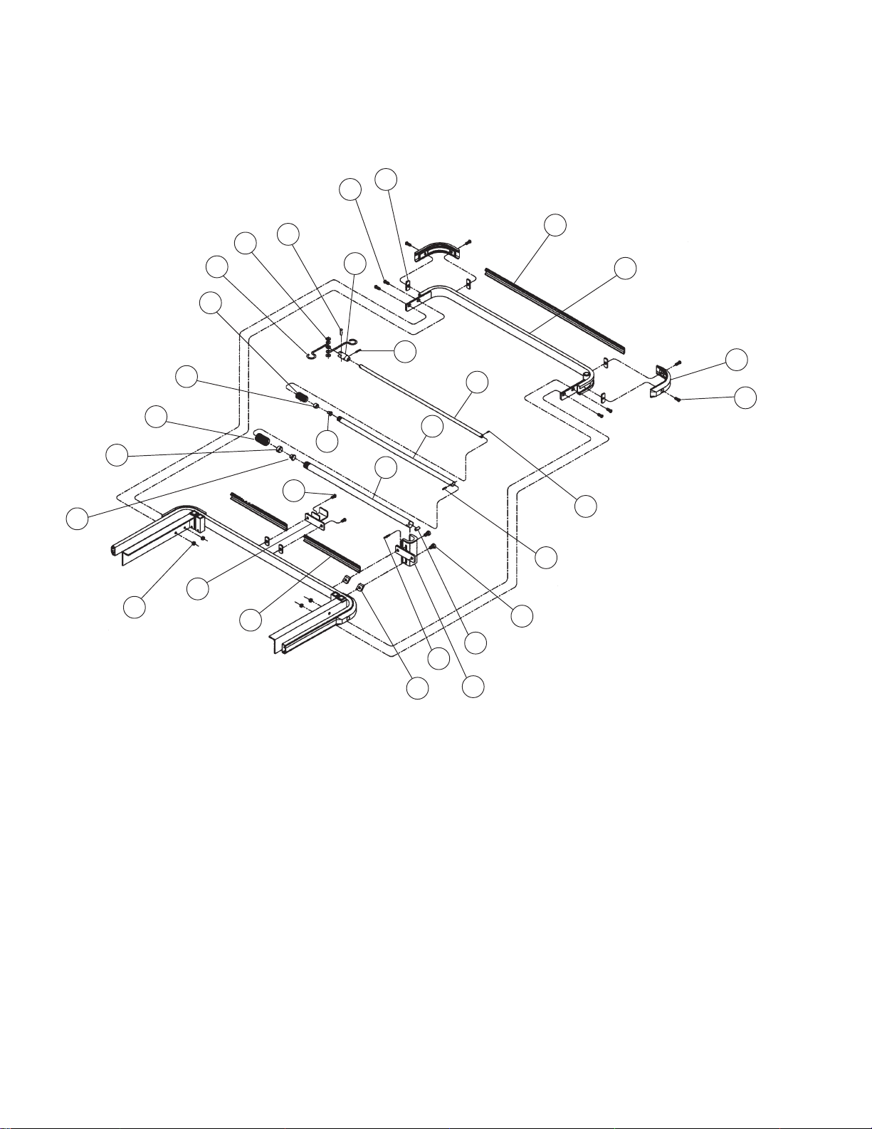
26
20
17
16
10
9
5
4
7
22
27
18
14
15
11
5
12
2
21
28
19
3
29
25
30
26
13
8
24
23
1
3 section mounted I.V. rod assemblies
Figure 7-22. HMC I.V. Rod Assembly (Before 10/1/98)
7-46
069389 Operator Manual Recommended Replacement Parts
Page 72
FIG. &
ITEM
NO.
7-22- 066021 HMC I.V. ROD ASSEMBLY (BEFORE 10/1/98) ......................... X
1 066002 ASSEMBLY, Hinge ...................................................................... 1
2 066012 TUBE, Outside ............................................................................. 1
3 031438 PIN, Spring, 3/16" x 1-1/4" ........................................................... 1
4 066014 BUSHING, Large Screw Collar Squeeze..................................... 1
5 066013 COLLAR, Large Screw ................................................................ 1
6 066016 TUBE, Large Slide ....................................................................... 1
7 066015 GLIDE, Outside Cap .................................................................... 1
8 031314 PIN, Spring, 3/16" x 3/4" .............................................................. 1
9 030209 BUSHING, Screw Collar Squeeze ............................................... 1
10 030207 Screw Collar................................................................................. 1
11 066017 TUBE, Small Slide ....................................................................... 1
12 030176 GLIDE, Inside Cap ....................................................................... 1
13 065605 PIN, Spring, 1/8" x 1/2" ................................................................ 1
14 062328 CAP, Top Ear ............................................................................... 1
15 031110 PIN, Spring, 3/16" x 7/8" .............................................................. 1
16 062326 HOOK, Bag .................................................................................. 2
17 031100 5/16 ID x 3/4 OD WASHER, Nylon .............................................. 3
18 062329 RIVET, Tubular Rivet ................................................................... 1
19 066734 SPACER, Pin Spacer................................................................... 1
20 031455 NUT, Weldment, 1/4-20 ............................................................... 6
21 031325 SCREW, Button Head Cap, 1/4-20 x 1/2" Long .......................... 2
22 066006 ASSEMBLY, I.V. Rod Stop .......................................................... 1
23 066018 NUT, Channel, 5/16-28 ................................................................ 2
24 066022 SCREW, Hex Head Cap, 5/16-28 x 1/2" Long ............................ 2
25 066023 * WELDMENT, Bumper Guard ....................................................... 1
26 061195 SCREW, Button Head Socket, 1/4-20 x 5/8" Long ...................... 8
27 031055 NUT, Lock, 1/4-20........................................................................ 4
28 068152 EXTRUSION, Short Bumper, Gray .............................................. 2
29 13193D EXTRUSION, Short Bumper, Red ............................................... 2
30 13193R EXTRUSION, Long Bumper, Red................................................ 1
PART
NUMBER
13193H EXTRUSION, Short Bumper, Blue............................................... 2
13193X EXTRUSION, Short Bumper, Green............................................ 2
068153 EXTRUSION, Long Bumper, Gray............................................... 1
13193S EXTRUSION, Long Bumper, Blue ............................................... 1
13193T EXTRUSION, Long Bumper, Green ............................................ 1
067958 BUMPER, Corner......................................................................... 2
S
V
C
DESCRIPTION
UNITS PER
ASSEMBLY
NOTE: The “O” suffix on the part numbers marked with an
“ * ” designate part numbers for the chrome/stainless units
(Model 4E2 DPA-SS). For powder coated units (Model 4E2
DPA-PC), the “O” suffix should be relace with a “P” suffix.
(Example: Item 25 for a powder coated unit 4E2 DPA-PC,
would become P66023).
7-47
Recommended Replacement Parts Operator Manual 069389
Page 73
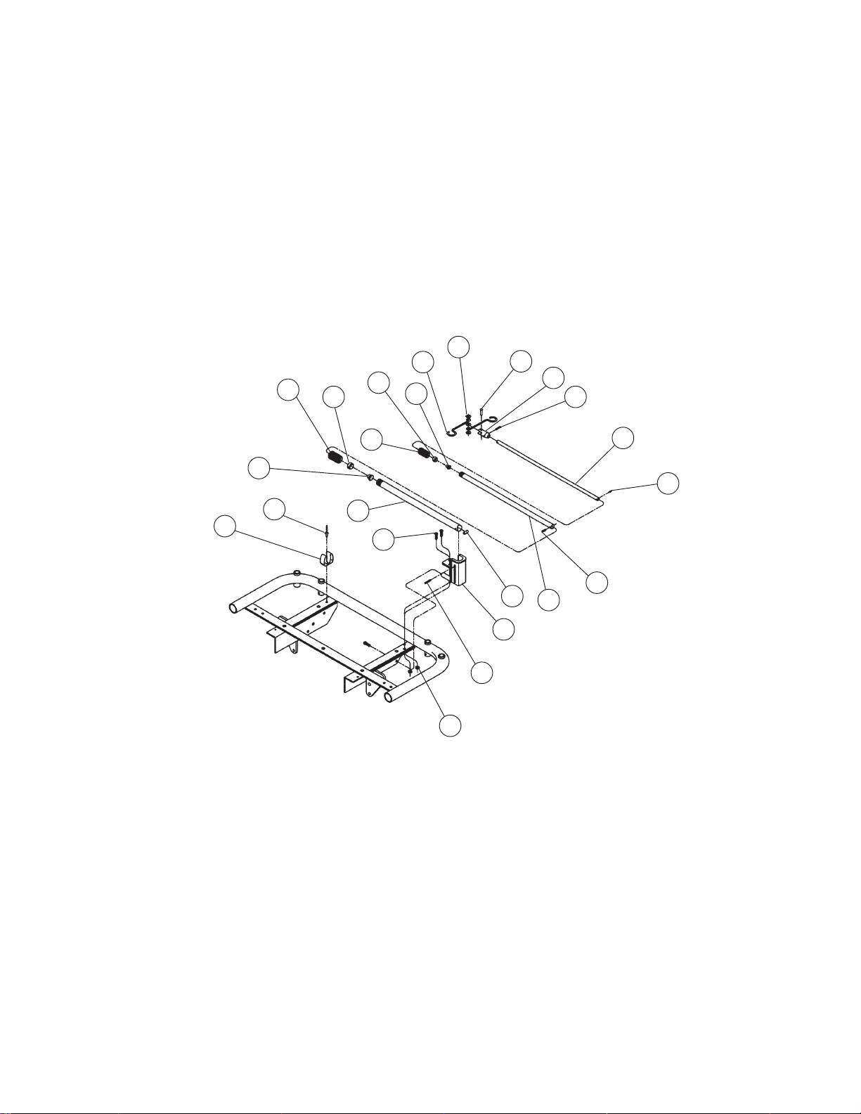
17
16
5
4
9
12
18
14
15
22
10
7
23
2
20
19
6
1
3
21
11
13
18
Figure 7-23. DPA I.V. Rod Assembly (Before 10/1/98)
7-48
069389 Operator Manual Recommended Replacement Parts
Page 74
FIG. &
ITEM
NO.
PART
NUMBER
S
V
DESCRIPTION
C
7-23- 066725 DPA I.V. ROD ASSEMBLY (BEFORE 10/1/98).......................... X
1 066727 ASSEMBLY, I.V. Rod Support and Mount ................................... 1
2 066731 TUBE, Short Outside ................................................................... 1
3 031438 PIN, Spring, 3/16" x 1-1/4" ........................................................... 1
4 066014 BUSHING, Large Screw Collar Squeeze..................................... 1
5 066013 COLLAR, Large Screw ................................................................ 1
6 066732 TUBE, Short Slide ........................................................................ 1
7 066015 GLIDE, Outside Cap .................................................................... 1
8 031314 PIN, Spring, 3/16" x 3/4" .............................................................. 1
9 030209 BUSHING, Screw Collar Squeeze ............................................... 1
10 030207 COLLAR, Screw........................................................................... 1
11 066733 TUBE, Short Inside ...................................................................... 1
12 030176 GLIDE, Inside Cap ....................................................................... 1
13 065605 PIN, Spring, 1/8" x 1/2" ................................................................ 1
14 062328 CAP, Top Ear ............................................................................... 1
15 031110 PIN, Spring, 3/16" x 7/8" .............................................................. 1
16 062327 HOOK, Bag .................................................................................. 2
17 031100 WASHER, Nylon, 5/16" I.D. x 3/4" O.D........................................ 3
18 062329 RIVET, Tubular ............................................................................ 1
19 066734 SPACER, I.V. Rod Pin ................................................................. 1
20 062038 SCREW, Button Head Socket, 1/4-20 x 3/4" long ....................... 3
21 031055 NUT, Lock, 1/4-20........................................................................ 2
22 062008 CLIP, Broom ................................................................................ 1
23 000794 RIVET, Pop, 3/16" x 1/2".............................................................. 1
UNITS PER
ASSEMBLY
7-49
Recommended Replacement Parts Operator Manual 069389
Page 75
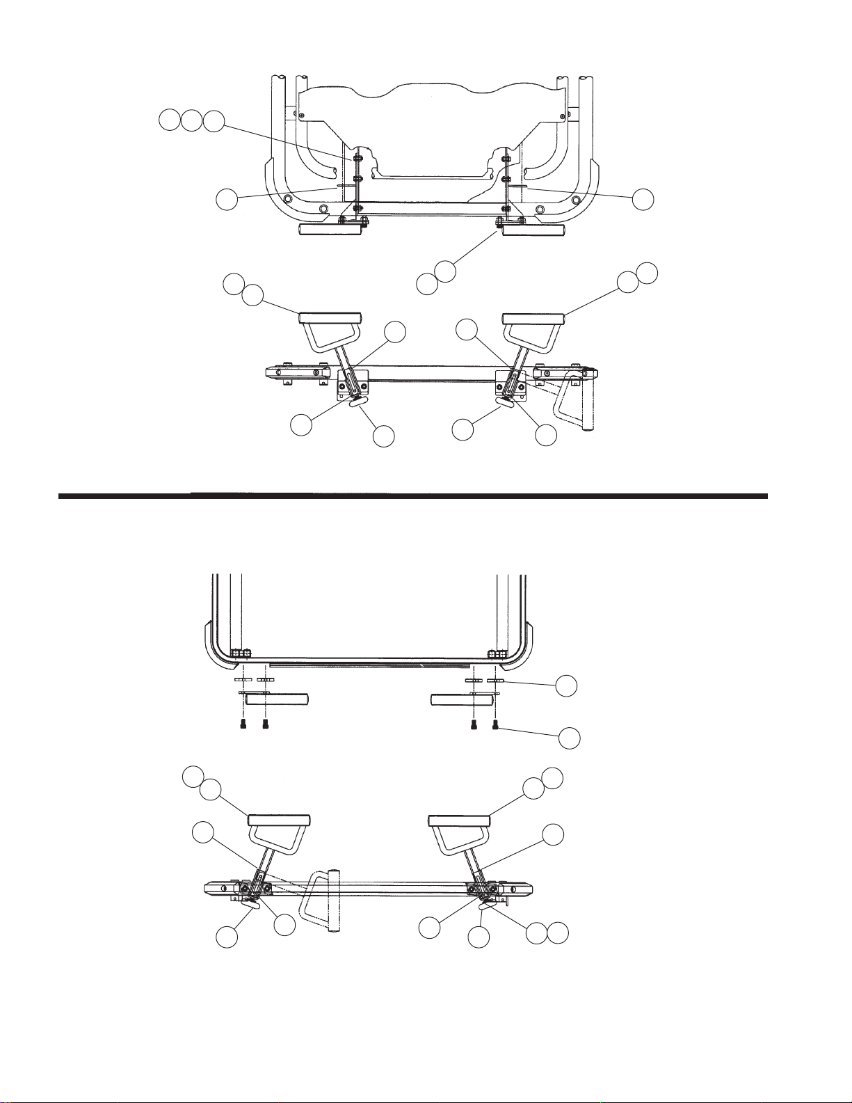
19
18
5
1615
3
2
6
7
8
10
13
Accessory Number: 075665-00 Push Handles – Airglide Tops
Accessory Number: 075656-00 Push Handles – Retracto Rail Tops
3
1
4
8
7
12
11
3
1
4
8
7
7
8
3
2
6
10
9
Figure 7-24. Push Bar Assembly After 6/1/99)
7-50
069389 Operator Manual Recommended Replacement Parts
Page 76
FIG. &
ITEM
NO.
7-24- 075665 00 PUSH BAR ASSEMBLY, AIRGLIDE RAIL TOP (AFTER 6/1/99) X
1 065631 ASSEMBLY, Push Handle A........................................................ 1 1
2 075642 ASSEMBLY, Push Handle B........................................................ 1 1
3 075637 • WELDMENT, Push Handle ....................................................... 1 1
4 075633 • BRACKET, Hinge, A .................................................................. 1 1
5 031076 • WASHER, Flat, USS, 1/4" ......................................................... 8 –
6 075734 • BRACKET, Hinge, B .................................................................. 1 1
7 031118 • PIN, Spring, 3/16" x 1" ............................................................... 1 1
8 075643 • BUMPER, 1-3/4 Diameter.......................................................... 1 1
9 031364 • WASHER, Flat, 1/4"................................................................... 2 1
10 031055 • NUT, Lock, 1/4-20 ..................................................................... 1 1
11 075657 SCREW, Socket Head Cap, 5/16-18 x 1/2" Long ........................ 4 1
12 066018 NUT, Channel, 5/16-18 ................................................................ 4 1
13 035192 SCREW, Socket Head Cap, 5/16-18 X 3/4" Long ....................... 4 1
14 031956 NUT, Lock, 15/16"........................................................................ 4 1
15 P75646 WELDMENT, Bracket A ............................................................... 1 1
16 P75651 WELDMENT, Bracket B ............................................................... 1 1
17 P75652 BARS, Connecting Bar Push, E.W. ............................................. 1 1
18 068786 SCREW, Hex Head Cap, 1/4-20 x 5/8" Long .............................. 8 1
PART
NUMBER
075656 00 PUSH BAR ASSEMBLY, RETRACTO RAIL TOP
S
V
C
(AFTER 6/1/99)........................................................................... X
DESCRIPTION
UNITS PER
ASSEMBLY
Items 3-10 are included in Items 1 and 2.
7-51
Recommended Replacement Parts Operator Manual 069389
Page 77
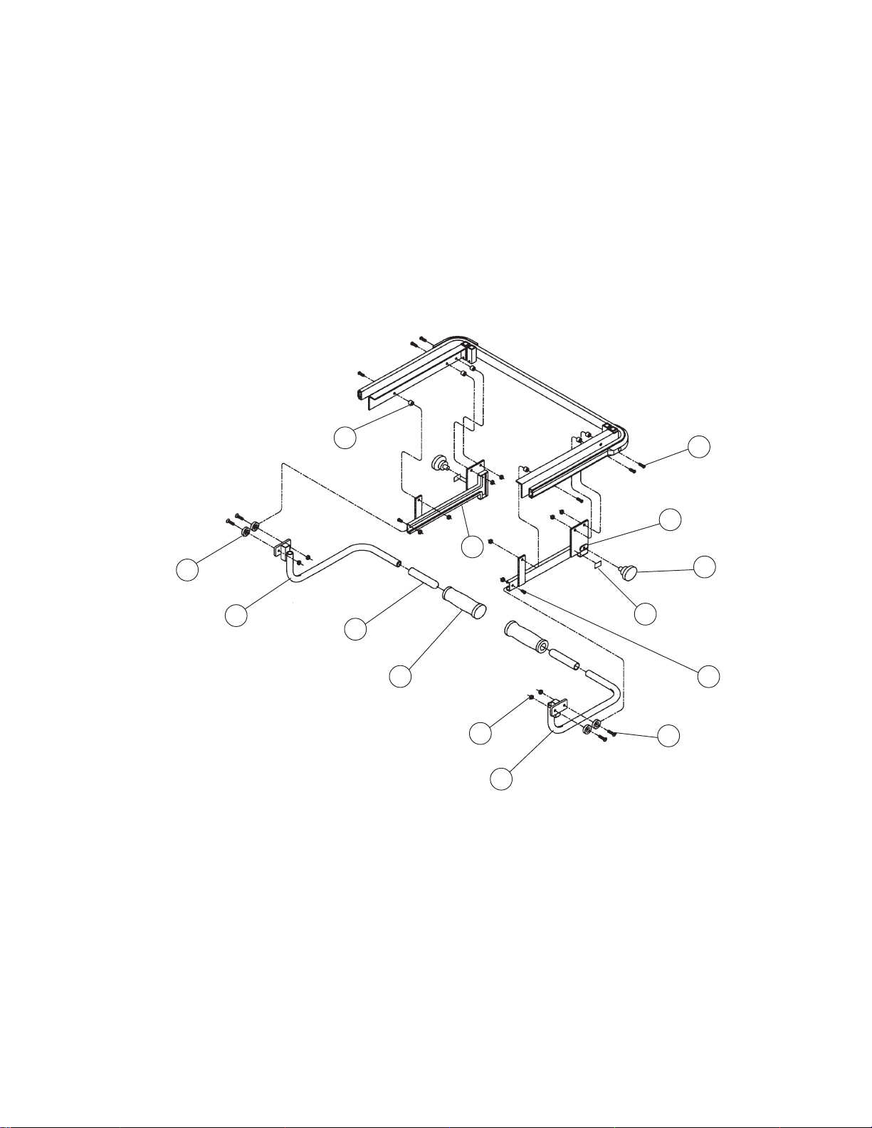
12
3
9
10
4
13
1
5
11
NOTE:
1. Apply petroleum lubricant to the inside of the channels.
2. Apply laquer to the inside of Items 5 & 11.
Figure 7-25. HMC Push Bar Assembly (Before 6/1/99)
14
7
8
2
6
7-52
069389 Operator Manual Recommended Replacement Parts
Page 78
FIG. &
ITEM
NO.
PART
NUMBER
S
V
DESCRIPTION
C
7-25- 068826 HMC PUSH BAR ASSEMBLY (BEFORE 6/1/99)....................... X
1 068828 WELDMENT, Push Handle, Left.................................................. 1
2 068827 WELDMENT, Push Handle, Right ............................................... 1
3 068831 CHANNEL, Push Handle, Left ..................................................... 1
4 068839 CHANNEL, Push Handle, Right................................................... 1
5 067144 GRIP, Push Bar Hand.................................................................. 2
6 066825 SCREW, Flat Head Cap, 1/4-20 x 1.0" Long ............................... 4
7 031327 SCREW, Button Head Socket, 1/4-20 x 1/2" Long ...................... 2
8 031055 NUT, Lock, 1/4 "........................................................................... 12
9 068663 GLIDE, Push Bar ......................................................................... 4
10 062038 SCREW, Button Head Socket, 1/4-20 x 3/4" long ....................... 6
11 068936 GRIP, Push Handle Comfort........................................................ 2
12 066237 SPACER ...................................................................................... 6
13 068879 LABEL, Lock ................................................................................ 2
14 068878 KNOB, Thread, 1/4-20 x 1.0" Long .............................................. 2
UNITS PER
ASSEMBLY
7-53
Recommended Replacement Parts Operator Manual 069389
Page 79
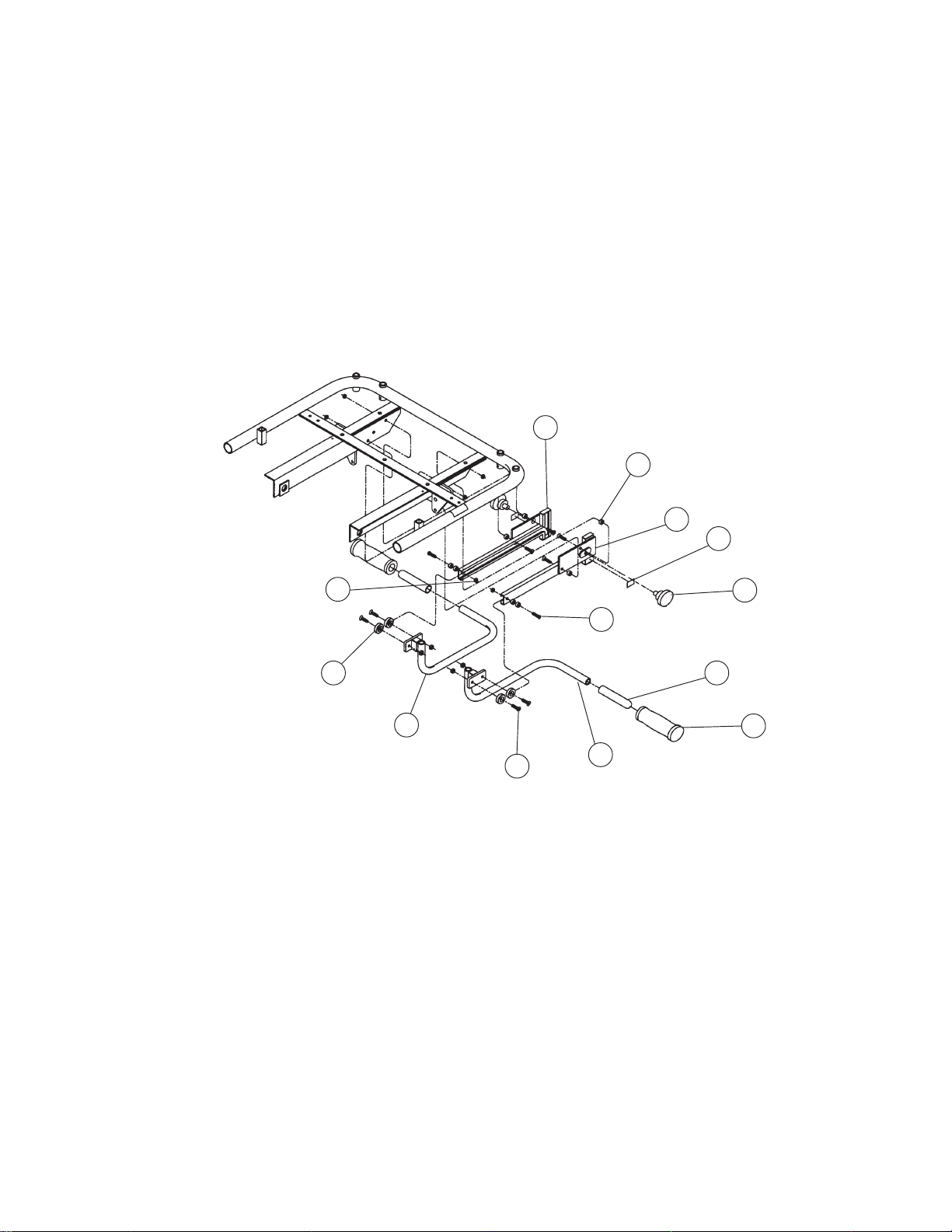
3
6
4
12
8
9
1
NOTE:
1. Apply petroleum lubricant to the inside of the channels.
2. Apply laquer to the inside of Items 5 & 11.
10
13
7
5
11
2
Figure 7-26. DPA Push Bar Assembly (Before 6/1/99)
7-54
069389 Operator Manual Recommended Replacement Parts
Page 80
FIG. &
ITEM
NO.
PART
NUMBER
S
V
DESCRIPTION
C
7-26- 068699 DPA PUSH BAR ASSEMBLY (BEFORE 6/1/99) ....................... X
1 068657 WELDMENT, Push Bar Handle, Left ........................................... 1
2 068661 WELDMENT, Push Bar Handle, Right......................................... 1
3 068648 WELDMENT, Push Bar Channel, Left ......................................... 1
4 068647 WELDMENT, Push Bar Channel, Right....................................... 1
5 067144 GRIP, Push Bar Hand.................................................................. 2
6 066649 BUSHING, Link ............................................................................ 8
7 031327 SCREW, Button Head Socket, 1/4-20 x 1.0" Long ...................... 2
8 031055 NUT, Lock, 1/4-20........................................................................ 12
9 068663 GLIDE, Push Bar ......................................................................... 4
10 066925 SCREW, Flat Head Cap, 1/4-20 x 1.0" Long ............................... 8
11 068936 GRIP, Push Handle Comfort........................................................ 2
12 068879 LABEL, Lock ................................................................................ 2
13 068878 KNOB, Thread, 1/4-20 x 1.0" ....................................................... 2
UNITS PER
ASSEMBLY
7-55
Recommended Replacement Parts Operator Manual 069389
Page 81
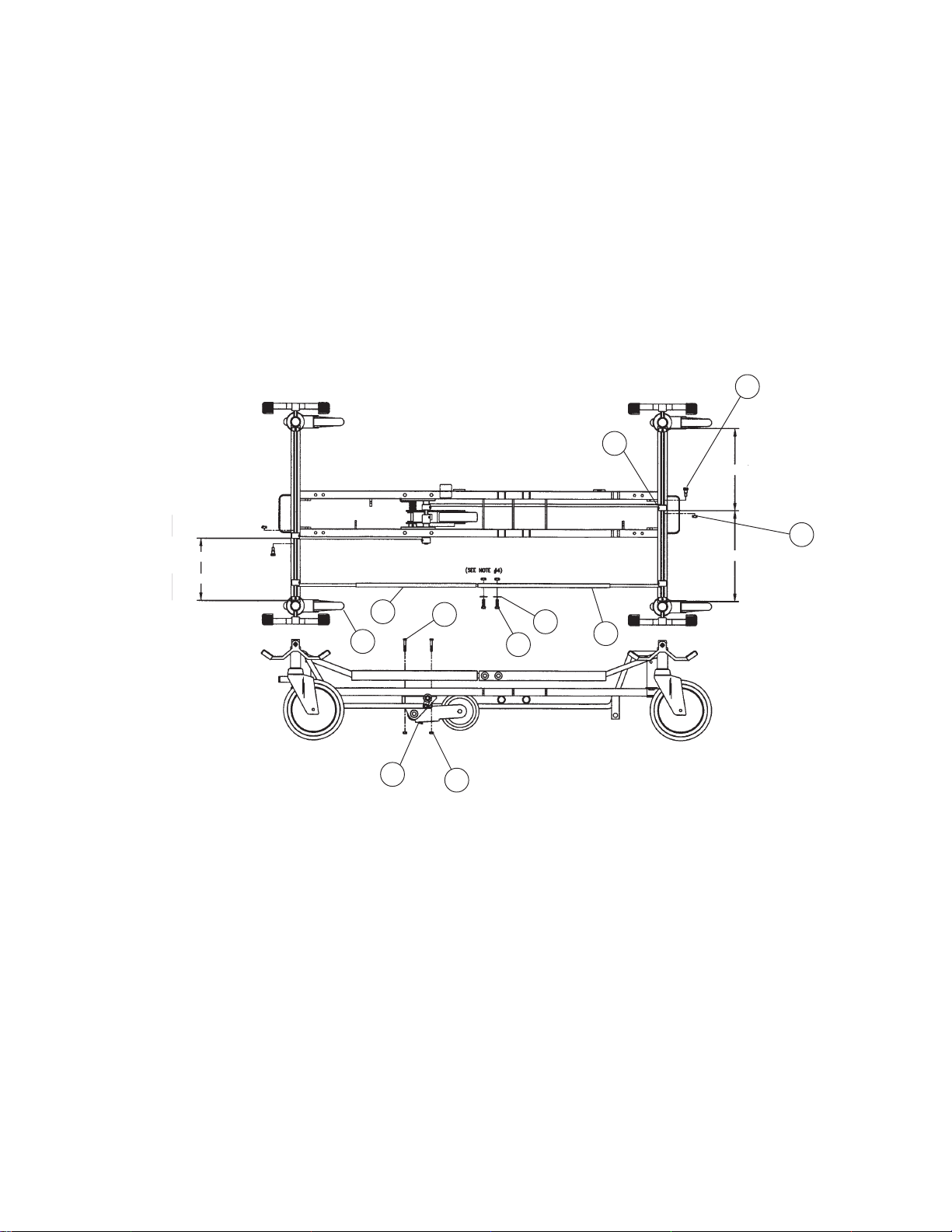
8.19 Hydraulic
8.88 Electric
4
6
8.88 Electric
5
12.00 Hydraulic
11
7
1
3
2
10
9
8
Figure 7-27. Fifth Wheel Assembly (After 9/1/99)
7-56
069389 Operator Manual Recommended Replacement Parts
Page 82
FIG. &
ITEM
NO.
7-27- 075798 00 FIFTH WHEEL ASSEMBLY – HORIZON ELECTRIC
1 075796 ASSEMBLY, Sub ......................................................................... – 2
2 031055 NUT, Lock, 1/4-20........................................................................ 4 4
3 031006 SCREW, Hex Head Cap, 1/4-20 x 1 1/4" Long ........................... 4 4
4 065807 BOLT, Shoulder, 3/8" x 3/8"......................................................... 2 2
5 031057 NUT, Lock, 5/16".......................................................................... 4 4
6 062684 CAM ............................................................................................. 2 2
7 075788 ROD, Brake, Foot End ................................................................. 1 1
8 075786 ROD, Brake, Head End................................................................ 1 1
9 031012 SCREW, Hex Head Cap, 5/16-18 x 1.00" Long .......................... 2 2
10 031080 WASHER, Flat, 5/16" ................................................................... 2 2
11 062672 CASTER, Tente, Brake................................................................ 1 1
12 065799 ASSEMBLY, Sub-, Electric .......................................................... 1 –
PART
NUMBER
075797 00 FIFTH WHEEL ASSEMBLY – HORIZON HYDRAULIC
S
V
C
(AFTER 9/1/99)........................................................................... X
(SHOWN) (AFTER 9/1/99) ......................................................... X
DESCRIPTION
NOTE: The hydraulic version of the fifth wheel
shown, use Item 12 in place of Item 1 and locate
cams as shown in drawing.
UNITS PER
ASSEMBLY
7-57
Recommended Replacement Parts Operator Manual 069389
Page 83
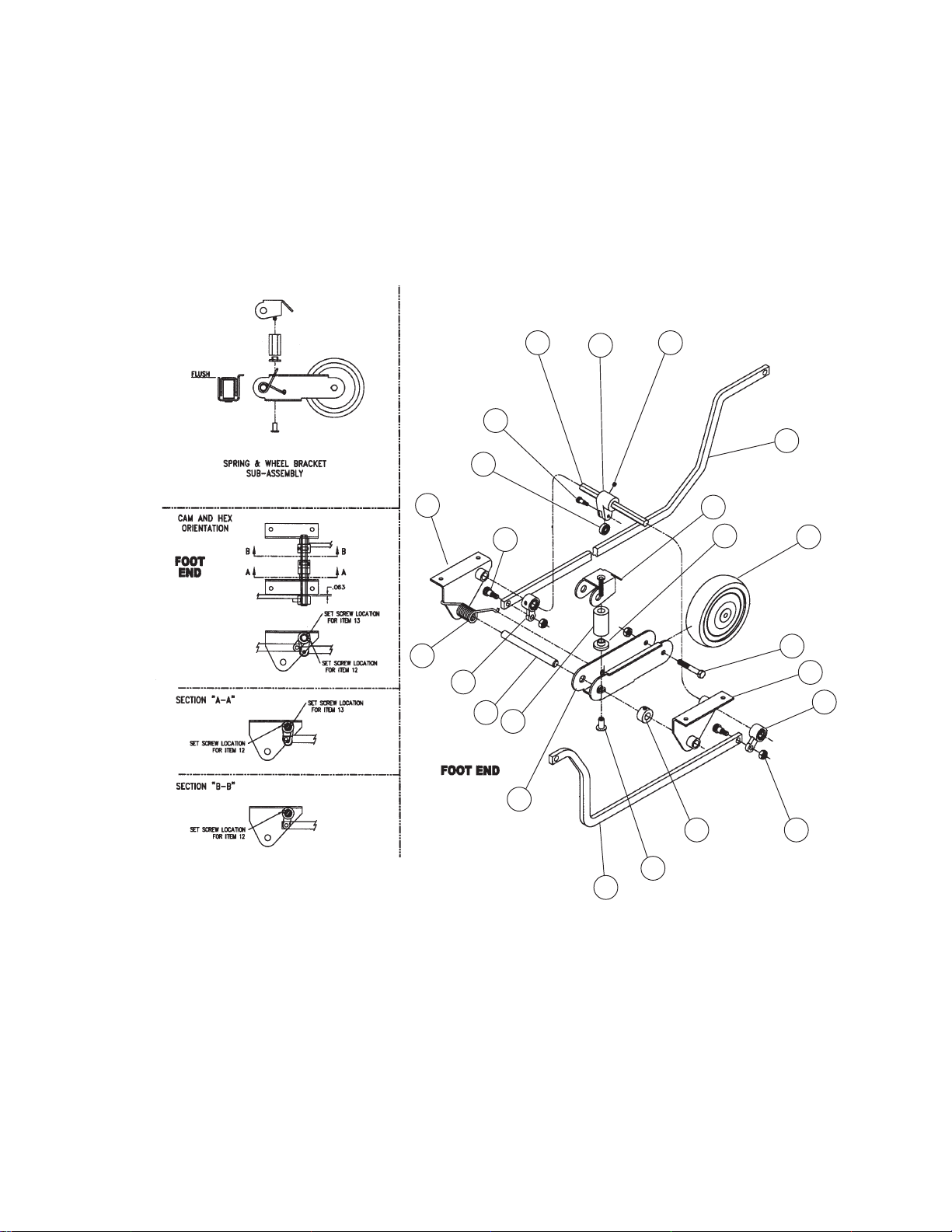
16
15
11
13
14
17
1
22
2
12
5
7
9
10
18
6
8
20
3 21
19
4
12
Figure 7-28. Fifth Wheel Assembly (After 9/1/99)
7-58
069389 Operator Manual Recommended Replacement Parts
Page 84
FIG. &
ITEM
NO.
PART
NUMBER
S
V
DESCRIPTION
C
7-28- 075799 00 FIFTH WHEEL SUB-ASSEMBLY– HORIZON ELECTRIC
(AFTER 9/1/99)........................................................................... X
075796 00 FIFTH WHEEL SUB-ASSEMBLY – HORIZON HYDRAULIC
(SHOWN) (AFTER 9/1/99) ......................................................... X
1 075775 WELDMENT, Mounting Bracket, Left Hand................................. 1 1
2 075771 SPRING, Torsion ......................................................................... 1 1
3 011422 COLLAR....................................................................................... 1 1
4 075776 WELDMENT, Mounting Bracket-Right Hand ............................... 1 1
5 075780 ROD, Pivot ................................................................................... – 1
6 075778 WELDMENT, Upper Bracket ....................................................... 1 1
7 075793 SPRING, Urethane ...................................................................... 1 1
8 075779 SPRING, Retainer........................................................................ 1 1
9 075772 BRACKET, Wheel ........................................................................ 1 1
10 068154 NUT, Spoke ................................................................................. 1 1
11 075781 ROD, Hex..................................................................................... 1 1
12 062684 CAM ............................................................................................. 2 2
13 075782 CAM, Auto Track.......................................................................... 1 1
14 067861 SCREW, Socket Set, 1/4-20 x 1/4" Long..................................... 1 1
15 075794 BOLT, Shoulder 1/4 x 3/8 ............................................................ 1 1
16 075792 BEARING..................................................................................... 1 1
17 075783 LINK, Long ................................................................................... 1 1
18 075784 LINK, Short .................................................................................. – 1
19 075785 WHEEL, 5th ................................................................................. 1 1
20 031334 SCREW, Hex Head Cap, 5/16-18 x 2" Long ............................... 1 1
21 031057 NUT, Lock, 5/16-18...................................................................... 3 3
22 065807 BOLT, Shoulder 3/8" x 3/8".......................................................... 2 2
23 076108 ROD, Pivot 6.5 ............................................................................. 1 –
24 076107 LINK, Short, Electric..................................................................... 1 –
UNITS PER
ASSEMBLY
7-59
Recommended Replacement Parts Operator Manual 069389
Page 85
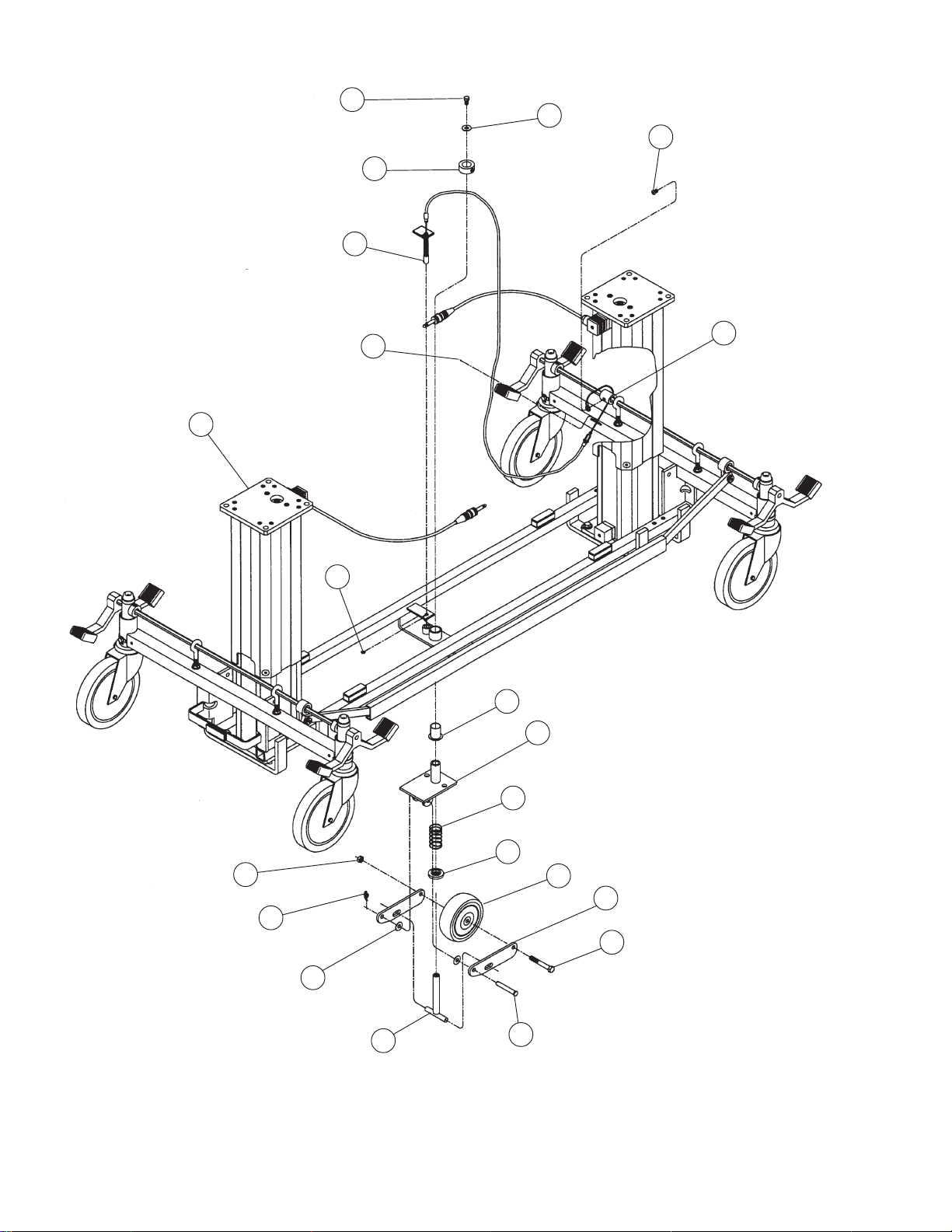
13
14
19
17
18
16
1
16
2
3
20
12
11
15
8
10
9
5
4
6
7
Figure 7-29. Fifth Wheel Assembly (Before 9/1/99)
7-60
069389 Operator Manual Recommended Replacement Parts
Page 86
FIG. &
ITEM
NO.
PART
NUMBER
S
V
DESCRIPTION
C
7-29- 068516 FIFTH WHEEL ASSEMBLY (BEFORE 9/1/99) .......................... X
1 ASSEMBLY, 4E2 Base ................................................................ 1
2 051308 NYLINER, Flange, 3/4" x 1-1/8"................................................... 1
3 068360 ASSEMBLY, Swivel Bracket ........................................................ 1
4 068429 PLATE, 5th Wheel Hinge ............................................................. 2
5 068415 WHEEL, 4th ................................................................................. 1
6 068543 SCREW, Hex Head Cap, 5/16-18 x 2-1/4" Long ......................... 1
7 068419 PIN, Clevis, 5/16" x 2.0"............................................................... 1
8 068417 CLIP, Rue, 5/16" .......................................................................... 1
9 068540 ASSEMBLY, Spring Stop............................................................. 1
10 065688 WASHER, Nylon, 5/1".................................................................. 2
11 068416 SPACER ...................................................................................... 1
12 068173 SPRING, 5th Wheel ..................................................................... 1
13 031004 SCREW, Hex Head Cap, 1/4-20 x 1/2" Long .............................. 1
14 031076 WASHER, 1/4" ............................................................................. 1
15 031057 NUT, Lock, 5/16-18...................................................................... 1
16 062640 RING, Retaining ........................................................................... 2
17 068464 COLLAR, 3/4" .............................................................................. 1
18 068430 ASSEMBLY, 5th Wheel Cable ..................................................... 1
19 068544 SCREW, Button Head Socket, 1/4-20 x 3/8" Long ...................... 1
20 068373 TUBE, Cam .................................................................................. 1
UNITS PER
ASSEMBLY
7-61
Recommended Replacement Parts Operator Manual 069389
 Loading...