

Page 1
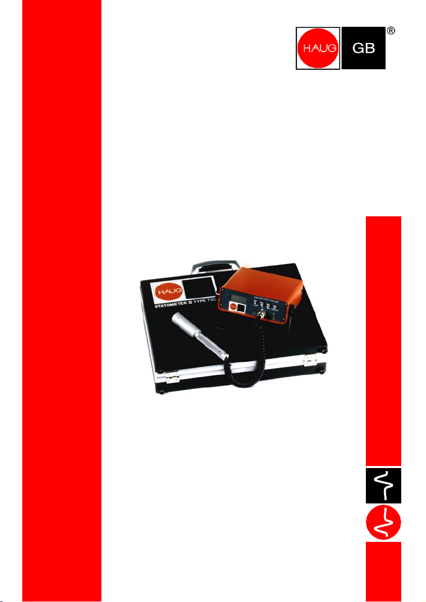
Statometer II
Operating instructions
Test Line
Page 2

Page 3
Types
: Statometer II with analog display 12.7215.000
Statometer II with digital display 12.7209.000
Keep in a safe place for future reference!
Contents
1. Notes on operating instructions 6. Troubleshooting
2. Safety 7. Maintenance and repairs
3. Design, control elements 8. Technical data
4. Preparing the initial start-up
5. Application
Incoming inspection:
1. Check the contents of the package for completeness.
2. Perform a visual inspection to determine any damage to the unit due to transportation.
3. In case of missing parts or other defects, complain to the forwarder without delay.
4. Inform a representative of the company HAUG GmbH & Co. KG in order to ensure that the
unit is repaired or replaced.
1 Notes on operating instructions
In these operating instructions, the Statometer II is also referred to as "the unit".
1.1 Pictorial markings used
In these operating instructions
Attention!
Important i
Warning!
nstructions!
Page 3
Page 4

2 Safety
The unit has been constructed and tested in accordance with the safety regulations for measuring
and control equipment and has left the plant in perfectly safe condition.
In order to maintain this status and ensure safe operation, observe the instructions and warnings
contained in these operating instructions.
2.1 Intended use
The Statometer II is intended for the measurements of electric fields on flat surfaces. It provides
fast measurements of electric fields created, for example, through charges on surfaces of plastic,
paper, glass and other materials.
For reasons of safety, unauthorized conversions and modifications of the unit are not permitted.
The installation and operating conditions indicated in these Operating Instructions must be
adhered to.
2.2 Storage of the Statometer II
For storage, remove the rechargeable batteries from the battery compartment underneath. Check
the rechargeable batteries before putting the Statometer II into operation and recharge, if
necessary.
Do not open the unit!
Do not use ord
Only use NiMH cells!
Surfaces must be larger than the measuring head diameter (Ø 30 mm).
In case of co
falsified!
inary batteries!
nvex or concave surfaces, the measuring value will be
2.3 Danger sources
In cases where safe operation cannot be ensured, switch off the unit and secure it against being
switched on inadvertently.
Terminals may be energized.
2.4 Operator qualifications
The unit and its related components may be put into operation, used and maintained only by
persons who have read the operating instructions and follow the instructions, notes and safety
advice.
Page 4
Page 5
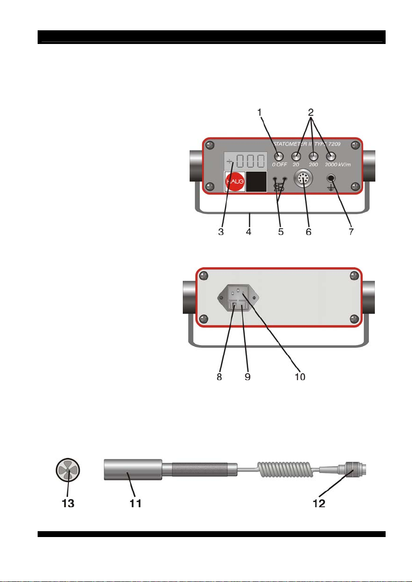
3 Design, control elements
Figure 1
1. Pushbutton switch (unit off)
2. Pushbut
3. Display (digital or analog)
4. Carrying handle / stand
5. Recorder output
6. Measuring head port
7. Ground connection
Figure 1
Figure 2
8. Set m
9. Fuse holder
10. Socket for non-heating apparatus
Figure 2
Figure 3
11. Measuring head
12. Measuring head connector
13. Impeller
Figu
ton switch (unit on and range selection)
ains voltage
re 3
Page 5
Page 6

4 Preparing the initial start-up
The unit and its related components may be put into operation, used and maintained only by
persons who have read the operating instructions and follow the instructions, notes and safety
advice.
4.1 Setting up, connecting
1. Before connecting, always check whether the unit is suitable for use with the local mains
voltage. The unit is designed for operation with rechargeable battery, 230 V and 115 V. The
mains voltage is indicated by the number on the fuse holder (Section 3, item 8). To change
the mains voltage, refer to Section 4.2 Mains voltage. The unit will be destroyed if used with
wrong mains voltage.
2. Set up unit at the desired location. Do not place the unit on a surface generating or radiating
heat. Avoid locations exposed to direct sunlight.
3. Ensure that the unit is switched off (off-switch depressed, refer to Section 3, item 1).
4. Ground the unit via the ground connector (Section 3, Pos. 7) using the enclosed grounding
cable.
5. Plug the measuring head connector into the measuring head port (Section 3, item 6) and
screw tight.
6. If required, a recording instrument can be connected to the recorder output (Section 3, item
5).
7. Connect the Statometer II to the mains unless working in battery mode.
8. Put unit into operation.
In case of battery operation, always ensure grounding!
The display will indicate low battery voltage.
Analog = Both polarity LEDs light up
Digital = LO BAT is displayed
Protect measuring head from contamination (e.g. water, oil).
Page 6
Page 7

4.2 Setting the mains voltage
On delivery from the factory, the unit is set to a voltage of 230 V.
Check the set mains voltage by reading the number on the fuse holder (refer to Section 3, Para.
2).
Changing the voltage range:
1. Switch off the unit and isolate from the mains.
2. Pull the cable out of the socket for non-heating apparatus at the rear of the unit.
3. Detach the fuse holder in the socket (spring lock) and pull out.
4. Replace the fuse (230 V = 100 mA slow; 115 V = 200 mA slow).
5. Pull out the fuse with the fuse cage from the fuse holder and reattach after turning by 180° .
The new voltage range is now visible on the fuse holder.
6. Reinsert the fuse holder into the socket. Press the fuse holder until the spring lock snaps into
place on both sides.
When setting the mains voltage range, ensure that the correct fuse is
used (refer to Section 7.2).
4.3 Inserting the NiMH batteries
The NiMH batteries are charged when the unit is connected to the mains.
1. Open the cover underneath the unit.
2. Insert the batteries observing the polarity marking.
3. Close the cover.
Observe the polarity when inserting the batteries.
ly use NiMH cells!
On
Page 7
Page 8
5 Application
Preconditions:
The Statometer II and its components must have been connected correctly.
The position of the Statometer II does not affect its functioning.
5.1 Determination of the field intensity
1. Check whether the chassis ground connection has been made. No reliable measurements
can be made unless the unit is grounded via the ground terminal (Section 3, item 7).
2. Pull the protective cap from the measuring head and check for contamination. Clean, if
required (refer to Section 7.1).
3. Keep the measuring head away from electric fields to perform the zero calibration. Press the
range selector button. The impeller in the measuring head now turns, and the unit will
perform an automatic zero calibration.
4. Move the measuring head vertically towards to the measuring surface. The measuring
distance amounts to 30 mm.
5. Read the amount and polarity of the field intensity measured from the display.
6. In case of a capacitor field, the value displayed is not corrected. In case of measurements on
flat surfaces, the displayed value will be corrected by a factor of 1.5.
Example: Measuring value 12 kV/m
Capacitor field 12 kV/m x 1 = 12 kV/m
Surface area 12 kV/m x 1.5 = 19.2 kV/m
Surfaces must be larger than the measuring head diameter (Ø 30 mm).
In case of co
falsified!
In case of very high field intensities and insufficient measuring distance,
a sparkover to the measuring head may occur.
nvex or concave surfaces, the measuring value will be
Page 8
Page 9
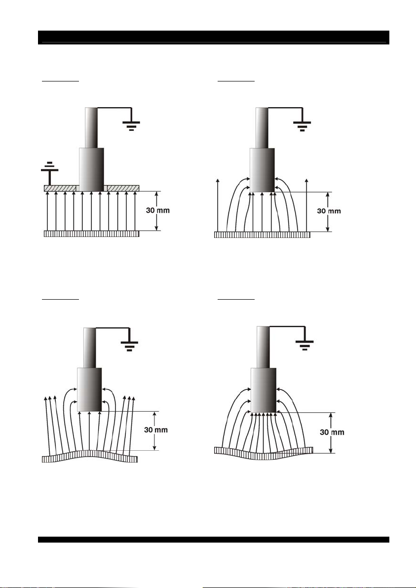
Measuring exa
Example 1
Measuring head Measuring head
Capacitor field
display x 1.5 (calibrated in a capacitor field with a plate size
Example 3
Measuring head Measuring head
Convex surface
indicated measuring value too small indicated measuring value too high
mples:
Example 2
Flat surface
300 mm x 300 mm)
Example 4
Concave surface
Page 9
Page 10

5.2 Determination of potential
The potential (voltage level) of the measured surface area can be determined from the field
intensity measuring value.
The following relationship applies:
Field intensity (in kV/m) x measuring distance (in m) = Potential (in kV)
The measuring distance for the Statometer II is: 30 mm = 0,03 m
Example: Field intensity determined = 12 kV/m
Potential (in kV) = 12 kV/m x 0,03 m = 0.36 kV = 360 V
5.3 Determination of charge density
The surface charge density is proportional to the normal component of the electric field. The
connection is made using the absolute permittivity
The charge density therefore results from the equation
Charge density = field intensity x absolute permittivity
For the
above example:
= 12 kV/m x 8,86 x 10
-12
As/Vm = 106,32 x 10⁻⁹ As/m2
= 8,86 x 10
0
-12
As/Vm.
6 Remedy of defects
In case of malfunction in connection with the Statometer II, first check for correct installation and
fusing (for replacement, refer to Section 7.2). If this does not solve the problem, please return the
Statometer II and the measuring head to HAUG for a check-up.
Page 10
Page 11
7 Maintenance and repairs
This unit does not include any parts which can be repaired by the operator.
HAUG only is authorized to repair or calibrate the unit.
Should the unit prove defective or if a defect is suspected, switch off unit immediately and secure
against subsequent reuse.
7.1 Cleaning
The measuring head, and in particular the impeller (refer to Section 3, Fig. 3), must be free of
contamination with water, oil or dust. Clean any contamination from the impeller in the measuring
head using a dry, soft brush. Any deformation or damage to the impeller will result in false
measuring results.
7.2 Changing the fuse
1. Switch off the unit and isolate from the mains.
2. Pull the cable out of the socket for non-heating apparatus at the rear of the unit.
3. Detach the fuse holder in the socket (spring lock) and pull out.
4. Replace the fuse.
5. Reattach the fuse holder.
Use the following fuses only:
Unit type Mains voltage range Fuse
Statometer II 115 V 200 mA slow; 5 x 20 mm
Statometer II 230 V 100 mA slow; 5 x 20 mm
Only use fuses of the type indicated.
7.3 Accessories
Measuring head with 60 cm coiled cable
Laboratory cable with 4 mm plug
4 NiMH batteries, 1.2 V
Swan-neck
Clamp for measuring head
Magnetic holder
Measuring record block
Portable measuring case with insert and writing pad
Page 11
Page 12

8 Technical data
8.1 Characteristics and specification
Reference temperature 23 °C
Display:
Digital (12.7209.000) 3
Analog (12.7215.000) Moving-coil instrument with mirrored scale,
Measuring ranges:
Range 1 -20 kV/m to +20 kV/m
Range 2 -200 kV/m to +200 kV/m
Range 3 -2000 kV/m to +2000 kV/m
Measuring distance 30 mm
Analog output:
Output voltage -2 V to +2 V ( Imax = 0.2 mA )
Measuring accuracy:
Digital ±10 %
Analog ±15 %
Over-range:
Digital Display indicates I.
Analog Pointer exceeds the upper scale value
Battery check:
Digital Display indicates LO BAT
Analog Both polarity indicating diodes light up
1
/2 -digit liquid-crystal display
polarity display by means of light-emitting diodes
3 mm
8.2 Supply voltage
Mains:
Voltages 115 V / 230 V (+6 % / -10 %)
Frequency range 50 – 60 Hz
Frequency tolerance range 47,5 – 66 Hz
Power input 10 VA
Rechargeable battery operation:
Number of cells 4 NiMH round cells (AA)
Cell voltage 1,2 V
Battery operation time approx. 5 h at 800 mAh cell capacity
Page 12
Page 13

8.3 Ambient conditions
Ambient temperature:
Reference value + 23 °C ±1 °C
Rated application range 0 °C to +40 °C
Extreme range for storage and transport -20 °C to +60 °C
Humidity:
Reference range 45 % to 75 % RF
Limit range of operation 10 % to 85 % RF
Rated application range 20 % to 80 % RF
Extreme range for storage and transport 0 % to 85 % RF
Air pressure:
Reference value 1013 mbar
Rated application range 800 mbar to 1060 mbar
Flow rate of ambient air:
Reference range 0 m/s to 0.2 m/s
Vibrations:
Extreme range for storage and transport max. 1.5 g (10 to 55 Hz), 1 h
Shock: max. 15 g in each direction
8.4 Housing
Protection type IP 20
Mains connection Mains cable via socket for non-
Dimensions:
Height approx. 66 mm
Width approx. 211 mm
Depth approx. 180 mm
Weight approx. 1 kg
heating apparatus
Page 13
Page 14

Page 15

Page 16

made by
Statom2 v04gb.doc
D – 0225 – GB
V04
2012-01-25
 Loading...