

Page 1
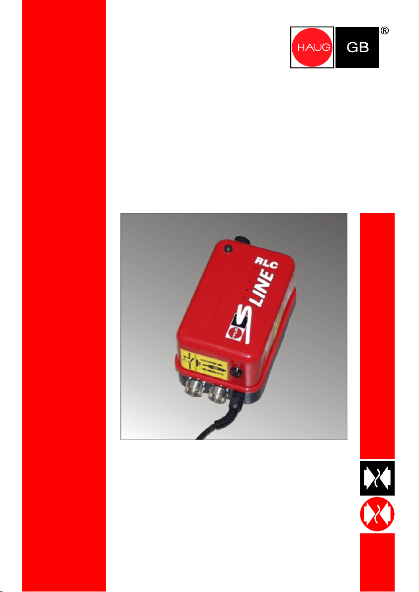
EN SL / EN SL LC / EN SL RLC
Keep for future use!
Power Pack
Static Line
Operating instructions
Page 2

Page 3

Table of contents
1
Operator instructions........................................................................ 5
2 Safety ................................................................................................. 6
3 Intended use...................................................................................... 8
4 Description of unit............................................................................. 9
5 Installation ....................................................................................... 10
6 Application....................................................................................... 14
7 Troubleshooting .............................................................................. 15
7.1 Replacing fuse ............................................................................................ 16
7.2 Flow chart.................................................................................................... 17
8 Accessories..................................................................................... 18
9 Technical data ................................................................................. 20
9.1 Characteristics and specification................................................................ 20
9.2 Supply voltage ............................................................................................ 21
9.3 Ambient conditions ..................................................................................... 22
9.4 Connected lengths...................................................................................... 23
9.5 Housing ....................................................................................................... 24
10 Decommissioning ........................................................................... 25
11 Disposal ........................................................................................... 26
3
Page 4

Types and order numbers
EN SL without thermal cutout:
01.7780.200, 01.7780.208, 01.7780.220, 01.7781.200, 01.7781.208, 01.7781.220
EN SL with thermal cutout:
01.7830.000, 01.7831.000
EN SL LC with thermal cutout and signalling lamp:
01.7833.000, 01.7833.050, 01.7834.000, 01.7834.050
EN SL RLC with thermal cutout, signalling lamp and signalling socket:
01.7835.100, 01.7835.150, 01.7836.100, 01.7836.150
4
Page 5
1 Operator
instructions
These operator instructions must be
read completely before inst
commissioning of the power pack.
They form a part of the power pack
and must be retained for later use or
subsequent owners.
Safety instructions must be observed
and followed at all times.
The power pack is operationally safe,
provided that it is operated in
accordance with its intended use.
The power pack is maintenance-free.
allation and
1 Operator instructions
The following signal words are
used:
WARNING!
If ignored
severe personal injury.
or death may result.
ATTENTION!
If ignored
light property damage with
damage to the power pack may
result.
NOTE: Important notes and additional
information.
5
Page 6

2 Safety
2 Safety
All activities must be performed only
by persons authorized by the owner.
Such persons must
be qualified in electrical
engineering.
have read and understood the
operator instructions.
Switch off the power supply before
commencing work on the power pack,
and secure against inadvertent
switching on.
With the exception of the fuse, the
power pack does not include any parts
which can be repaired by the operator.
For reasons of safety, unauthorized
conversions and modifications of the
power pack are not permitted.
Any damage to the power pack may
result in the risk of electric shocks. In
the event of any visible damage or
suspected electrical defects, take the
power pack out of operation
immediately and secure against reuse.
WARNING!
Risk of electric shock.
High electric voltage in power pack.
Risk of electric shock when touching
live parts within power pack.
Do not open the power pack.
6
Page 7

ATTENTION!
Risk of short circuit.
Spark-overs and leakage paths at the
high-voltage terminals can occur as a
result of moisture and wetness.
Short circuits within the power pack
are the likely consequence.
Protect the power pack from
wetness and moisture.
Close unused high-voltage
terminals with the red blind plugs.
Risk of spark-over.
When the power pack is switched on,
contact or separation spark-overs may
occur when the ionizing unit is
plugged in or unplugged at the highvoltage socket.
This may result in damage to the
power pack or defects.
Only plug in/unplug the ionizing
unit at the high-voltage socket
when the power pack is switched
off.
2 Safety
7
Page 8
3 Intended use
3 Intended use
The power pack is intended
exclusively for the supply of alternating
high voltage to HAUG ionizing units
with X - 2000 connector.
Only HAUG ionizing units with X - 2000
connectors must be connected with
the power pack and operated.
The warranty only covers units and
accessories of HAUG
GmbH & Co. KG.
The installation and operating
conditions indicated in these
Operating Instructions must be
adhered to.
WARNING!
Risk of explosion!
Ignitable sparks may form at the
power pack.
Do not install or use the power
pack in areas subject to
explosion hazards.
8
Page 9
4 Description of unit
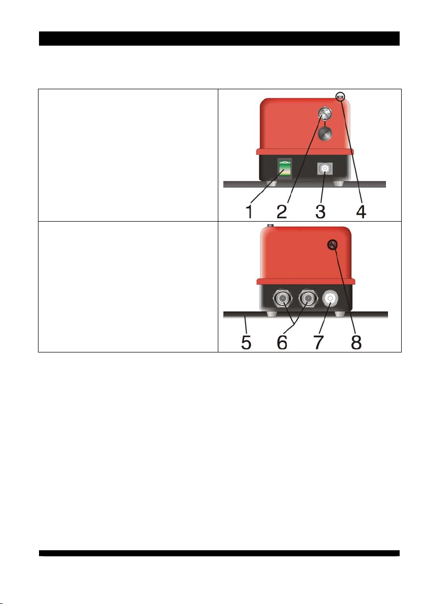
1) Mains switch
Green light in switch
illuminates when power pack
is on.
2) Signalling socket (RLC types only)
3) Ground connection (terminal)
4) Signalling lamp (LC and RLC
types only)
5) Bracket
6) High-voltage terminals
7) Mains supply
8) Fuse holder with fuse (for
replacement, refer to page 16,
Chapter 7.
1).
4 Description of unit
9
Page 10
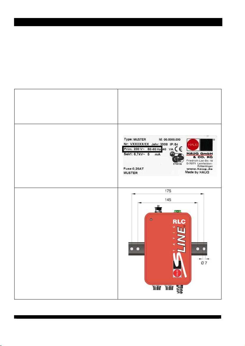
5 Installation
5 Installation
Do not place the power pack on a
surface generating or radiating heat.
Avoid installation location exposed to
direct sunlight.
1. Check the model plate of the power
pack against the ordering data.
In the event of damage to the power
pack, contact HAUG
GmbH & Co. KG.
2. Before connecting, check to ensure
that the power pack is suitable for
the local mains voltage.
The voltage is indicated on the
model plate attached at the side
of the power pack.
An incorrect mains voltage may
result in damage to the power
pack.
3. Use the enclosed bracket to install
the power pack at the desired
location.
The operation of the power pack
is not affected by the position in
which it is installed.
We recommend installing the
power pack with the high-voltage
terminals pointing downwards
(to protect them from moisture,
oil and dirt).
10
Page 11
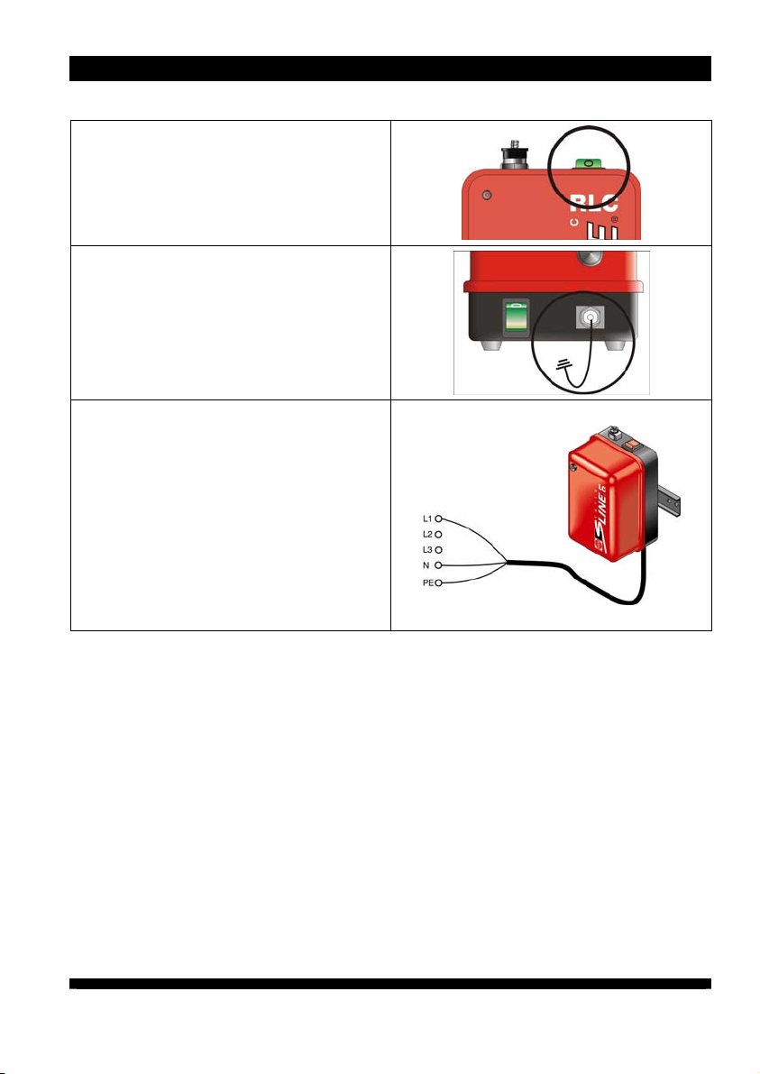
4. Ensure th
switched off.
5. Connect the ground socket of the
power pack with the machine
ground connection.
6. Connect the power pack to the
mains. Connect the PE conductor
(green-yellow) with the protective
earth of the mains.
at the power pack is
Connecting the PE conductor via
parts of a machine body is
insufficient.
L1 = brown conductor
N = blue conductor
PE = green/yellow conductor
5 Installation
11
Page 12
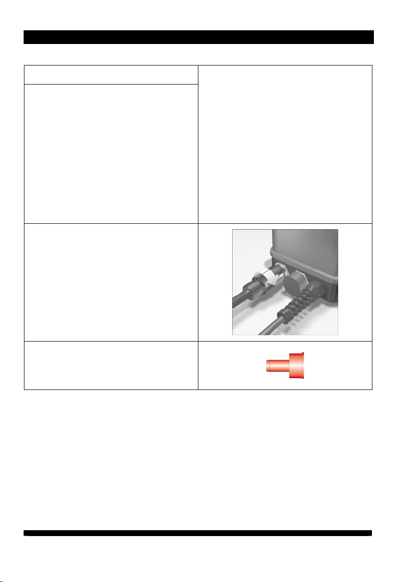
5 Installation
ATTENTION!
Risk of overheating.
If the maximum permissible connected
length is exceeded, the power pack will
overheat during operation.
This may result in damage to power
packs not equipped with thermal cutout
and cause a fault.
The maximum permissible
connected length must not be
exceeded.
For connected lengths for the power
pack, refer to page 23.
7. Connect the ionizing unit to the
high-voltage terminal.
Plug the high-voltage connector
of the ionizing unit into the highvoltage socket of the power pack
and push at the high-voltage
cable until the stop is reached.
Screw the screw cap onto the
high-voltage socket and tighten
by hand.
NOTE: Protect unused high-voltage
terminals against the ingress of
environmental substances using the red
blind plugs.
12
Page 13
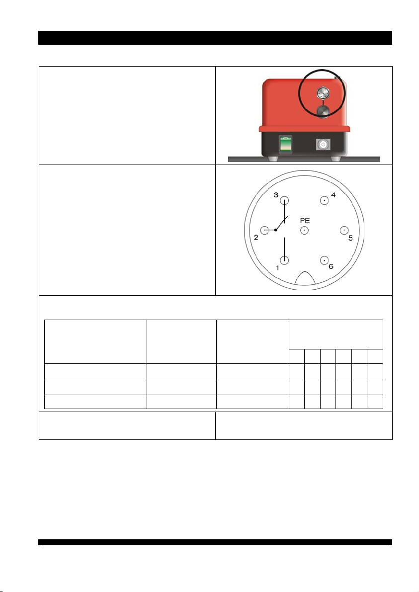
RLC types onl
8. If required – if an error message
needs to be evaluated, connect the
signalling line to the signalling
socket.
Configuration of the signalling socket.
Pin 1: Switching contact
Pin 2: Joint connection relay
Pin 3: NC contact
Pin 4: Not assigned
Pin 5: Not assigned
Pin 6: Not assigned
PE: Shield ground
Switching status table for signalling socket.
y
5 Installation
Mains voltage High-voltage
Normal operation yes yes x x
Mains failure no no x x
High voltage failure yes no x x
9. The power pack is ready for
operation.
Contacts closed
123456
13
Page 14

6 Application
6 Application
Preconditions:
The power pack and the ionizing unit
must be connected and installed as
specified in the operator instructions.
1. Switch on the power pack using
the mains switch.
The mains switch will
illuminate to confirm.
2. The power pack is in operating
mode.
3. In the event of an operating fault,
the signalling lamp will flash.
Only applies to LC and RLC
types.
In the case of RLC type, a
signal will be output at the
signalling socket.
To remedy the fault, carry out
the troubleshooting
procedure.
NOTE: Types with thermal cutout will
switch off when overheated. The
signalling lamp will flash. Determine
and remove the cause of overheating
by carrying out the troubleshooting
procedure.
14
Page 15
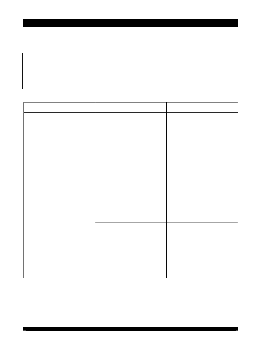
7 Troubleshooting
7 Troubleshooting
NOTE: If the error cannot be removed
in this way, return the power pack and
ionizing unit for checking to HAUG
GmbH & Co. KG (for address, see
reverse).
Error Cause Measure for elimination
No ionization
Mains failure Check mains fuse.
No high voltage
Only applies to types with
thermal cutout:
A short circuit will result in
the power pack
overheating. The installed
thermal cutout will switch
the power pack off.
Only applies to types with
thermal cutout:
Exceeding the permitted
connected length will
result in the power pack
overheating. The installed
thermal cutout will switch
the power pack off.
Check fuse in power pack.
Check connections in
power pack.
Check high-voltage output
using the Combicheck
(see accessories).
Replace faulty ionizing unit
and allow the power pack
to cool down for at least
15 min.
Check the connected
length and allow the
power pack to cool down
for at least 15 min. For
permissible connected
lengths, refer to page 23.
15
Page 16
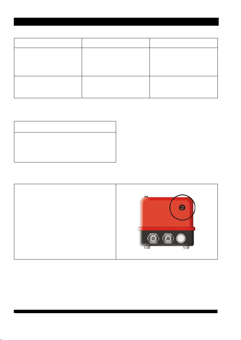
7 Troubleshooting
Error
No ionization The power pack is
Signalling lamp flashing
(EN SL LC and EN SL RLC
only)
Cause Measure for elimination
damaged.
The ionizing unit is faulty. Follow work sequence
7.1 Replacing fuse
Shut the power pack
down immediately and
secure against switching
on.
according to the flow chart
below.
ATTENTION!
Risk of faults!
An incorrect fuse in the power pack may
cause a fault.
Only use fuses of the type indicated.
The unit type and the rated voltage are
indicated on the nameplate.
1. Disconnect power pack from supply.
2. Determine and remove the cause for
the blown fuse.
3. Detach the fuse holder using a
screwdriver and lift out.
4. Replace fuse and reattach fuse
holder.
Use the following fuse only:
115 V = 0,50 A slow, 5 x 20 mm
230 V = 0,25 A slow, 5 x 20 mm
16
Page 17
y
(
)
(
)
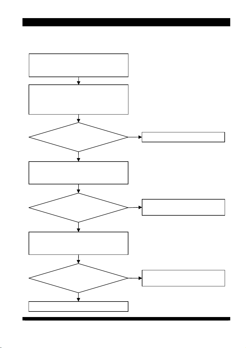
7.2 Flow chart
Indicator lamp flashes ( LC/RLC ) or
relay contact ( RLC ) switches to fault.
Switch off power pack and unplug
ionizing units.
Allow power pack to cool down for 15
minutes and then switch on.
7 Troubleshooting
Signalling lamp
flashing?
no
Switch off power pack and plug in
ionizing unit.
Switch on power pack.
Signalling lamp
flashing?
no
Switch off power pack and plug in
another ionizing unit.
Switch on power pack.
Signalling lamp
flashing?
no
yes
yes
Ionizing unit is faulty.
Short circuit
yes
Ionizing unit is faulty.
Short circuit
Power pack is fault
Ionizing system is ok
17
Page 18
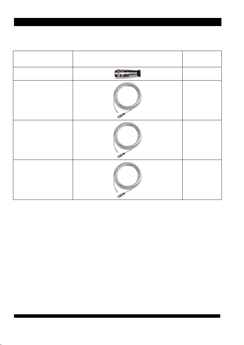
8 Accessories
8 Accessories
Article Illustrations
Signal plug
5 m shielded
signalling line K6 with
assembled plug
10 m shielded
signalling line K6 with
assembled plug
20 m shielded
signalling line K6 with
assembled plug
Order
number
X – 7807
06.8976.000
06.8976.001
06.8976.002
18
Page 19
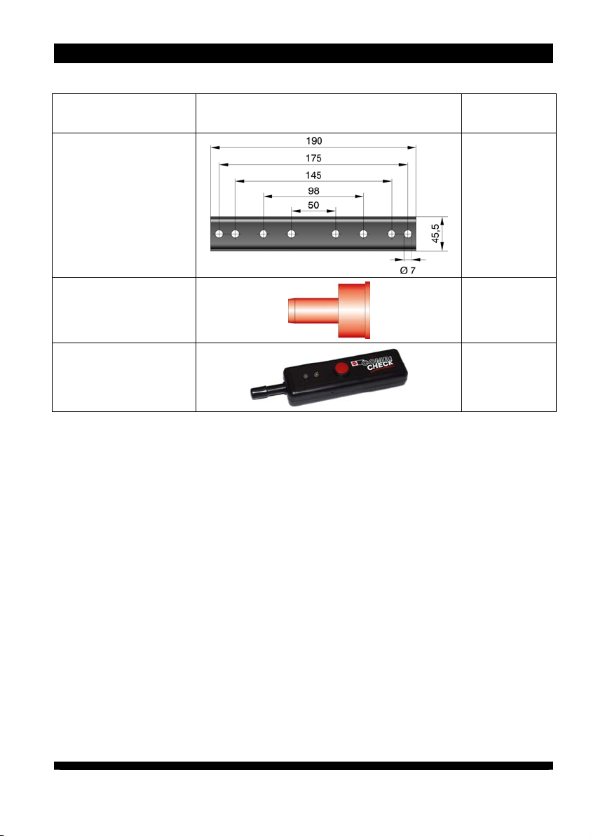
Illustrations
Article
8 Accessories
Order
number
Bracket for power
pack
Blind plug for HV
terminals
Combicheck
10.0023.000
X – 1080
12.7231.000
19
Page 20
9 Technical data
9 Te c h n i c a l d a t a
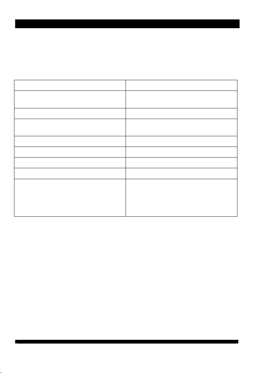
9.1 Characteristics and specification
Reference temperature 23 °C
High-voltage terminals 2 HAUG- High-voltage terminals
Connectable HAUG ionizing units
High-voltage U = approx. 7 - 8 kVAC
Signalling terminal EN SL RLC
Cannot be used in pulsed mode
Short-circuit current:
01.7780.220, 01.7781.220
01.7780.200, 01.7780.208, 01.7781.200,
01.7781.208, 01.7830.000, 01.7831.000,
01.7833.000, 01.7833.050, 01.7834.000,
01.7834.050, 01.7835.100, 01.7835.150,
01.7836.100, 01.7836.150
All HAUG ionizing units fitted with
X - 2000 connector
Contact load max. 24 VAC/35 VDC,
max. 50 mA
Ik 3 mA
Ik 5 mA
20
Page 21
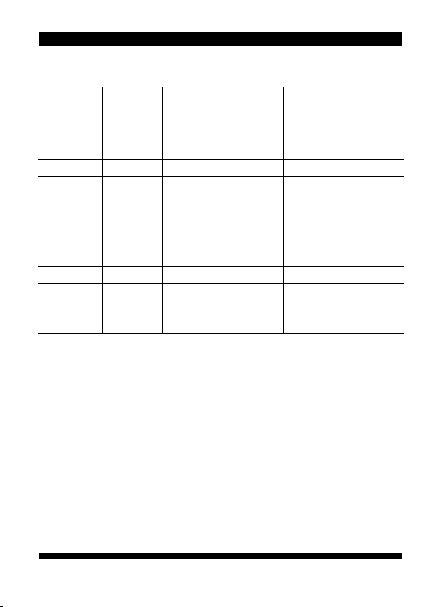
9.2 Supply voltage
9 Technical data
Unit type
Nominal
value
Operating
range
Frequency
range
01.7781.208,
01.7834.050,
100 VAC ±10 % 50 - 60 Hz P
01.7836.150
01.7781.220 115 VAC ±10 % 50 - 60 Hz P
01.7781.200,
01.7831.000,
01.7834.000,
115 VAC ±10 % 50 - 60 Hz P
01.7836.100
01.7780.208,
01.7833.050,
200 VAC ±10 % 50 - 60 Hz P
01.7835.150
01.7780.220 230 VAC ±10 % 50 - 60 Hz P
01.7780.200,
01.7830.000,
01.7833.000,
230 VAC ±10 % 50 - 60 Hz P
01.7835.100
Power input
= 40 VA
max
= 20 VA
max
= 40 VA
max
= 40 VA
max
= 20 VA
max
= 40 VA
max
21
Page 22
9 Technical data
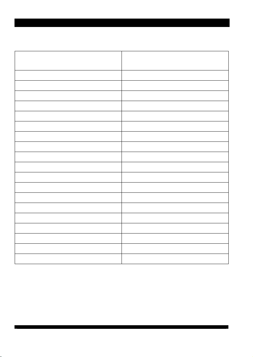
9.3 Ambient conditions
Do not use in areas with potentially
explosive atmospheres.
Only for inside use.
Temperature:
Rated application range +5 °C to +45 °C
Extreme range for storage and transport -15 °C to +60 °C
Humidity:
Rated application range 20 % to 65 % RF
Extreme range for storage and transport 0 % to 85 % RF
Air pressure:
Rated application range 800 mbar to 1060 mbar
Vibrations:
Extreme range for storage and transport max. 1,5 g (10 to 55 Hz), 1 h
Shock max. 15 g in each direction
Recommended service position: vertical, supply cable downwards
22
Page 23
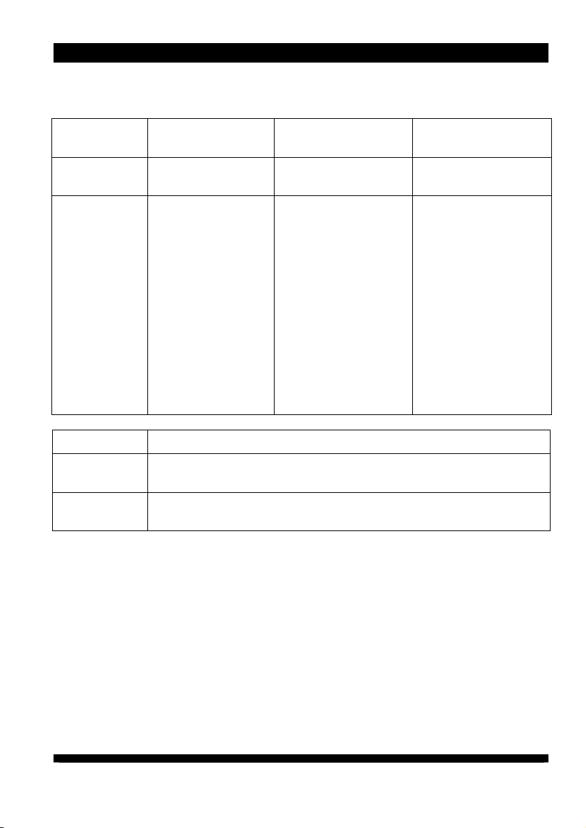
9.4 Connected lengths
9 Technical data
Power Pack
01.7780.220,
01.7781.220
01.7780.200,
01.7780.208,
01.7781.200,
01.7781.208,
01.7830.000,
01.7831.000,
01.7833.000,
01.7833.050,
01.7834.000,
01.7834.050,
01.7835.100,
01.7835.150,
01.7836.100,
01.7836.150
Ionizing bar
Type A
Type B
Ionizing bar Type A:
The maximum cable length (KL) is the permissible connected length (AL) minus the
maximum ionizing bar length (SL).
KL = AL – SL
Ionizing bar Type B:
The maximum cable length (KL) is the permissible connected length (AL) minus 3 x the
maximum ionizing bar length (SL).
KL = AL – (3*SL)
Permissible
connected length
5 m 4.7 m 1.4 m
10 m 6 m 3 m
EI RN, EI RNE, EI RA, EI RAE, EI RNOF, EI RAOF, EI HRN, EI HRA,
EI HRE, EI HRAE, EI PS, EI PRX, EI PRV, EI SL, EIW
EI VS, EI VSE, EI VSA, EI VSAE, EI VC, EI VCA, EI VCE, EI VCAE,
EI VSOF, EI VSAOF
Maximum ionizing
bar length Type A
Maximum ionizing
bar length Type B
23
Page 24
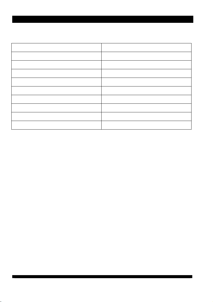
9 Technical data
9.5 Housing
Protection type IP 54
Protection class I
Mains supply approx. 2,6 m fixed on unit
Dimensions:
Height approx. 170 mm
Width approx. 110 mm
Depth approx. 100 mm
Weight: approx. 3.5 kg
24
Page 25

10 Decommissioning
1. Switch off the machine and secure
against unintended switching on.
2. Switch off power pack and secure
against inadvertent operation.
3. Disconnect the ionizing unit from
the power pack.
4. Disconnect the power pack from
the mains and remove.
10 Decommissioning
25
Page 26

11 Disposal
11 Disposal
Observe and maintain national and
regional waste disposal regulations for
the disposal of the power pack.
26
 Loading...